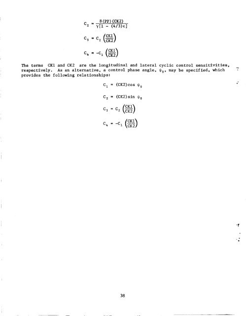
Y APPENDIX H COCKPIT CONTROLS AND CYCLIC CONTROL PHASING Cyclic, collective, and pedal controls may be specified from a zero position either centered or full left or down. The cyclic control position must be consistent between longitudinal and lateral cyclic, that is, centered or full left and <strong>for</strong>ward. The zero position <strong>of</strong> the collective or pedals may be specified independently. The table below lists the zero position, positive direction, and sign <strong>of</strong> the moment or <strong>for</strong>ce produced in the body system <strong>of</strong> axes. Alternate control zero position conventions are listed in parentheses. Control Longitudinal cyclic, 6, Lateral cyclic, 6, Collective, tic Pedals, 6p Zero position Positive direction Moment/<strong>for</strong>ce Centered Aft (full <strong>for</strong>ward) Centered Right (full left) Full down UP -Z Centered Right pedal +N (full left) <strong>for</strong>ward The control gearing, rigging, and cyclic control phasing are governed by the follow- ing equations : e, = C,6, + c, = C b +c, 'OTR 8 P The terms , C,, and C, are the constant or rigging terms <strong>for</strong> each 2- control. The terms C, through C, can be used to adjust <strong>for</strong> the phase angle between 4 the cyclic control input and the resulting flapping. These phase angle terms may be specified in two ways. First, a cyclic control phase relationship may be specified c on the basis <strong>of</strong> main rotor dynamic properties: c, = 1 - (8/3)~ + 2~~ 1 - (4/3)€ 37 (CK2) +M +L
c, = ‘C, (s) The terms CK1 and CK2 are the longitudinal and lateral cyclic control sensitivities, respectively. As an alternative, a control phase angle, Jlo, may be specified, which Y provides the following rela tionships: C, = (CK2)cos q0 . C, = (CK2)sin Jl,, c, = -c, (s) 38 .