Geologic And Hydrologic Factors Governing ... - Gunnison County
Geologic And Hydrologic Factors Governing ... - Gunnison County
Geologic And Hydrologic Factors Governing ... - Gunnison County

Create successful ePaper yourself
Turn your PDF publications into a flip-book with our unique Google optimized e-Paper software.
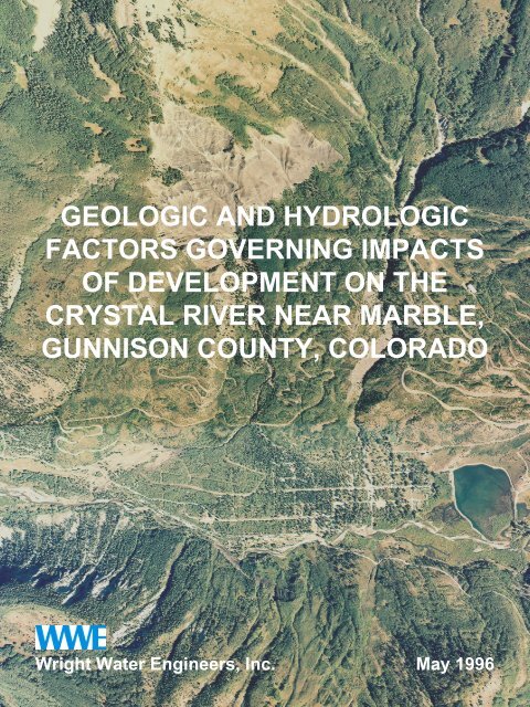
GEOLOGIC AND HYDROLOGIC<br />
FACTORS GOVERNING IMPACTS<br />
OF DEVELOPMENT ON THE<br />
CRYSTAL RIVER NEAR MARBLE,<br />
GUNNISON COUNTY, COLORADO<br />
Wright Water Engineers, Inc. May 1996
GEOLOGIC AND HYDROLOGIC<br />
FACTORS GOVERNING IMPACTS OF<br />
DEVELOPMENT ON THE CRYSTAL<br />
RIVER NEAR MARBLE, COLORADO<br />
GUNNISON COUNTY, COLORADO<br />
Prepared For:<br />
<strong>Gunnison</strong> <strong>County</strong>, Colorado<br />
Prepared By:<br />
John W. Rold and Kenneth R. Wright<br />
Wright Water Engineers, Inc.<br />
2490 W. 26th Avenue, Suite 100A<br />
Denver, Colorado 80211<br />
May 1996<br />
Job No. 951-110.000
TABLE OF CONTENTS<br />
Page<br />
1.0 INTRODUCTION ........................................................................................................ 1<br />
1.1 Goals of the Study ........................................................................................... 2<br />
1.2 Scope of Work ................................................................................................. 2<br />
1.3 Development History ....................................................................................... 3<br />
2.0 GEOLOGIC SETTING................................................................................................ 7<br />
2.1 <strong>Geologic</strong> History .............................................................................................. 8<br />
3.0 GEOLOGIC CONSTRAINTS TO DEVELOPMENT ................................................ 10<br />
3.1 Mudflows and Debris Flows........................................................................... 10<br />
3.1.1 Carbonate Creek Mudflow (Appendix A, Figure 4, Location 2b) . 11<br />
3.1.2 Slate Creek Mudflow (Appendix A, Figure 4, Location 2a) .......... 12<br />
3.2 Slope Instability Problems ............................................................................. 13<br />
3.2.1 Landslides..................................................................................... 14<br />
3.2.2 Potentially Unstable Slopes.......................................................... 15<br />
3.3 Avalanches .................................................................................................... 16<br />
4.0 HYDROLOGIC SETTING......................................................................................... 18<br />
4.1 Precipitation ................................................................................................... 19<br />
4.2 Surface Water Hydrology .............................................................................. 21<br />
4.2.1 Column Description ...................................................................... 23<br />
4.2.2 Analysis and Information Pending................................................ 24<br />
4.3 Groundwater Hydrology................................................................................. 26<br />
4.3.1 Morainal Deposits ......................................................................... 27<br />
4.3.2 Colluvial Deposits ......................................................................... 27<br />
4.3.3 Alluvial Deposits............................................................................ 28<br />
4.3.4. Alluvial Terraces ........................................................................... 28<br />
4.3.5. Alluvial and/or Debris Flow Fans .................................................. 28<br />
4.3.6 Spring Deposits ............................................................................ 29<br />
4.3.7 Groundwater ................................................................................. 29<br />
4.3.8 Faults and Joints........................................................................... 30<br />
4.4 Soil Permeability ............................................................................................ 31<br />
4.5 Groundwater Movement................................................................................ 35<br />
4.6 Groundwater Availability................................................................................ 36<br />
5.0 WATER QUALITY MANAGEMENT ......................................................................... 40<br />
5.1 Mechanics of Operation of Septic Leaching Systems................................... 40<br />
5.2 <strong>Factors</strong> Affecting Leaching Field Operation .................................................. 41<br />
5.3 Regulatory Aspects........................................................................................ 43<br />
5.4 Summary of <strong>Gunnison</strong> <strong>County</strong> Individual Sewage Disposal<br />
System (ISDS) Regulations........................................................................... 44<br />
5.5 Crystal River, Slate Creek <strong>And</strong> Carbonate Creek Classifications................. 46<br />
i
5.6 In-Stream Flow .............................................................................................. 47<br />
5.7 Critical Water Quality Parameters ................................................................. 48<br />
5.8 Allowable Pollutants....................................................................................... 49<br />
5.9 Typical Flows <strong>And</strong> Nitrate Loads................................................................... 50<br />
5.10 Pollution Constraints...................................................................................... 51<br />
5.10.1 Impact on the Surface Water Flow of the Crystal River ............... 52<br />
5.10.2 Impact on the Groundwater of the Crystal River Alluvial Aquifer. 52<br />
5.10.3 Impact on Carbonate Creek ......................................................... 53<br />
5.10.4 Impact on the Shale Bedrock ....................................................... 54<br />
5.10.5 Impact on the Colluvial Aquifer..................................................... 55<br />
5.11 ISDS Permit Application Rejection Scenarios............................................... 57<br />
6.0 EXPLANATION OF MAPS ....................................................................................... 59<br />
6.1 Topographic Map........................................................................................... 59<br />
6.2 Slope Map...................................................................................................... 60<br />
6.3 Plat Map......................................................................................................... 60<br />
6.4 Surficial and Engineering <strong>Geologic</strong> Map ....................................................... 60<br />
6.5 Slope Stability Evaluation .............................................................................. 61<br />
6.6 Specific Hazards............................................................................................ 61<br />
6.7 Soil Limitations to Leach Fields ..................................................................... 62<br />
6.8 Soil Permeability ............................................................................................ 62<br />
6.9 Development Limitations ............................................................................... 62<br />
7.0 CONCLUSIONS........................................................................................................ 63<br />
8.0 REFERENCES ......................................................................................................... 66<br />
APPENDIX A THE MARBLE AREA, A DEVELOPMENT FRONTIER<br />
APPENDIX B WELL PERMIT LOCATIONS<br />
APPENDIX C TABULATION OF WATER QUALITY TEST RESULTS 1979 TO<br />
1992, CRYSTAL RIVER AT REDSTONE, COLORADO<br />
ii
LIST OF FIGURES<br />
FIGURE 1 REDSTONE AVERAGE/YEAR PRECIPITATION<br />
FIGURE 2 MAXIMUM UNIT FLOOD DISCHARGES VERSUS AREA IN SQUARE<br />
MILES<br />
FIGURE 3 SEDIMENT YIELD RELATIONSHIP TO TOPOGRAPHIC RELIEF (STEEP-<br />
NESS)<br />
FIGURE 4 YIELD, DEPTH, AND WATER LEVELS OF WELLS, MARBLE, COLORADO<br />
LIST OF TABLES<br />
TABLE 1 REDSTONE WEATHER STATION PRECIPITATION<br />
TABLE 2 SNOW SURVEY MEASUREMENTS<br />
TABLE 3 CARBONATE CREEK LOW FLOW HYDROLOGY<br />
TABLE 4 BASIN CHARACTERISTICS FOR SELECTED STREAMS<br />
TABLE 5 DECREED MINIMUM FLOWS FOR THE CRYSTAL RIVER<br />
TABLE 6 SUMMARY FLOW DATA FOR THE CRYSTAL RIVER<br />
TABLE 7 CWQCC NUMERIC STANDARDS FOR NITRATE IN GROUNDWATER<br />
LIST OF DRAWINGS (Following Text)<br />
DRAWING 1 TOPOGRAPHIC MAP AND LOCATION INDEX<br />
DRAWING 2 SLOPE MAP<br />
DRAWING 3 PLAT MAP<br />
DRAWING 4 SURFICIAL AND ENGINEERING GEOLOGIC MAP<br />
DRAWING 5 SLOPE STABILITY EVALUATION<br />
DRAWING 6 SPECIFIC HAZARDS<br />
DRAWING 7 SOIL LIMITATIONS TO LEACH FIELDS<br />
DRAWING 8 SOIL PERMEABILITY<br />
DRAWING 9 DEVELOPMENT LIMITATIONS<br />
iii
GEOLOGIC AND HYDROLOGIC FACTORS GOVERNING<br />
IMPACTS OF DEVELOPMENT ON THE CRYSTAL RIVER<br />
NEAR MARBLE, COLORADO<br />
GUNNISON COUNTY, COLORADO<br />
1.0 INTRODUCTION<br />
This report provides an evaluation of the geologic, topographic, and hydrologic factors governing<br />
the impacts of development and presents a database for evaluating the propriety of future develop-<br />
ment in the Marble area of the Crystal River Valley. Spatial data established for the defined study<br />
area is compatible with the <strong>Gunnison</strong> <strong>County</strong> ARC/INFO geographic information system (GIS) da-<br />
tabase. The database and report provide a suitable basis to help establish appropriate land use and<br />
environmental policies and regulations for future development, including the appropriate use of in-<br />
dividual sewage disposal systems (ISDSs).<br />
The subject Marble Ski Area Filings are located in Sections 13, 14, 23, 24, 25, 26, 27, and 28 of<br />
Township 11 South, Range 88 West of the 6th P.M. in <strong>Gunnison</strong> <strong>County</strong>, Colorado as illustrated on<br />
Drawing 1.<br />
The subject study area includes the Town of Marble and the following Planned Unit Developments<br />
(PUDs) in unincorporated lands: Marble Ski Area Filings 1, 2, 3, 4, 5, 7, MSA Condominium Fil-<br />
ing, Hermits Hideaway, and the Crystal River Filing. Marble Ski Area Filings plotted during the<br />
early 1970s were projected to have approximately 2,400 single-family lots, 600 multi-family units,<br />
and a small ski area. A typical, single family lot size is approximately 0.3 acres. In the past two<br />
years, <strong>Gunnison</strong> <strong>County</strong> has noted a significant increase in development within these filings.<br />
Planned central sewer and water facilities were thwarted by bankruptcy of the developer and never<br />
materialized. Water supply for this development must be satisfied by individual wells or hauling of<br />
water. Reliance on septic systems may impact groundwater and surface water quality. Investiga-<br />
tions by the Colorado <strong>Geologic</strong>al Survey (CGS) (Rogers and Rold 1972) and Thorne Ecological In-<br />
stitute (Robinson and Cochran 1973), coupled with 1995 site inspections by the authors (Wright and<br />
951-110.000 Wright Water Engineers, Inc. Page 1
<strong>Geologic</strong> <strong>And</strong> <strong>Hydrologic</strong> <strong>Factors</strong> <strong>Governing</strong> Impacts Of Development<br />
On The Crystal River Near Marble, Colorado<br />
<strong>Gunnison</strong> <strong>County</strong>, Colorado<br />
Rold), indicate that debris flows, landslides, avalanches, flooding, and potentially unstable steep<br />
slopes prevent or severely restrict construction in much of the platted area.<br />
1.1 Goals of the Study<br />
The goals of the study are to establish a topographic, geotechnical/water quality database compatible<br />
with ARC/INFO that can be used to aid the county in creating appropriate land use and environ-<br />
mental policies and regulations for future development, including the reasonable use of ISDSs.<br />
Available information pertaining to geotechnical factors associated with road construction, building<br />
site development, slope stability, and soil creep are summarized and the data incorporated into a spe-<br />
cial database. The study results are intended to aid the county in determining policies and decisions<br />
for defining conformable land use for specific areas, identifying primary density considerations,<br />
mapping non-developable areas, establishing a future buildout scenario, evaluating infrastructure<br />
design, and cataloging alternative construction techniques.<br />
1.2 Scope of Work<br />
The following summarizes the approved Scope of Work aimed at addressing and achieving the study<br />
goals:<br />
Task 1. Review existing published and unpublished geological, geotechnical, and hydrologic<br />
data relevant to the area.<br />
Task 2. Compile and review geotechnical data submitted to <strong>Gunnison</strong> <strong>County</strong> and/or CGS,<br />
local sanitarians, or Colorado Department of Public Health and Environment<br />
(CDPHE) by previous development proponents.<br />
Task 3. Meet with <strong>Gunnison</strong> <strong>County</strong> personnel and leaders of the Marble community to dis-<br />
cuss the project.<br />
Task 4. Compilation of available water quality data from the Crystal River watershed.<br />
951-110.000 Wright Water Engineers, Inc. Page 2
<strong>Geologic</strong> <strong>And</strong> <strong>Hydrologic</strong> <strong>Factors</strong> <strong>Governing</strong> Impacts Of Development<br />
On The Crystal River Near Marble, Colorado<br />
<strong>Gunnison</strong> <strong>County</strong>, Colorado<br />
Task 5. Using computer technology compatible with ARC/INFO, prepare a digitized topog-<br />
raphic map from the best available topographic source, and utilizing that data, pre-<br />
pare a slope map of the area.<br />
Task 6. A field inspection of the Marble Ski Area Filings by environmental geologist, Mr.<br />
John Rold, and civil engineer, Mr. Kenneth Wright.<br />
Task 7. Utilizing the assembled data, categorize those areas which are determined to be un-<br />
suitable for septic tank/leaching field systems and define those areas on the<br />
ARC/INFO map.<br />
Task 8. Evaluate the geotechnical characteristics that would relate to slope stability, natural<br />
hazards, road construction, building site development, and soil creep. This would re-<br />
sult in a map showing areas that could be developed with minimal reviews and<br />
evaluation by the counties and those areas which could be developed only after care-<br />
ful detailed geotechnical and engineering studies of the site.<br />
Task 9. Consolidate the above data, evaluations and findings in regard to conformable land<br />
use, density considerations, non-developable areas; prepare a basis for future build-<br />
out scenarios, considerations for infrastructure design, and identification of alterna-<br />
tive construction techniques.<br />
Task 10. Utilizing the above and available data, determine the accumulative impacts of septic<br />
systems on the water quality of the Crystal River.<br />
1.3 Development History<br />
Although the climate and the scenery have attracted many people to the Marble area since its earliest<br />
settlement, the first attempt to commercialize this resource occurred in 1956 when Mr. Wade Loud-<br />
ermilk assembled several hundred acres of land and formed the Crystal River Enterprises. The first<br />
recorded attempt to evaluate the area for commercial ski development occurred in 1967 when Crys-<br />
951-110.000 Wright Water Engineers, Inc. Page 3
<strong>Geologic</strong> <strong>And</strong> <strong>Hydrologic</strong> <strong>Factors</strong> <strong>Governing</strong> Impacts Of Development<br />
On The Crystal River Near Marble, Colorado<br />
<strong>Gunnison</strong> <strong>County</strong>, Colorado<br />
tal Basin Outlife, Ltd., was formed and contracted with Sno-Engineering and Mr. Willie Schaeffler<br />
to evaluate the ski area potential.<br />
In 1969, the Marble Ski Area, Inc., was formed and assembled 1,950 acres. They developed a mas-<br />
ter plan envisioning up to 8,800 dwelling units on private land and a major ski development utilizing<br />
4,600 acres of federal lands covering the slopes of Mt. Daly, Arkansas Mountain, Sheep Mountain,<br />
and Buckskin and Coyote Basins. This plan would have resulted in a major ski complex as large as<br />
Vail, Aspen, or any now developed in the state.<br />
In late 1970, the CGS became aware of this major development activity. Knowledge of the local<br />
geology and a cursory investigation indicated numerous serious geological constraints to the devel-<br />
opment and caused understandable serious concern. The CGS contacted the developer to determine<br />
his exact development plans and began a crash program of geological investigation. When the pre-<br />
liminary results outlining the serious geologic problems affecting the development were relayed to<br />
the developer, a confrontation arose. It became apparent that a readily available public document<br />
was needed to objectively portray the geologic problems of the area to the developer, state, and local<br />
decision-makers, investors, and the potential lot buying public. The CGS report, Engineering Geo-<br />
logic <strong>Factors</strong> of the Marble Area, was published in June 1972. It became a key document in a battle<br />
between the opponents and proponents of the Marble Ski Area. At that time, Senate Bill 35 had not<br />
been passed and <strong>Gunnison</strong> <strong>County</strong> did not have adequate subdivision regulations or staff to address<br />
such a major problem. Several of the early filings had already been approved. At that time, the<br />
CGS’s only statutory authority for involvement was its enabling act which charged it to “delineate<br />
areas of natural geologic hazard which could affect the safety of or cause economic loss to the citi-<br />
zens of the state,” and the charge, “to provide advice and counsel to all agencies of state and local<br />
government on geologic problems.” In the early stages of the confrontation, <strong>Gunnison</strong> <strong>County</strong> was<br />
not aware they had a geologic problem and had not asked for the advice and counsel.<br />
The basic concern arose from a comparison of the master plan document and geological conditions<br />
that would affect those activities. Particularly, the Slate Creek mudflow had been platted for resi-<br />
dential development and an area of commercial development. Numerous lots had already been sold.<br />
951-110.000 Wright Water Engineers, Inc. Page 4
<strong>Geologic</strong> <strong>And</strong> <strong>Hydrologic</strong> <strong>Factors</strong> <strong>Governing</strong> Impacts Of Development<br />
On The Crystal River Near Marble, Colorado<br />
<strong>Gunnison</strong> <strong>County</strong>, Colorado<br />
East of Carbonate Creek near the proposed ski area base facilities, numerous condominium sites<br />
were platted on or adjacent to active landslides, and on unstable slopes. In May 1973, when a catas-<br />
trophic landslide took out a subdivision road and several condominium sites, the material ended up<br />
in Beaver Lake several hundred feet below. In the upper Slate Creek drainage, high density devel-<br />
opment was planned close to Gallo Bluff with little credence being given by the master plan to ava-<br />
lanches, mudflows, and potential landslides. Additionally, a school site was platted along the Crys-<br />
tal River and within the Carbonate Creek mudflow deposition zone. Condominium units were also<br />
master planned in the avalanche terrain south of the Marble town site.<br />
On September 19, 1972, a mudflow on Slate Creek buried a subdivision road and covered numerous<br />
platted lots up to a depth of 3 to 4 feet. This event more than anything else demonstrated to the de-<br />
veloper that geology was not an academic exercise and would be the paramount design considera-<br />
tion for planning this development. This event marked a change in dealings with the developer, who<br />
began to buy back lots that had been sold in the Slate Creek mudflow area and other hazardous ar-<br />
eas. In an attempt to revise the development to conform to the serious geological problem areas, the<br />
total area was placed in a PUD with platting concentrated in the better areas, and with many of the<br />
hazard areas placed in an undisturbed or greenbelt status. <strong>Gunnison</strong> <strong>County</strong> became cognizant of<br />
geologic problems and refused to approve any plats or construction plans until they had been inves-<br />
tigated and approved by the CGS. The ultimate plan to utilize some 4,600 acres of U.S. Forest Ser-<br />
vice (USFS) land for ski terrain and lift development was turned down by the USFS, and a more<br />
modest plan utilizing approximately 600 acres on the slopes of Mt. Daly was formally proposed.<br />
Earlier, a 4,200-foot chair lift and three ski trails had been constructed on private land. A study of<br />
environmental, ecological, and geological factors affecting the total development and the USFS’s<br />
special use permit area was contracted to Thorne Ecological Institute of Boulder in 1973. Environ-<br />
mentalists, other opponents to the ski area, and governmental agencies raised questions of the impact<br />
on wildlife, particularly elk and deer winter range, proximity to the neighboring proposed Snowmass<br />
Wilderness area, air and water pollution, and numerous other factors. The State Land Use Commis-<br />
sion conducted an investigation of the area. Numerous charges of improper and illegal sales tech-<br />
niques were leveled at the developer (Schneider 1974). Several lots were allegedly illegally sold<br />
from unplatted and unapproved filings. The state Real Estate Commission and the Securities Ex-<br />
951-110.000 Wright Water Engineers, Inc. Page 5
<strong>Geologic</strong> <strong>And</strong> <strong>Hydrologic</strong> <strong>Factors</strong> <strong>Governing</strong> Impacts Of Development<br />
On The Crystal River Near Marble, Colorado<br />
<strong>Gunnison</strong> <strong>County</strong>, Colorado<br />
change Commission began investigations. Identified geologic hazards and other adverse publicity<br />
from many different angles exerted a serious drop in land sales and frightened away potential inves-<br />
tors.<br />
In 1973, the area was reorganized into the Marble Holding Company, Inc., with a change in man-<br />
agement and an infusion of new personnel, new consultants, new enthusiasm, and new capital. The<br />
new corporation was not successful in overcoming the myriad problems and in September 1974, pe-<br />
titioned for bankruptcy. In 1977, the Federal Bankruptcy Court attempted to liquidate the land assets<br />
in order to satisfy the many creditors.<br />
A major factor in the problems facing potential land development in the Marble area is the situation<br />
that most of the tracts did not go through the Senate Bill 35 subdivision process. That statutory sys-<br />
tem of geologic investigation by the developer’s consultant, review by the CGS, evaluation by the<br />
county staff and approval by the <strong>County</strong> Commissioners was detoured when upon bankruptcy of the<br />
developer, separate tracts of land were sold by the bankruptcy court. Lots and tracts were sold with-<br />
out warranty to land speculators, out-of-state buyers, retirees, summer home candidates, and people<br />
just wanting a beautiful piece of Colorado. Many lots have been bought and sold several times with<br />
no thought or concern for geologic hazards, access, physical water availability and quality, or septic<br />
tank suitability. Although developable lots exist in the area, many parcels present significant risks<br />
and even insurmountable problems for a home builder.<br />
951-110.000 Wright Water Engineers, Inc. Page 6
2.0 GEOLOGIC SETTING<br />
<strong>Geologic</strong> <strong>And</strong> <strong>Hydrologic</strong> <strong>Factors</strong> <strong>Governing</strong> Impacts Of Development<br />
On The Crystal River Near Marble, Colorado<br />
<strong>Gunnison</strong> <strong>County</strong>, Colorado<br />
To fully understand the problems of the Marble area, one must understand the geologic setting. Di-<br />
astrophism (mountain building) and geomorphic processes have shaped the area’s topography and,<br />
in combination, control the movement of fluids. <strong>Geologic</strong> formations of the area control its topog-<br />
raphic shape and the movement of fluids as certainly as the muscles and bone structure of the human<br />
body determine its anatomy and the movement of the fluids within it.<br />
Regionally, the area lies between the southern edge of the Piceance Creek Basin to the west and the<br />
Sawatch Uplift to the east. Locally, the study area lies on the northeast flank of a northwesterly-<br />
plunging gentle syncline. The syncline itself has been modified by the Treasure Mountain Stock, the<br />
Ragged Mountain Laccolith, and the associated Raspberry Creek Phacolith, as well as the Snow-<br />
mass Stock and the major Elk Range thrust fault to the east. These intrusions have intensely meta-<br />
morphosed the sedimentary rocks around them and have mildly metamorphosed the Mesaverde and<br />
Mancos sediments in the study area. The underlying bedrock formations of Mesaverde and Mancos<br />
Formations in the study area dip gently some 18 to 25 degrees to the southwest and to the west.<br />
Most of the underlying bedrock formations are covered to varying thickness with surficial deposits<br />
of the glacial moraine, landslides, mudflows, talus, colluvium, and alluvium (Drawing 4). The mo-<br />
rainal deposits form a varying thickness of material blanketing the valley walls, particularly on the<br />
gentler, south-facing slopes. Colluvium, which is formed from the weathering and downward gravi-<br />
tational movement of other surficial deposits and bedrock, blankets the area in many locations. De-<br />
bris flow and mudflow deposits occur several places.<br />
The Cretaceous Mancos Shale bedrock can be seen where it is exposed in the canyon of Carbonate<br />
Creek, the lower slopes of Gallo Bluff, and the steep slopes northeast of the town site. The Mancos<br />
consists of fairly massive, dark gray, laminated, silty shale. The Cretaceous Mesaverde Formation,<br />
exposed in the upper portions of Gallo Bluff, extends to the west to the town site of Placita, and con-<br />
sists of interbedded sandstone, shale and thin to thick coal beds. Coal beds were mined in the his-<br />
toric past, but no coal mines are known in the study area.<br />
951-110.000 Wright Water Engineers, Inc. Page 7
<strong>Geologic</strong> <strong>And</strong> <strong>Hydrologic</strong> <strong>Factors</strong> <strong>Governing</strong> Impacts Of Development<br />
On The Crystal River Near Marble, Colorado<br />
<strong>Gunnison</strong> <strong>County</strong>, Colorado<br />
To the southeast, the Treasure Mountain Dome exposes a full section of Mesozoic and Paleozoic<br />
formations down to the Precambrian gneiss and Tertiary granite-porphyry core. Although the Yule<br />
Marble does not crop out in the study area, it is important historically for it gave the town its name<br />
and provided its first industry. The Yule Marble, which is metamorphosed Leadville Limestone<br />
crops out high on the southwest and the northwest flanks of the Treasure Mountain Dome. Marble<br />
was produced commercially from the late 1800s until approximately the mid-1940s when the town<br />
and mill were damaged by a major mudflow. The quarry re-opened for commercial production in<br />
1990, and is currently shipping marble.<br />
Numerous avalanche tracks exist along the Gallo Bluff and the steep slopes to the south of the Crys-<br />
tal River (Drawing 6). Mears (1975) describes the Crystal River paths as medium-sized with start-<br />
ing zones of 10 to 30 acres and having vertical drops of less than 3,000 feet. Accumulation zones,<br />
however, are oriented on the lee side of ridges and avalanches occur relatively often. A second<br />
group of much larger avalanches occurs in the vicinity of Elk Mountain and Mount Daly to the east<br />
and north of Marble.<br />
2.1 <strong>Geologic</strong> History<br />
The classical, complete geologic history of the area has been discussed previously by Rogers and<br />
Rold (1972), Robinson and Cochran (1973), and Rold (1977), as well as Gaskill and Godwin (1966).<br />
Therefore, only those geologic processes which relate directly to the problems of the study area will<br />
be discussed. The pertinent geologic history began approximately 100 million years ago in Creta-<br />
ceous time. A wide-spread sea covered the area with the deposition consisting mostly of dark gray<br />
mud approximately 4,000 feet in thickness. This mud later lithified and became the shales of the<br />
Mancos Formation which are well-exposed in the lower part of Gallo Bluff, along the canyon of<br />
Carbonate Creek and the steep slopes to the northeast of Marble.<br />
During one of the retreats of this Cretaceous sea, the shoreline advanced northeastward across the<br />
area. Widespread forest and swamp conditions existed on the landward side of the ancient shoreline.<br />
As these forests and swamp deposits were later buried and lithified, they became the coal beds of the<br />
Mesaverde Formation. Both the Mesaverde Formation, and especially the Mancos Shale are argilla-<br />
951-110.000 Wright Water Engineers, Inc. Page 8
<strong>Geologic</strong> <strong>And</strong> <strong>Hydrologic</strong> <strong>Factors</strong> <strong>Governing</strong> Impacts Of Development<br />
On The Crystal River Near Marble, Colorado<br />
<strong>Gunnison</strong> <strong>County</strong>, Colorado<br />
ceous (made of clay). As such, they are easily eroded because their properties are severely weak-<br />
ened by the presence of water. These underlying geologic characteristics contribute significantly to<br />
the slope instability and provide much of the material for the numerous landslides and mudflows in<br />
the area.<br />
Some 70 million years ago, mountain-building forces formed the basic geologic framework of basins<br />
and mountain uplifts for the entire Rocky Mountains and the underlying structural blueprint of the<br />
Marble area.<br />
Later, several igneous rock masses, particularly the Treasure Mountain Stock, the Snowmass Stock,<br />
the Ragged Mountain Laccolith, and the Raspberry Creek Phacolith intruded the area. These large,<br />
molten masses of rock provided the heat and pressure to metamorphose or alter the thick limestone<br />
beds of the Leadville Formation into the Yule Marble, and, to a certain extent, change Mesaverde<br />
coals from moderate grade bituminous to high grade coking coals, and even in some cases anthra-<br />
cite. This metamorphism likewise hardened the Mancos Shale and Mesaverde Formation in many<br />
parts of the study area.<br />
During the Pleistocene or Ice Age, from approximately 1 million years ago to 10 thousand years ago,<br />
the mountain ranges of the area contained large ice caps from which major glaciers moved down the<br />
major high mountain valleys. Four major glacial episodes occurred in the Rockies during that pe-<br />
riod. Glaciers coming down the Crystal River Valley carved the valley into its present general<br />
shape. These glaciers, in many places, formed the oversteepened, unstable valley walls in the soft<br />
bedrock of the Mancos and Mesaverde Formations and left a thin veneer of morainal material. This<br />
set the stage for the post-glacial slope instability and mass wasting problems that plague the area yet<br />
today. In the last 10 thousand years, the processes of erosion and mass wasting by landslides and<br />
debris flows have combined to form the present topography of the Marble area.<br />
951-110.000 Wright Water Engineers, Inc. Page 9
<strong>Geologic</strong> <strong>And</strong> <strong>Hydrologic</strong> <strong>Factors</strong> <strong>Governing</strong> Impacts Of Development<br />
On The Crystal River Near Marble, Colorado<br />
<strong>Gunnison</strong> <strong>County</strong>, Colorado<br />
3.0 GEOLOGIC CONSTRAINTS TO DEVELOPMENT<br />
<strong>Geologic</strong> constraints affecting development in the Marble area are tied directly to the basic processes<br />
of material weathering, erosion, transportation, and deposition. The effects of these processes are<br />
magnified because of the unique geologic setting of the Crystal River valley. These basic processes<br />
have seriously constrained development since the first human activities in the Marble area. Such<br />
processes may be referred to as geologic hazards when catastrophic events devastate facilities and<br />
infrastructure and/or present human safety implications. The geologic setting and associated mor-<br />
phological processes, perhaps more than any other components, influence development locations,<br />
infrastructure alignments, and maintenance needs, and significantly add to the total development<br />
cost.<br />
Engineering geologic factors have seriously constrained development since man’s first activities in<br />
the valley. Although these factors have become significant geologic hazards when they interacted<br />
with man’s activities, they have also definitely affected the location, construction costs, and mainte-<br />
nance costs of transportation and development facilities, and exert strong, constant, and economic<br />
pressures on all development activities. Such engineering geology terms as shear strength, angle of<br />
repose, excavatibility and erodibility, though unknown words to early workers, have continually af-<br />
fected the cost and safety of all of man’s construction activities.<br />
Several specific engineering geologic factors have been evaluated and mapped by the CGS (Rogers<br />
and Rold 1972), and Robinson & Cochran as consultants for the ski area developers (Drawing 4).<br />
These studies have been reevaluated for this investigation. These geologic factors which constitute<br />
geologic hazards are discussed under three major categories: (1) mudflows and debris flows, (2)<br />
slope instability, and (3) avalanches.<br />
3.1 Mudflows and Debris Flows<br />
Rogers and Rold (1972) described the origin and mechanics of Marble’s alpine-type mudflows as<br />
follows:<br />
951-110.000 Wright Water Engineers, Inc. Page 10
<strong>Geologic</strong> <strong>And</strong> <strong>Hydrologic</strong> <strong>Factors</strong> <strong>Governing</strong> Impacts Of Development<br />
On The Crystal River Near Marble, Colorado<br />
<strong>Gunnison</strong> <strong>County</strong>, Colorado<br />
“With a torrential or cloudburst type rainstorm, rapid water runoff occurs, generally<br />
accompanied by debris avalanching of the upper slopes. The water and debris obtained<br />
high velocities . . . incorporating the coarse lag deposits which accumulate at<br />
very steep angles of repose in the steep intermittent stream beds of the lower parts of<br />
the high slopes. The mixing of storm runoff, soil and rock debris forms a viscous<br />
slurry of the approximate consistency of a wet concrete mix . . . A rather high velocity<br />
is maintained by the channeling effect, the steep gradient and the pressure of the<br />
moving mass from above and behind. When this stream of mud reaches the lower<br />
slopes, it spreads out, loses velocity and deposits much of its coarse load.”<br />
The major Marble mudflow or debris flow fan (frequently called an alluvial fan and shown as such<br />
on several maps) is one of the more apparent features to the geologist or layman visiting the area,<br />
and has figured prominently in its history. The major composite flow (Appendix A, Figures 2 and 4)<br />
was first mapped by Gaskill (1966) and is readily apparent on aerial photographs (Appendix A, Fig-<br />
ure 5). The fan-shaped mudflow deposit which is approximately a mile long, spreads out into the<br />
Crystal River Valley to a width of approximately a mile and a half. Rogers and Rold (1970) calcu-<br />
lated the maximum thickness of the mudflow complex as approximately 175 feet. Field observa-<br />
tions indicate the older part of the fan was deposited by debris flows from the ancestral Carbonate<br />
Creek at a location somewhere between the present locations of Carbonate Creek and Slate Creek.<br />
Next, probable major landslide activity originating from Gallo Bluff (Appendix A, Figure 7), or pos-<br />
sibly a glacier, diverted Carbonate Creek eastward to its present channel. Thereafter, the younger<br />
Slate Creek drainage developed on the western edge of the upper reaches of the fan. In order to pro-<br />
tect the town from mudflows, the townspeople in 1920 diverted the main Slate Creek channel to the<br />
western extremities of the fan.<br />
The major mudflow fan postdates the glacial retreat and, therefore, is no older than approximately<br />
10,000 years. The deposition of the fan has deflected the Crystal River southward and caused the<br />
upstream damming that was later modified by the development of Beaver Lake. Erosion of the<br />
south canyon wall by the deflected stream has triggered a landslide.<br />
3.1.1 Carbonate Creek Mudflow (Appendix A, Figure 4, Location 2b)<br />
Carbonate Creek descends from a steep and sizable drainage basin (approximately 3,700 acres) on<br />
the slopes of Mt. Daly and Elk Mountain to the north. The upper channel is entrenched and actively<br />
951-110.000 Wright Water Engineers, Inc. Page 11
<strong>Geologic</strong> <strong>And</strong> <strong>Hydrologic</strong> <strong>Factors</strong> <strong>Governing</strong> Impacts Of Development<br />
On The Crystal River Near Marble, Colorado<br />
<strong>Gunnison</strong> <strong>County</strong>, Colorado<br />
eroding a steep, incised canyon in the Mancos Shale. As it emerges from the steep canyon and its<br />
gradient flattens, coarse debris carried by the water is first deposited in a fan. Devastating mud<br />
floods have been recorded in 1936, 1941, and 1945. The “undeveloped” area in the center of the<br />
town represents the area devastated by the 1941 and 1945 mudflows (Appendix A, Figure 8). Some<br />
of the more recent floods caused little or no damage because this central area had not been rebuilt.<br />
The lighter color of the Carbonate Creek mudflow reflects an additional provenance of igneous and<br />
Pennsylvanian sedimentary rocks not available to the Slate Creek drainage which drains only Man-<br />
cos and Mesaverde terrain.<br />
3.1.2 Slate Creek Mudflow (Appendix A, Figure 4, Location 2a)<br />
Slate Creek heads along the base of Gallo Bluff and follows an entrenched course along the western<br />
edge of the major mudflow deposits. This highly erosive channel (Appendix A, Figure 9) with over-<br />
steepened banks of old landslide and mudflow debris from the Mesaverde and Mancos is potentially<br />
very unstable. Both the rapidly wasting Gallo Bluff and the channel banks provide abundant sources<br />
for mudflow debris during strong runoff and periods of thunderstorms. Where the channel emerges<br />
from its entrenched course, some 2,000 feet north of the Crystal River, the gradient decreases and<br />
the mudflow debris is deposited with the coarsest material being deposited closest to the mouth of<br />
the channel. Blocks in excess of 6 feet in diameter are common (Appendix A, Figure 10). Fine<br />
muds are deposited all the way to the Crystal River. Studies by Rogers and Rold (1972) of aerial<br />
photographs of different ages, vegetation, topography, and the mudflow deposits, indicated a Slate<br />
Creek debris flow frequency on an average of approximately one every two years. Historic events<br />
have borne out those predictions. A debris flow on Slate Creek in September of 1972 which buried<br />
many platted lots and two subdivision roads was a major factor in convincing the developer that geo-<br />
logic factors were predictable and should be taken into account in development.<br />
Many developers or home builders see the apparent channel of mudflows such as Slate Creek and<br />
Carbonate Creek as permanent features and feel that by avoiding that channel with a reasonable<br />
right-of-way, the remainder of the fan could be built upon with impunity. In the Ski Area Filings,<br />
for example, residential lots were originally platted and sold at a density of 3 to 4 per acre across<br />
much of the Slate Creek mudflow (Appendix A, Figure 10). The history of this and other fans indi-<br />
951-110.000 Wright Water Engineers, Inc. Page 12
<strong>Geologic</strong> <strong>And</strong> <strong>Hydrologic</strong> <strong>Factors</strong> <strong>Governing</strong> Impacts Of Development<br />
On The Crystal River Near Marble, Colorado<br />
<strong>Gunnison</strong> <strong>County</strong>, Colorado<br />
cate, however, that over time these channels migrate back and forth across the entire fan surface<br />
much like a fire hose gone wild. The channel of Slate Creek has changed its course over the fan<br />
several times since the 1972 study. Inspection of early photographs and detailed topography and our<br />
field evaluation of the Marble fan show numerous old channels throughout the fan.<br />
Debris flows of lesser magnitude but with the capability of considerable damage also occur at the<br />
mouths of Raspberry and Milton Creeks south of the landing strip. Serious flooding and debris<br />
deposition have been noted since development began.<br />
Most of the drainages into the Crystal River downstream from Marble show strong mudflow and<br />
debris fan deposition, and have exerted considerable adverse impact on the roads and potential<br />
building sites.<br />
3.2 Slope Instability Problems<br />
Slope instability problems include deep soil creep, old landslides in various stages of instability<br />
which could easily be reactivated by construction, active moving landslide masses and potential un-<br />
stable slopes where new slides could be activated by construction activity. Active landslides are<br />
relatively easily mapped. Old landslides which have undergone erosion and varying degrees of<br />
modification are more difficult to define. Precise delineation and prediction of the future behavior of<br />
potentially unstable slopes so common at Marble can be very difficult. Comparisons with similar<br />
geologic, topographic, and moisture conditions in previously failed areas can be useful. Many times<br />
evaluation becomes a complex geometric problem of relating attitudes of weakness planes in the<br />
rock to the original and post-construction ground surface taking into account future changes in<br />
groundwater conditions. A liberal use of “geo-logic” (earth study-horse sense) provides consider-<br />
able insight into predicting future problems and many times is more reliable than precise mathemati-<br />
cal calculations. Although potentially unstable slopes may appear quite innocent, they may be more<br />
hazardous to future activities than slopes that have stabilized after previous failure.<br />
951-110.000 Wright Water Engineers, Inc. Page 13
3.2.1 Landslides<br />
<strong>Geologic</strong> <strong>And</strong> <strong>Hydrologic</strong> <strong>Factors</strong> <strong>Governing</strong> Impacts Of Development<br />
On The Crystal River Near Marble, Colorado<br />
<strong>Gunnison</strong> <strong>County</strong>, Colorado<br />
The largest landslide deposit in the area occurs between Gallo Bluff and Carbonate Creek, northwest<br />
of the town site (Appendix A, Figures 4 and 6). As mapped by Gaskill (1966), Rogers and Rold<br />
(1972), and Robinson and Cochran (1973), it extends more than a mile in length. The main mass of<br />
this old landslide now seems quite stable, although significant construction and drainage changes<br />
could easily reactivate parts of the slide. The complex origin of the slide mass is poorly understood.<br />
It may have originated as one or a series of major catastrophic landslides from Gallo Bluff. Such a<br />
future catastrophic slide from the Gallo Cliffs is possible, and would imperil future development<br />
near its base.<br />
North of the landing strip, a large anomalous area of talus and igneous bedrock is delineated and<br />
crossed by landslide-like scarps. Some of the valleys along the scarps roughly parallel the slope and<br />
are 100 feet wide and 30 feet deep. Very probably, the disturbed area is underlain by large bedrock<br />
blocks which are slowly sliding down the hill along bedding planes in the Mesaverde or sloping<br />
planes of weakness within or below the Raspberry Creek Phacolith. The overlying coarse talus ex-<br />
hibits many characteristics of rock glaciers. Patterns of leaning trees indicate a slow but continuing<br />
movement that could be markedly accelerated by excavations in the toe of the slopes.<br />
A series of both active and inactive bedrock slides in the Mancos occurs along the east bank of Car-<br />
bonate Creek (Appendix A, Figure 4, Location 1a to 1e). Here, the Mancos Shale and its planes of<br />
weakness dip gently to the northwest into the deeply incised canyon of Carbonate Creek. Detailed<br />
mapping by Robinson and Cochran (1973) indicated discontinuous but prominent landslide release<br />
fractures along a zone nearly a mile long east of and paralleling the creek. Each of these slides and<br />
potential failures could have provided serious problems to the condominiums and high density facili-<br />
ties once planned at the base of the ski lifts.<br />
One small, active, and growing landslide (Appendix A, Figure 4, Location 1c) triggered several in-<br />
teresting reactions. The previous developers recognized the slide from Gaskill’s mapping. They<br />
avoided the slide itself but planned multistory condominiums immediately to the south, east, and<br />
north without determining the ultimate extent of the slide failure. During a wet period in May 1973,<br />
951-110.000 Wright Water Engineers, Inc. Page 14
<strong>Geologic</strong> <strong>And</strong> <strong>Hydrologic</strong> <strong>Factors</strong> <strong>Governing</strong> Impacts Of Development<br />
On The Crystal River Near Marble, Colorado<br />
<strong>Gunnison</strong> <strong>County</strong>, Colorado<br />
the slide began to move rapidly and erratically (as much as several feet of movement were observed<br />
in one day). Townspeople immediately grasped the potential of a major block of Mancos Shale fal-<br />
ling into the stream, temporarily creating a dam. The dam could quickly overtop and plunge a mud<br />
and debris flood into the Marble town site. Unpalatable choices faced the decision-makers in pre-<br />
paring for the possible event. The lower channel flow might be diverted to either the east or the<br />
west, thus condemning that part of the remaining town site, or the channel could be left alone in<br />
hopes the flow would remain in the present channel and harmlessly cover that portion of the town<br />
site previously destroyed in the 1941 and 1945 mudflows. Fortunately, the wet period ended before<br />
total collapse of the slide mass, and it returned to slow, periodic movement. Hopefully, Carbonate<br />
Creek’s continued erosion of the toe may periodically remove small portions of much of the slide<br />
mass and avoid a possible catastrophic release. One must be aware that the risk still exists. Some-<br />
time in the future a large slide could dam the canyon of Carbonate Creek. Overtopping of that dam<br />
could cause a catastrophic debris flow into the town site. A large debris flow could easily plug the<br />
present channel and divert itself either to the east or west.<br />
3.2.2 Potentially Unstable Slopes<br />
A large typical area of unstable slopes (Appendix A, Figure 4, Location 1f) has been mapped on the<br />
slopes northeast of the town site. Although we saw little evidence of past failures during the site vis-<br />
its (Fall 1995), the steep slopes, weak, severely-jointed Mancos Shale bedrock and spring snow melt<br />
saturation indicate serious potential slope stability problems. The prediction of Rogers and Rold<br />
(1972),<br />
“Most slopes in this part of Mt. Daly range form 30% to 60%. Excavation of any cut<br />
slopes which will have the effect of steepening existing slopes and daylighting weak<br />
surficial layers will pose serious long-range stability problems.”<br />
came to pass May 14, 1975. A section of new road approximately 150 feet long and part of two<br />
condominium sites released as a wet landslide. Incorporation of additional runoff water quickly<br />
converted the material to a debris flow which poured rapidly down the mountainside into Beaver<br />
Lake. Observers in the valley reported hearing a grinding, rumbling sound and then being treated to<br />
a dramatic display of violent geologic processes that lasted only a few minutes. The lesson was not<br />
951-110.000 Wright Water Engineers, Inc. Page 15
<strong>Geologic</strong> <strong>And</strong> <strong>Hydrologic</strong> <strong>Factors</strong> <strong>Governing</strong> Impacts Of Development<br />
On The Crystal River Near Marble, Colorado<br />
<strong>Gunnison</strong> <strong>County</strong>, Colorado<br />
lost on the county or the developer who then agreed to previous recommendations to greenbelt nu-<br />
merous condominium sites in similar geologic conditions.<br />
3.3 Avalanches<br />
Although recognized by the earliest winter travelers, avalanches made their first entry into the his-<br />
tory book March 7, 1912, when one hit the quarry operation and killed the timekeeper. Two weeks<br />
later, a large avalanche hit the processing mill “smashing it like an eggshell” (Vandenbusche 1970).<br />
The timing at 6:00 a.m. was fortunate because it was between shifts; the mill was unoccupied and<br />
there were no casualties. By 1915, a marble buttress wall 50 feet high had been constructed to pro-<br />
tect the mill. Successive slides that winter filled the valley and then overtopped the wall going into<br />
the mill again. The next summer, the wall was raised to 65 feet and the mill was reportedly safe af-<br />
ter that.<br />
Because of the abundant geologic evidence of avalanches and the historic problems, they were<br />
evaluated and mapped during the CGS study. Later, a more detailed evaluation of avalanche haz-<br />
ards was conducted by Mears (1975) (see Drawing 6) as part of a CGS statewide evaluation of ava-<br />
lanche hazards. Persons interested in additional details of the avalanche problems in Marble or in<br />
general are referred to that publication, Colorado Snow Avalanche Area Studies and Guidelines for<br />
Avalanche Hazard Planning, Special Publication 7 of the CGS and its sequel, Bulletin 49 (Mears<br />
1992).<br />
In the Marble area, avalanche hazards are concentrated in two areas.<br />
Avalanches present definite hazards on and near the base of the north-facing slope across the Crystal<br />
River from the mill site and westward where Mears mapped 11 separate tracks (Appendix A, Figure<br />
4, Locations 4a and 4b). These tracks were shown on the original master plan for multi-family con-<br />
dominium units at a density of ten per acre, although it was indicated that the tracts would be re-<br />
served until snow accumulation studies were completed.<br />
The second area of concentration consists of very large avalanches off of Elk Mountain, Gallo Bluff,<br />
and Mount Daly. At Gallo Bluff (Appendix A, Figure 4, Location 3c), an interesting avalanche has<br />
951-110.000 Wright Water Engineers, Inc. Page 16
<strong>Geologic</strong> <strong>And</strong> <strong>Hydrologic</strong> <strong>Factors</strong> <strong>Governing</strong> Impacts Of Development<br />
On The Crystal River Near Marble, Colorado<br />
<strong>Gunnison</strong> <strong>County</strong>, Colorado<br />
poured over a cliff and come to rest in more of a “landing zone” than the typical runout zone. This is<br />
in or very near an area which at one time was planned for condominium units.<br />
951-110.000 Wright Water Engineers, Inc. Page 17
<strong>Geologic</strong> <strong>And</strong> <strong>Hydrologic</strong> <strong>Factors</strong> <strong>Governing</strong> Impacts Of Development<br />
On The Crystal River Near Marble, Colorado<br />
<strong>Gunnison</strong> <strong>County</strong>, Colorado<br />
4.0 HYDROLOGIC SETTING<br />
The geomorphology of the Crystal River drainage basin at Marble and upstream controls the hydrol-<br />
ogy and land forms in the study area. It is comprised of numerous ridgeline basin divides, hill<br />
slopes, and channel courses. The Crystal River drainage basin is the manifestation of geologic proc-<br />
esses and is part of a subsystem controlled by the erosion, movement, and deposition of sediment<br />
moved by gravity and the surface water discharge. The Crystal River system can generally be de-<br />
scribed as having three zones. The first zone is the upper-most area of the watershed where much of<br />
the sediment and water are derived. The second zone is the zone of transfer where the river system<br />
transports both water and sediment. The third zone is referred to as the zone of sediment deposition<br />
or zone of aggradation (Chorley et al. 1984).<br />
Within the Marble study area, zone 1 includes both the Carbonate and Slate Creek drainages. The<br />
valley bottom including Beaver Lake is a transition location between zones 1 and 2 for this portion<br />
of the Crystal River basin. This transition area, also referred to as a confluence plain, serves as the<br />
discharge point for the Lost Trail, Yule, Raspberry/Milton, Carbonate, Slate, and the North and<br />
South Forks of the Crystal River. Upstream of the study area, the North and South Forks of the<br />
Crystal River drain a 45-square-mile area, and the combined area of all drainages discharging into<br />
the Marble confluence plain is approximately 131 square miles.<br />
Surface hydrology features of the zone 2 transition area include confluence points and alluvial depo-<br />
sition areas for each of the drainages mentioned herein, as well as Beaver Lake adjacent to the Town<br />
of Marble. Beaver Lake has a surface area of 28.5 acres and a water volume capacity of approxi-<br />
mately 200 acre-feet (AF). Beaver Lake and the adjacent wetlands represent a localized “base level”<br />
which serves as a sediment deposition area for the upland drainage basins. The aerial extent of Bea-<br />
ver Lake and the wetlands are also significant because they represent a ground water recharge area<br />
for alluvial sediment deposits that serve as the primary domestic water source (aquifer) for the Town<br />
of Marble and adjacent low elevation sites.<br />
The immediate setting of the Marble Ski Area Filings is generally characterized by steep, mountain-<br />
ous, southerly-facing slopes ranging in elevations from 8,000 to 10,000 feet with adjacent peaks and<br />
951-110.000 Wright Water Engineers, Inc. Page 18
<strong>Geologic</strong> <strong>And</strong> <strong>Hydrologic</strong> <strong>Factors</strong> <strong>Governing</strong> Impacts Of Development<br />
On The Crystal River Near Marble, Colorado<br />
<strong>Gunnison</strong> <strong>County</strong>, Colorado<br />
high-mountain watershed rising to above 12,000 feet. The subject ski area filings are typically well-<br />
covered with fairly dense vegetation on land with slopes often over 30 percent.<br />
4.1 Precipitation<br />
Official detailed long-term weather records are not available for the Marble area. However, the<br />
Colorado Climate Center data indicates Marble precipitation to be similar to the Redstone Weather<br />
Station. The precipitation characteristics of that station are presented in Table 1 for 1992, 1993, and<br />
for an estimated average year. The average year is portrayed graphically in Figure 1 below. These<br />
data indicate that precipitation at Marble averages about 26 inches per year of which approximately<br />
one-half occurs as snowfall.<br />
Month<br />
Precipitation<br />
(inches)<br />
TABLE 1<br />
REDSTONE WEATHER STATION PRECIPITATION<br />
Year 1992 (1) Year 1993 (2) Average Year (3)<br />
Monthly<br />
Distribution<br />
(percent)<br />
Precipitation<br />
(inches)<br />
Monthly<br />
Distribution<br />
(percent)<br />
Precipitation<br />
(inches)<br />
Monthly<br />
Distribution<br />
(percent)<br />
Jan. 0.61 0.03 3.32 0.11 1.97 0.070<br />
Feb. 1.74 0.08 5.04 0.17 3.39 0.123<br />
Mar. 3.04 0.13 1.82 0.06 2.43 0.097<br />
Apr. 1.05 0.05 2.54 0.09 1.80 0.066<br />
May 2.39 0.10 3.43 0.12 2.91 0.110<br />
Jun. 0.54 0.02 1.10 0.04 0.82 0.030<br />
Jul. 2.25 0.10 1.38 0.05 1.82 0.072<br />
Aug. 3.21 0.14 2.31 0.08 2.76 0.109<br />
Sept. 1.16 0.05 1.93 0.07 1.55 0.058<br />
Oct. 1.57 0.07 2.82 0.10 2.20 0.082<br />
Nov. 3.48 0.15 2.88 0.10 3.18 0.124<br />
Dec. 2.03 0.09 0.86 0.03 1.45 0.059<br />
Total 23.07 100.00 29.43 100.00 26.25 100.00<br />
(1) 1992 precipitation was slightly below normal.<br />
(2) 1993 precipitation was slightly above normal.<br />
(3) The average of 1992 and 1993 of 26.25 inches is similar to the average annual precipitation shown for Redstone on the<br />
Colorado Climate Center isohyetal map of precipitation.<br />
951-110.000 Wright Water Engineers, Inc. Page 19
Jan<br />
Feb 4<br />
2<br />
3.4<br />
Mar<br />
3.5<br />
Apr<br />
2.4<br />
1.8<br />
May 3 2.8<br />
Jun<br />
2.5<br />
Jul<br />
0.8<br />
1.8<br />
Aug 2 2.7<br />
Sep 1.5<br />
Oct1.5 2.7<br />
Nov<br />
Dec<br />
1<br />
3.3<br />
1.4<br />
0.5<br />
Inches<br />
0<br />
<strong>Geologic</strong> <strong>And</strong> <strong>Hydrologic</strong> <strong>Factors</strong> <strong>Governing</strong> Impacts Of Development<br />
On The Crystal River Near Marble, Colorado<br />
<strong>Gunnison</strong> <strong>County</strong>, Colorado<br />
FIGURE 1<br />
REDSTONE AVERAGE/YEAR PRECIPITATION (1992-1993)<br />
Jan Feb Mar Apr May Jun Jul Aug Sep Oct Nov Dec<br />
M th<br />
Snow survey measurements were made near Marble in December 1972 and January 1973 at 25<br />
points along 2¼ miles of trail between 9,400 and 10,800 feet elevation (Table 2).<br />
Winter 1972-1973<br />
Above Normal Year<br />
TABLE 2<br />
SNOW SURVEY MEASUREMENTS<br />
December<br />
January<br />
Average snow depth, inches 33.0 41.0<br />
Maximum depth 44.0 52.0<br />
Minimum depth 13.0 23.0<br />
Average water equivalent, inches 7.3 11.4<br />
Maximum water equivalent 11.0 15.5<br />
Minimum water equivalent 1.0 5.0<br />
Runoff from the watersheds of Carbonate Creek and Slate Creek represents about one-half of the<br />
total precipitation volume, with the other one-half being consumed by sublimation, evapotranspira-<br />
tion, and local aquifer recharge. Much of the runoff from the lower slopes occurs as surface runoff<br />
951-110.000 Wright Water Engineers, Inc. Page 20
<strong>Geologic</strong> <strong>And</strong> <strong>Hydrologic</strong> <strong>Factors</strong> <strong>Governing</strong> Impacts Of Development<br />
On The Crystal River Near Marble, Colorado<br />
<strong>Gunnison</strong> <strong>County</strong>, Colorado<br />
from the land surface via the stream system. Due to the nature of the soil stratum, recharge to the<br />
groundwater system is modest.<br />
No official detailed precipitation measurements are available for the Crystal River Valley in the<br />
Marble vicinity, but high intensity summer storms frequently occur. While annual precipitation av-<br />
erages about 26 inches at Marble, the highest parts of its watershed receive as much as 50 inches.<br />
Growing season (May through September) precipitation should average about 12 inches at Marble to<br />
perhaps 16 at the highest elevations.<br />
4.2 Surface Water Hydrology<br />
Two principal streams drain the major portion of the subject ski area filing: Slate Creek and Car-<br />
bonate Creek. Both are tributary to the Crystal River.<br />
The Crystal River, as gauged at the Pitkin <strong>County</strong>-<strong>Gunnison</strong> <strong>County</strong> line several miles downstream<br />
of Marble, has an average annual flow of 215,000 AF. The unit runoff of the basin averages 1,278<br />
AF per square mile, or 2.0 AF (650,000 gallons) per acre of land in the basin.<br />
The Slate Creek and Carbonate Creek drainages represent the focal point of the Marble Ski Area<br />
Filing hydrologic setting. The drainages are flood prone, they transport sediment, they erode the<br />
channel banks and they deposit alluvial and debris flow fans at the lower elevations. Carbonate<br />
Creek is a potential source of water supply to the Marble Water Company, and for that reason the<br />
low flow hydrology of Carbonate Creek has been studied with results presented in Table 3.<br />
951-110.000 Wright Water Engineers, Inc. Page 21
<strong>Geologic</strong> <strong>And</strong> <strong>Hydrologic</strong> <strong>Factors</strong> <strong>Governing</strong> Impacts Of Development<br />
On The Crystal River Near Marble, Colorado<br />
<strong>Gunnison</strong> <strong>County</strong>, Colorado<br />
TABLE 3<br />
CARBONATE CREEK LOW-FLOW HYDROLOGY<br />
Basin Area : 5.6 square miles<br />
Mean Elevation : 10,520 feet<br />
Mean Annual Precipitation : 32 inches<br />
Mean Basin Slope : 0.4 ft./ft. (1)<br />
Mean Monthly Discharge (cfs)<br />
Q (2) a A b1 P b2 EB b3 SB<br />
October 1.8 0.00164 5.6 0.969 22 0 5.52 3.16 0.4<br />
November 1.2 0.00243 5.6 1.02 22 0 5.52 2.65 0.4<br />
December 0.9 0.00205 5.6 1.04 22 0 5.52 2.55 0.4<br />
January 0.7 0.00176 5.6 1.05 22 0 5.52 2.52 0.4<br />
February 0.7 0.00265 5.6 1.06 22 0 5.52 2.24 0.4<br />
March 0.8 0.01780 5.6 1.06 22 0 5.52 1.21 0.4<br />
April 2.3 0.12700 5.6 1.07 22 0.373 5.52 0 0.4<br />
May 15.7 0.56000 5.6 0.895 22 0.602 5.52 0 0.4<br />
June 31.8 0.04740 5.6 0.800 22 0 5.52 3.04 0.4<br />
July 11.4 0.000394 5.6 0.859 22 0 5.52 5.19 0.4<br />
August 3.6 0.000201 5.6 0.963 22 0 5.52 4.81 0.4<br />
September 2.2 0.000396 5.6 0.965 22 0 5.52 4.12 0.4<br />
Average 6.1<br />
Lows (cfs)<br />
2-Year, 7-Day 0.5 0.000277 5.6 1.08 22 0 5.52 3.31 0.4<br />
10-Year, 7-Day 0.2 2.54E-05 5.6 1.14 22 0 5.52 4.27 0.4<br />
50-Year, 7-Day 0.2 3.39E-06 5.6 1.18 22 0 5.52 5.13 0.4<br />
(1) Slope is not used for mean monthly and low flow calculations.<br />
(2) The Q’s calculated above by regression relations for “Mountain Region” in Estimation of Natural Streamflow<br />
Characteristics in Western Colorado, USGS Water Resources Investigations Report 85-4086.<br />
Carbonate Creek has a drainage basin of 5.6 square miles, while Slate Creek is approximately 0.9<br />
square miles. Annual runoff in the two basins is estimated as follows:<br />
Area<br />
Approximate<br />
Annual Runoff<br />
Carbonate Creek 5.6 square miles 3,500 AF<br />
Slate Creek 0.9 square miles 500 AF<br />
951-110.000 Wright Water Engineers, Inc. Page 22
<strong>Geologic</strong> <strong>And</strong> <strong>Hydrologic</strong> <strong>Factors</strong> <strong>Governing</strong> Impacts Of Development<br />
On The Crystal River Near Marble, Colorado<br />
<strong>Gunnison</strong> <strong>County</strong>, Colorado<br />
While a detailed hydrologic study usually addresses site specific discharge rates, sediment yield<br />
data, stream channel dimensions and other related field observations; this types of hydrologic study<br />
is beyond the scope of this investigation. To provide a hydrologic evaluation for this study, the<br />
measurement of regional drainage basin land surface features has been determined from U.S. Geo-<br />
logical Survey (USGS) topographic maps. The intent of this type of investigation is to deduce<br />
whether the Slate and Carbonate Creeks have obviously different stream geomorphologic character-<br />
istics or if similar process rates occur within all of the associated drainages. A total of 118 first order<br />
steams within the Crystal River drainage system were measured for six variables. Second-, third-,<br />
and forth-order stream segment data was also reviewed but not analyzed. Table 4 lists the basin ge-<br />
ometry for each of the seven listed basins.<br />
TABLE 4<br />
BASIN CHARACTERISTICS FOR SELECTED STREAMS<br />
Area<br />
Basin (mi 2 Channel Drainage<br />
Length Density<br />
) (miles) (mi/mi 2 Basin<br />
Frequency of Length Relief<br />
) channel (miles) (ft)<br />
Slate 0.9 1.6 1.7 2.0 1.4 3806<br />
Carbonate 5.6 14.8 2.6 3.1 4.5 4573<br />
Lost Trail 7.9 17.4 2.2 2.3 5.9 4710<br />
N. Crystal 19.5 33.6 1.7 1.5 8.3 5292<br />
S. Crystal 18.8 34.2 1.8 1.8 7.5 4662<br />
Yule 12.3 20.8 1.8 1.8 7.1 5502<br />
Raspberry 7.4 11.7 1.6 2.4 3.9 4650<br />
4.2.1 Column Description<br />
Basin Area: The area of the basin in square miles<br />
Channel Length: The total length of channels within the basin expressed in miles<br />
Drainage Density: Channel length divided by the basin area<br />
Frequency Density: Number of channels divided by the basin area<br />
951-110.000 Wright Water Engineers, Inc. Page 23
<strong>Geologic</strong> <strong>And</strong> <strong>Hydrologic</strong> <strong>Factors</strong> <strong>Governing</strong> Impacts Of Development<br />
On The Crystal River Near Marble, Colorado<br />
<strong>Gunnison</strong> <strong>County</strong>, Colorado<br />
Basin Length: Length of the basin in miles<br />
Relief: Highest point minus lowest point within the basin<br />
4.2.2 Analysis and Information Pending<br />
Two methods of statistical analysis were applied to the spatial data obtained for the listed drainage<br />
basins. The first statistical test is referred to as the Pearson Product-Moment Correlation Coefficient<br />
(r). This test is used to measure the strength or degree of relationship between the variables. The r-<br />
Coefficient analysis answers the question of whether individual drainages are similar in a geometric<br />
sense. Numeric relationships indicate that the channel length, overland flow area, basin length, ele-<br />
vation (relief), slope, and basin area for each of the drainages are similar. This infers that physical<br />
processes such as headwork erosion rates, sediment yield, channel geometry, and stream discharge<br />
rates are probably similar for each basin.<br />
The second statistical analysis performed on the data sets, was a Multiple Regression Prediction (Y).<br />
Each data field was tested as a dependent variable in relation to the other data sets. This analysis<br />
indicates that two parameters, the basin area and the distance of overland flow, have a weak correla-<br />
tion to the other variables. This implies that other factors such as soils, geology, vegetation, and<br />
drainage aspect have a significant influence upon the distance of overland flow and basin area. Ba-<br />
sin slope, elevation change, basin length, and channel length, however, show a strong degree of as-<br />
sociation. The basin length, channel length, relief, and slope control the bed channel gradient and,<br />
consequently, the potential energy which also influences a basin’s geomorphology.<br />
Because the correlation analysis implies that first-order basins are similar, observations in relation to<br />
other studies can be made. Trimble (1977) measured the maximum flood discharge in relation to<br />
drainage basin areas in Colorado. Figure 2 shows that maximum flood discharge per unit area in-<br />
creases significantly in small basins such as those within the study area. These data suggest that a<br />
smaller basin such Slate Creek would have higher unit rates of runoff than larger streams, which is a<br />
well-established fact when other parameters are similar.<br />
951-110.000 Wright Water Engineers, Inc. Page 24
Max Flood Discharge (cfs/mile 2 )<br />
10,000<br />
1,000<br />
100<br />
10<br />
1<br />
1<br />
<strong>Geologic</strong> <strong>And</strong> <strong>Hydrologic</strong> <strong>Factors</strong> <strong>Governing</strong> Impacts Of Development<br />
On The Crystal River Near Marble, Colorado<br />
<strong>Gunnison</strong> <strong>County</strong>, Colorado<br />
FIGURE 2<br />
MAXIMUM UNIT FLOOD DISCHARGES VERSUS<br />
AREA IN SQUARE MILES<br />
10<br />
Drainage Area (miles2 100<br />
1,000<br />
)<br />
10,000<br />
Schumm (1963) analyzed the average sediment yield for small basins (under 1 mi 2 ) underlain by<br />
sedimentary strata in the western United States. This study showed that sediment yield increases<br />
exponentially with increased basin relief (see Figure 3). Both of these studies, along with the spatial<br />
data established for the study area, imply that small basins are subject to short periods of intense<br />
flooding and have the potential to erode and transport a significant amount of material in relation to<br />
their discharge potential. Slate Creek is well-known for its high and troublesome sediment yield.<br />
The analysis illustrates that the Slate Creek mudflows and debris fan are consistent with its hydro-<br />
logic and geologic character. Carbonate Creek has many of the same problems as Slate Creek be-<br />
cause of the shale deposits there coupled with a steep stream gradient which has caused deposits in<br />
the Town of Marble.<br />
951-110.000 Wright Water Engineers, Inc. Page 25
Annual Sediment Yield (S) (acre-feet per square mile)<br />
<strong>Geologic</strong> <strong>And</strong> <strong>Hydrologic</strong> <strong>Factors</strong> <strong>Governing</strong> Impacts Of Development<br />
On The Crystal River Near Marble, Colorado<br />
<strong>Gunnison</strong> <strong>County</strong>, Colorado<br />
100<br />
10<br />
1.0<br />
4.3 Groundwater Hydrology<br />
FIGURE 3<br />
SEDIMENT YIELD RELATIONSHIP TO<br />
TOPOGRAPHIC RELIEF (STEEPNESS)<br />
Log S = 27.35 Rh –1.1870<br />
0.1<br />
0 0.02 0.04 0.06 0.08 0.10 0.12<br />
Relief Ratio (Rh)<br />
The surficial deposits outside of the Crystal River floodplain provide relatively poor groundwater<br />
resources under the ski area filings. The surficial deposits chiefly result from glaciation and fluvial<br />
action during and since glaciation about 10,000 years ago. Drawing 4 shows their distribution. As<br />
the glaciers moved down the major stream valleys, they scoured out the bedrock and pre-existing<br />
surficial deposits. The eroded material was deposited by the glaciers as moraines or by water flow-<br />
951-110.000 Wright Water Engineers, Inc. Page 26
<strong>Geologic</strong> <strong>And</strong> <strong>Hydrologic</strong> <strong>Factors</strong> <strong>Governing</strong> Impacts Of Development<br />
On The Crystal River Near Marble, Colorado<br />
<strong>Gunnison</strong> <strong>County</strong>, Colorado<br />
ing from the glaciers as glacial fluvial deposits. The glacial erosion oversteepened the sides of the<br />
valleys and, as a result, talus deposits formed during and since the glaciation. Weathering of the<br />
bedrock and morainal deposits since glaciation and weathering of the talus deposits has formed fine-<br />
grained colluvial deposits. Recent streams flowing across the bedrock and surficial deposits erode<br />
the materials in their beds and at other localities deposit their loads to form alluvial fans, alluvial ter-<br />
races, debris and mudflows, and channel alluvial deposits.<br />
4.3.1 Morainal Deposits<br />
Morainal deposits are composed of till left by the glaciers. The glaciers moving down the stream<br />
valleys oversteepened the bedrock slopes and blocks of bedrock, or talus, fell from the walls and<br />
formed mixed talus and morainal deposits. Moraines consist of slightly rounded boulders, gravel,<br />
sand and clay deposited by the glaciers. The deposits were dumped along the margins and below the<br />
glaciers and form unstratified, poorly-drained deposits with a hummocky topography. Locally, out-<br />
wash streams from the glaciers flowed across the morainal deposits as they formed. Fluvial deposits<br />
formed from morainal material were incorporated within the moraines. The moraines were depos-<br />
ited at their natural angle of repose or above—some failed and slid downslope at or shortly follow-<br />
ing deposition. Most of the morainal slopes, like the colluvial slopes, are moving slowly downslope<br />
under the force of gravity. The mechanics of deposition and subsequent erosion cause highly vary-<br />
ing thicknesses of these deposits. These factors also provide erratic and fairly low permeabilities for<br />
water flow.<br />
4.3.2 Colluvial Deposits<br />
Colluvial deposits are formed by the residual weathering of bedrock and older surficial deposits.<br />
The deposits of colluvium occur along the slopes between areas of outcrop on the sides of the val-<br />
leys of the Crystal River and Carbonate and Slate Creeks. The colluvial deposits move downslope<br />
under the force of gravity. The rate of movement is determined by the thickness of the deposit, the<br />
slope, and the moisture content. Whereas the colluvium in this area derived largely from Mancos<br />
Shale and morainal deposits, permeability is generally fairly low and quite erratic.<br />
951-110.000 Wright Water Engineers, Inc. Page 27
4.3.3 Alluvial Deposits<br />
<strong>Geologic</strong> <strong>And</strong> <strong>Hydrologic</strong> <strong>Factors</strong> <strong>Governing</strong> Impacts Of Development<br />
On The Crystal River Near Marble, Colorado<br />
<strong>Gunnison</strong> <strong>County</strong>, Colorado<br />
Alluvial deposits are formed by running water. They include deposits that were formed, and are be-<br />
ing formed, by the present streams. Included also are alluvial terraces that were deposited by the<br />
streams when they flowed at a higher level than present, alluvial fans formed where tributary<br />
streams flow out into a valley, and deposits of debris and mud left by floods. The principal deposits<br />
of alluvium are found along the Crystal River. The alluvium is derived chiefly from the upland ar-<br />
eas and the streams reworking glacial or glacial fluvial deposits, colluvial deposits, and pre-existing<br />
alluvium. The deposits consist of sand, silt, gravel, and boulders. Therefore, permeabilities are usu-<br />
ally quite high. This provides good well yields, but within deposits of gravels and boulders, the<br />
permeabilities are often too high for adequate septic systems.<br />
4.3.4. Alluvial Terraces<br />
Alluvial terraces were formed by the Crystal River when it flowed at a higher level. The alluvial<br />
terraces consist of silt, sand, and boulders that were derived from pre-existing deposits. In general,<br />
they are stable and can be developed.<br />
4.3.5. Alluvial and/or Debris Flow Fans<br />
Fans in the Marble area result from both alluvial and debris flow processes. Most of the material in<br />
the fans was emplaced by debris or mudflows during high-intensity thunderstorms. Flood waters<br />
carry colluvium and alluvium from the steep headwaters as well as material eroded from unstable<br />
channel banks. As the channel gradient moderates, the boulders, gravel, sand and mud settle out as a<br />
poorly-sorted mass. This material has poor permeability. During normal or spring runoff, perennial<br />
streams rework this material, winnowing out the mud and silt providing linear channels of sand and<br />
gravel, with fair to excellent permeabilities in upstream and downstream directions. Later, mud and<br />
debris flows bury these channels and the process repeats itself in a different location. If a well on a<br />
fan penetrates one or more of these permeable linear lenses, good recovery can result. If a leach<br />
field encounters these permeable lenses, water pollution can result. Earlier workers mapped these<br />
deposits as alluvial fans, but later workers (Rogers and Rold 1972), determining that most of the ma-<br />
terial originated from mud and debris flow processes, mapped them as debris flows. A more de-<br />
951-110.000 Wright Water Engineers, Inc. Page 28
<strong>Geologic</strong> <strong>And</strong> <strong>Hydrologic</strong> <strong>Factors</strong> <strong>Governing</strong> Impacts Of Development<br />
On The Crystal River Near Marble, Colorado<br />
<strong>Gunnison</strong> <strong>County</strong>, Colorado<br />
tailed description of the fans along Carbonate Creek, Slate Creek, Raspberry Creek, and Milton<br />
Creek and their origin is discussed in Section 3.0, <strong>Geologic</strong> Constraints to Development.<br />
4.3.6 Spring Deposits<br />
Small deposits of calcareous tufa—sponge-like masses of calcium carbonate—occur at several<br />
places on the south-facing slopes between Gallo Hill and Carbonate Creek. These deposits result<br />
from groundwater precipitating calcium carbonate as the water flows to the surface. These spring<br />
deposits are typically in swampy areas. The exposed part of the deposits are about 100 to 200 square<br />
feet in aerial extent. The deposits are estimated to range from 5 to 10 feet thick. The material is a<br />
light brownish gray to very light gray sponge-like mass of fine-grained limestone that contains<br />
abundant remains of vegetative matter locally. Some of the deposits are still being formed by active<br />
springs. Other old deposits indicate where springs once existed.<br />
4.3.7 Groundwater<br />
Limited amounts of groundwater occur in surficial deposits throughout the Marble ski area filings.<br />
The bedrock has been baked, which destroyed, at least in part, the original porosity and permeability.<br />
The groundwater in the bedrock is confined to joints and fractures in the rock. The amount of<br />
groundwater in the bedrock is small and usually contains minerals dissolved from the surrounding<br />
rock. The bedrock fractures should not be considered as good sources of usable water.<br />
The groundwater occurs chiefly in the surficial deposits. The alluvium in the stream valleys is satu-<br />
rated to the stream level. During the period of snowmelt and spring runoff the alluvial fans, alluvial<br />
terraces, moraines, and colluvium are saturated. During the summer, fall, and winter months, the<br />
groundwater levels gradually drop. Swamps occur where the groundwater surface intersects the to-<br />
pographic surface. Springs occur where the groundwater flow is forced to the surface. The swamps<br />
or swamp deposits and areas of springs or spring deposits are unstable, and unless the drainage is<br />
modified should be avoided in the development of the area. These swamps and springs constitute<br />
wetlands which also form an impediment to development.<br />
951-110.000 Wright Water Engineers, Inc. Page 29
4.3.8 Faults and Joints<br />
<strong>Geologic</strong> <strong>And</strong> <strong>Hydrologic</strong> <strong>Factors</strong> <strong>Governing</strong> Impacts Of Development<br />
On The Crystal River Near Marble, Colorado<br />
<strong>Gunnison</strong> <strong>County</strong>, Colorado<br />
Faults are fractures in the bedrock along which there has been movement of one side in relation to<br />
the other. They may range from simple breaks, where the sides are only an inch or less apart and the<br />
relative movement was less than a foot, to zones of brecciated rock that are tens of feet wide along<br />
which the movement may have been several thousand feet. Joints are simple fractures in the rock<br />
along which there has been little or no movement. An individual joint does not usually extend for<br />
more than a few feet along its strike. Major faults in some areas can be followed for miles. It can be<br />
presumed, because of the extensive cover of surficial deposits, that there are many more faults in the<br />
bedrock. In the area east of Carbonate Creek several northwest-trending faults were mapped in the<br />
bedrock. These are normal faults with the downslope side of the fault downdropped. The move-<br />
ment along the faults is estimated to be less than 100 feet of vertical displacement.<br />
West of Slate Creek and east of Gallo Hill, and on the southwest slope of Gallo Hill along the sill of<br />
quartz monzonite porphyry, are two major northeast-trending faults. These faults are normal faults<br />
with the southeast side downdropped in relation to the northwest side. It is estimated that the<br />
movement along these faults is less than 100 feet of vertical displacement.<br />
Fault zones are rarely exposed in the study area because they are zones of weakness and erode eas-<br />
ily. The relation of the faults trends and the topography indicate most faults dip steeply. In general,<br />
the fault zones are vertical and 1 to 3 feet wide. The zone between the walls of the faults is filled<br />
with angular fragments of bedrock in a clay gouge. The fault zones in the sedimentary rocks are<br />
tight and usually do not serve as channels for the movement of groundwater. The faults in the igne-<br />
ous rock probably are more open, and may serve as channels for the groundwater movement.<br />
Joints are conspicuous in the bedrock outcrops. The joints in the sedimentary rocks—mostly meas-<br />
ured in the ski area east and west of Carbonate Creek—strike about N. 45° W. and dip steeply<br />
southwest or northeast. The strike of the joints is about parallel to the faults and the axis of the syn-<br />
cline to the southwest, and are probably related to these major structural features in origin. The<br />
joints, in general, are tight. A thin selvage of clay usually occurs along a typical joint.<br />
951-110.000 Wright Water Engineers, Inc. Page 30
<strong>Geologic</strong> <strong>And</strong> <strong>Hydrologic</strong> <strong>Factors</strong> <strong>Governing</strong> Impacts Of Development<br />
On The Crystal River Near Marble, Colorado<br />
<strong>Gunnison</strong> <strong>County</strong>, Colorado<br />
The faults and joints can provide a source of groundwater. Most of the faults are stable and there<br />
will be no movement along the faults unless a fault block on the downslope side is undercut during<br />
the course of development. On the east side of Carbonate Creek fault blocks in bedrock have been<br />
undercut by the erosion of Carbonate Creek. These fault blocks probably will move with time and<br />
continued erosion of Carbonate Creek. Buildings should not be founded on bedrock across faults<br />
because there could be differential compaction of the bedrock on either side of the fault as the rock<br />
adjacent to the faults is typically more highly jointed or fractured. Joints would be capable of trans-<br />
porting limited quantities of leaching field effluent.<br />
4.4 Soil Permeability<br />
Permeability is one of several factors limiting the suitability of soil for septic tank use. Other factors<br />
include slope, water table, groundwater return flow paths, domestic well locations, etc. Soil perme-<br />
ability also provides a major control for infiltration and groundwater recharge.<br />
Drawing 8 does not consider any factor other than permeability as a limitation to the use of septic<br />
tanks or groundwater recharge. Any subsequent map will use some different soil series names<br />
which may alter some of the USFS interpretations. The Natural Resources Conservation Services<br />
(NRCS), formerly the Soil Conservation Service, has not yet correlated the mapping units to soil se-<br />
ries in Colorado. Since the NRCS has additional information on septic tank soil suitability and per-<br />
meability, some of the limitations may change.<br />
The reference map uses “stop light” colors with:<br />
• Red indicating severe limitation of infiltration or leaching field use due to permeability rat-<br />
ings greater than 101 minutes per inch.<br />
• Yellow indicating moderate limitation due to permeability rating between 100 and 61 min-<br />
utes per inch.<br />
• Green indicating slight limitation due to permeability rating equal to or less than 60 minutes<br />
per inch.<br />
951-110.000 Wright Water Engineers, Inc. Page 31
<strong>Geologic</strong> <strong>And</strong> <strong>Hydrologic</strong> <strong>Factors</strong> <strong>Governing</strong> Impacts Of Development<br />
On The Crystal River Near Marble, Colorado<br />
<strong>Gunnison</strong> <strong>County</strong>, Colorado<br />
These interpretations are generalized by mapping unit for planning purposes. Any unit may contain<br />
inclusions of other soils, which may have different limitations. Septic tank placement always re-<br />
quires an on-site investigation. The following briefly describes the characteristics of the soil within<br />
each area:<br />
AREA 104A<br />
Permeability Limitations:<br />
Slight to severe because:<br />
Major soil type (65% Cryoborolls) has variable permeability from high to low.<br />
The 104A soils are situated in areas subject to flooding and high water table.<br />
Conclusion: Slight to severe limitation.<br />
Wide range of permeability<br />
AREA 203B<br />
Permeability Limitations:<br />
Slight in major soil type (60% Handran), which has a permeability of 15 minutes per inch.<br />
Slight in second major soil type (30% Gateview) which has a permeability of 46 minutes per<br />
inch.<br />
Conclusion: Slight limitation due to permeability.<br />
6 to 60 minutes per inch—90%<br />
AREA 210D<br />
Permeability Limitations:<br />
Slight in major soil type (60% Cryoborolls), which has a permeability of 18 minutes per<br />
inch.<br />
Severe in second major soil type (25% Rock Outcrop), which has permeability rates greater<br />
than100 minutes per inch.<br />
Conclusion: Slight to severe based on permeability.<br />
6 to 60 minutes per inch—60%<br />
101 to 500 minutes per inch—25%<br />
AREA 212C<br />
Permeability Limitations:<br />
Slight in major soil type (90% Scout), which has a permeability of 15 minutes per inch.<br />
Conclusion: Slight limitations based on permeability.<br />
6 to 60 minutes per inch—90%<br />
AREA 281B<br />
Permeability Limitations:<br />
Generally high permeability, but site-specific as to permeability.<br />
Conclusion: High permeability.<br />
Partially in excess of 5 minutes per inch<br />
951-110.000 Wright Water Engineers, Inc. Page 32
<strong>Geologic</strong> <strong>And</strong> <strong>Hydrologic</strong> <strong>Factors</strong> <strong>Governing</strong> Impacts Of Development<br />
On The Crystal River Near Marble, Colorado<br />
<strong>Gunnison</strong> <strong>County</strong>, Colorado<br />
AREA 333C<br />
Permeability Limitations:<br />
Severe in major soil type (60% Hern), which has a permeability of 461 minutes per inch.<br />
Slight in second major soil type (30% Kolob), which has a permeability of 54 minutes per<br />
inch.<br />
Conclusion: Mostly severe limitations with some specific sites having slight limitations.<br />
Greater than 101 minutes per inch—60%<br />
Less than 60 minutes per inch—30%<br />
AREA 347B<br />
Permeability Limitations:<br />
Severe in major soil type (50% Callings), which has a permeability of 461 minutes per inch.<br />
Slight in second major soil type (40% Skylick), which has a permeability of 46 minutes per<br />
inch.<br />
Conclusion: Mostly severe limitations with some specific sites having slight limitations.<br />
101 to 500 minutes per inch—50%<br />
Less than 60 minutes per inch—40%<br />
AREA 354B<br />
Permeability Limitations:<br />
Severe in major soil type (60% Argic Cryoborolls), based on D. Kimsey’s opinion. Moderate<br />
in second major soil type (35% Typic Cyroboralf), which has a permeability of “Moderate”<br />
according to USFS.<br />
Conclusion: Mostly severe limitations with some specific sites having moderate limitations.<br />
101 to 500 minutes per inch—60%<br />
61 to 100 minutes per inch—35%<br />
AREA 376C<br />
Permeability Limitations:<br />
Severe in major soil type (90% Collings), which has a permeability of 461 minutes per inch.<br />
Conclusion: Severe limitations.<br />
101 to 500 minute per inch—90%<br />
AREA 385D<br />
Permeability Limitations:<br />
Slight in major soil type (50% Scout), which has a permeability of 15 minutes per inch.<br />
Severe in second soil type (25% Rock Outcrop), which has permeability rates greater<br />
than100 minutes per inch.<br />
Severe in third major soil type (20% Hechtman), which has bedrock at about 15 inches.<br />
Conclusion: This mapping unit requires an on-site survey to determine limitations.<br />
Less than 60 minutes per inch—50%<br />
Greater than 101 minutes per inch—45%<br />
951-110.000 Wright Water Engineers, Inc. Page 33
<strong>Geologic</strong> <strong>And</strong> <strong>Hydrologic</strong> <strong>Factors</strong> <strong>Governing</strong> Impacts Of Development<br />
On The Crystal River Near Marble, Colorado<br />
<strong>Gunnison</strong> <strong>County</strong>, Colorado<br />
AREA 420C<br />
Permeability Limitations:<br />
Slight in major soil type (60% Subwell), which has a permeability of 46 minutes per inch.<br />
Severe in the second major soil type (25% Duffymont), which has bedrock at about 15<br />
inches.<br />
Conclusion: Slight limitations.<br />
Less than 60 minutes per inch—60%<br />
Greater than 101 minutes per inch—25%<br />
AREA 546B<br />
Permeability Limitations:<br />
Slight in major soil type (85% Cryoborolls), which has a permeability of 18 minutes per<br />
inch.<br />
Conclusion: Slight limitations.<br />
Less than 60 minutes per inch—85%<br />
AREA 546C<br />
Permeability Limitations:<br />
Slight in major soil type (75% Cryoborolls), which has a permeability of 18 minutes per<br />
inch.<br />
Severe in second major soil (25% Rock outcrop), which has permeability of greater than101<br />
minutes per inch.<br />
Conclusion: Slight to severe depending on depth to bedrock.<br />
Less than 60 minutes per inch—75%<br />
Greater than 101 minutes per inch—25%<br />
AREA RO/RL<br />
Permeability Limitations:<br />
Severe in major soil type (100% Rock outcrop), which has a permeability of greater than100<br />
minutes per inch.<br />
Conclusion: Severe.<br />
Greater than 101 minutes per inch—100%<br />
AREA 254D<br />
Permeability Limitations:<br />
Severe in major soil type (40% Rock outcrop), which has permeability of greater than100<br />
minutes per inch.<br />
Severe in the second major type (30% Leighcan), which has a permeability of greater<br />
than100 minutes per inch.<br />
Severe in third major soil type (20% Hechtman), which has bedrock at about 15 inches.<br />
Conclusion: Severe.<br />
Greater than 101 minutes per inch in bedrock—90%<br />
951-110.000 Wright Water Engineers, Inc. Page 34
<strong>Geologic</strong> <strong>And</strong> <strong>Hydrologic</strong> <strong>Factors</strong> <strong>Governing</strong> Impacts Of Development<br />
On The Crystal River Near Marble, Colorado<br />
<strong>Gunnison</strong> <strong>County</strong>, Colorado<br />
AREA 348B<br />
Permeability Limitations:<br />
Severe in major soil type (85% Tellura), which has a permeability of 46 minutes per inch.<br />
Severe in second soil type (7% Eyre), which has bedrock at about 17 inches.<br />
Conclusion: Slight.<br />
6 to 60 minutes per inch—85%<br />
AREA 317C<br />
Permeability Limitations:<br />
Slight in major soil type (60% Stonyridge), which has a permeability of 46 minutes per inch.<br />
Severe in second soil type (25% Eyre), which has bedrock at about 17 inches.<br />
Conclusions: Slight to severe limitations.<br />
6 to 60 minutes per inch—60%<br />
Greater than100 minutes per inch—25%<br />
AREA 395D<br />
Permeability Limitations:<br />
Slight in major soil type (40% Scout), which has a permeability of 15 minutes per inch.<br />
Severe in second major type (30% Rock outcrop), which has a permeability of greater<br />
than100 minutes per inch.<br />
Slight in third major type (25% Cryoborolls), which has a permeability of 18 minutes per<br />
inch.<br />
Conclusion: Slight to severe depending on depth of bedrock and slope.<br />
6 to 60 minutes per inch—65%<br />
Greater than100 minutes per inch—25%<br />
AREA 602C<br />
Permeability Limitations:<br />
Slight in major soil type (85% Handran), which has a permeability of 15 minutes per inch.<br />
Conclusion: Slight limitations.<br />
6 to 60 minutes per inch—85%<br />
AREA 376B<br />
Permeability Limitations:<br />
Severe in major soil type (90% Collings), which has a permeability of 461 minutes per inch.<br />
Conclusion: Severe limitations.<br />
Greater than100 minutes per inch—90%<br />
4.5 Groundwater Movement<br />
Groundwater originates as rainfall and snowmelt. Its infiltration into the soil and its downward per-<br />
colation to the water table are heavily influenced by the surface slope and permeability of the soil<br />
951-110.000 Wright Water Engineers, Inc. Page 35
<strong>Geologic</strong> <strong>And</strong> <strong>Hydrologic</strong> <strong>Factors</strong> <strong>Governing</strong> Impacts Of Development<br />
On The Crystal River Near Marble, Colorado<br />
<strong>Gunnison</strong> <strong>County</strong>, Colorado<br />
and shallow impermeable layers, other surficial materials and shallow bedrock. Upon reaching the<br />
water table, the water moves in a downslope direction roughly following the topography. The direc-<br />
tion and rate of movement depends heavily on the slope of the water table and the permeability char-<br />
acteristics of the material. Clay retards water movement. Shale bedrock is highly impermeable but<br />
water can move rapidly through its fractures. Water moves slowly through sand or permeable sand-<br />
stone, but in coarse gravels as found along the Crystal River or lower Carbonate Creek, it will move<br />
several feet or more per day. If the water table is at or above the level of a stream, water flows into<br />
the creek increasing its flow. If the water table is lower than the level of a stream, water will perco-<br />
late downward from the streambed toward the water table. This decreases the flow of the stream.<br />
In the study area, rain and snowmelt on the slopes percolate downslope. Some of the groundwater<br />
flows into tributary streams. Other water remains underground until it reaches the alluvium along<br />
and under the Crystal River. Just below the confluence, with Rapid Creek downstream from the<br />
study area, the Crystal River flows through a bedrock channel. By that time, groundwater will have<br />
moved out of the alluvium into the surface flow.<br />
4.6 Groundwater Availability<br />
Both confined aquifers (bedrock faults and joint system water sources) and unconfined aquifers are<br />
found in the area. In general terms, confined aquifers have added forces regulating the piezometric<br />
head. Unconfined aquifers in the area are characterized by saturated unconsolidated sediments<br />
found in the Crystal River valley bottom and in the colluvium up on the side slopes. Unconfined<br />
aquifers have a head pressure approximately equal to the atmosphere and, as such, the actual water<br />
table level represents the aquifer head pressure.<br />
While excellent groundwater is available in the Crystal River valley bottom, the subject ski area fil-<br />
ings generally do not have good groundwater availability. Nevertheless, over 65 registered domestic<br />
and commercial wells exist in the study area where files of the Colorado State Engineer’s Office<br />
(SEO) indicate well yields range from 0.3 to 45 gallons per minute (gpm). Depth to water for the<br />
water table ranges from 0 to 140 feet, the 0-foot depths representing a seepage-type condition or<br />
spring for which several permits exist. The locations of the permitted wells have not been plotted on<br />
951-110.000 Wright Water Engineers, Inc. Page 36
<strong>Geologic</strong> <strong>And</strong> <strong>Hydrologic</strong> <strong>Factors</strong> <strong>Governing</strong> Impacts Of Development<br />
On The Crystal River Near Marble, Colorado<br />
<strong>Gunnison</strong> <strong>County</strong>, Colorado<br />
the maps because the permit locations are not adequate to identify location to the 0.3-acre lot level of<br />
accuracy. The depth of wells ranges from 10 to 305 feet. Data for the wells is presented in Figure 4.<br />
Appendix B provides official data from the SEO on the permitted wells in the study area.<br />
Statistically, the opportunity for developing successful domestic and commercial wells beyond the<br />
aquifers most closely associated with the Crystal River and lower Carbonate Creek is marginal. In<br />
the marginal zones, 60 percent of the wells attempted have, in fact, been dry. Of the dry hole first<br />
attempts, 90 percent of the second attempts have also been dry with 10 percent of the second at-<br />
tempts yielding slightly more water. Approximately 20 percent of the drilling customers request a<br />
third test hole.<br />
Collins Drilling Company was interviewed in regard to well drilling history in the area. In general,<br />
the Marble area wells are good producers adjacent to the Crystal River and poor producers on the<br />
mountain. The influence of Mancos Shale formations severely limits the success of wells. Wells<br />
along Slate Creek have been marginal (
<strong>Geologic</strong> <strong>And</strong> <strong>Hydrologic</strong> <strong>Factors</strong> <strong>Governing</strong> Impacts Of Development<br />
On The Crystal River Near Marble, Colorado<br />
<strong>Gunnison</strong> <strong>County</strong>, Colorado<br />
FIGURE 4<br />
YIELD, DEPTH, AND WATER LEVELS OF WELLS<br />
MARBLE, COLORADO<br />
No. of Wells<br />
No. of Wells<br />
No. of Wells<br />
30<br />
20<br />
10<br />
0<br />
30<br />
20<br />
10<br />
0<br />
20<br />
15<br />
10<br />
5<br />
0<br />
0<br />
0<br />
0<br />
5<br />
50<br />
20<br />
10<br />
100<br />
40<br />
15<br />
Yield Histogram<br />
20<br />
25<br />
30<br />
gpm Range<br />
35<br />
40<br />
Depth Histogram<br />
150<br />
200<br />
250<br />
Depth Range<br />
300<br />
45<br />
350<br />
Water Level Histogram<br />
60<br />
80<br />
100<br />
120<br />
Water Level Range<br />
140<br />
160<br />
50<br />
400<br />
Frequency<br />
Frequency<br />
Frequency<br />
951-110.000 Wright Water Engineers, Inc. Page 38
<strong>Geologic</strong> <strong>And</strong> <strong>Hydrologic</strong> <strong>Factors</strong> <strong>Governing</strong> Impacts Of Development<br />
On The Crystal River Near Marble, Colorado<br />
<strong>Gunnison</strong> <strong>County</strong>, Colorado<br />
According to Mike Collins, approximately one half of the wells in Marble are considered poor or<br />
marginal. Those located furthest away from the Crystal River and Carbonate Creek have the lowest<br />
yields. Wells are reported to be low (0 to 4 gpm) north of Beaver Lake (including Beaver Lodge).<br />
Good producing wells are located south of the road to Beaver Lake on the Carbonate Creek fan. The<br />
Marble Ski Area Subdivision has several good-producing wells (15 to 30 gpm) up to approximately<br />
the 8,080-foot contour. For example, at the 7,920-foot contour, a well 70 feet deep produces 30<br />
gpm; at the 8,000-foot contour, a well 100 feet deep produces 25 gpm; and at the 8,080-foot contour,<br />
a well 120 feet deep produces 10 gpm. The above wells are located on the first, second, and third<br />
switchback, respectively, of the ski area road.<br />
In summary, the available groundwater for residential wells above approximately the 8100-foot con-<br />
tour interval does not appear adequate for subdivision development relying on individual wells.<br />
951-110.000 Wright Water Engineers, Inc. Page 39
<strong>Geologic</strong> <strong>And</strong> <strong>Hydrologic</strong> <strong>Factors</strong> <strong>Governing</strong> Impacts Of Development<br />
On The Crystal River Near Marble, Colorado<br />
<strong>Gunnison</strong> <strong>County</strong>, Colorado<br />
5.0 WATER QUALITY MANAGEMENT<br />
The management of water quality for both groundwater and surface water resources in the upper<br />
Crystal River basin is an important consideration for long-term viability of water supplies. Of spe-<br />
cial interest is the cumulative effect of ISDS installations in the basins of Carbonate Creek and Slate<br />
Creek because of the Town of Marble urbanization where both the Marble Water Company and in-<br />
dividuals have water supply wells. Whereas a community sewage waste collection and treatment<br />
system is not available now nor likely to be constructed in the foreseeable future, present and future<br />
homeowners must depend on ISDSs. In order to understand this problem and methods available for<br />
<strong>Gunnison</strong> <strong>County</strong> to address the situation, one must understand the workings of a septic system, fac-<br />
tors affecting the proper operation of the system and regulations applying to the system.<br />
The depositional zone of the Crystal River represents a rich and prolific underground alluvial aquifer<br />
water resource where good wells can be constructed that yield substantial rates of flow of high-<br />
quality water low in nitrate, phosphorous, pathogens, and other ISDS-related pollutants. It is impor-<br />
tant to manage and protect the Crystal River’s underground resource.<br />
The first step in protecting the alluvial aquifer of the Crystal River is to obtain baseline data on the<br />
aquifer extent, its characteristics, the water quality of the water in the aquifer, and its recharge areas.<br />
While the fast-flowing surface stream of the Crystal River is measured in many thousands of acre-<br />
feet per year and over 40 cubic feet per second even at low flow, the flow in the alluvial aquifer is<br />
small and at low velocities. Once groundwater is polluted, it takes much longer for pollution to be<br />
cleared, and then only with major actions and significant cost.<br />
5.1 Mechanics of Operation of Septic Leaching Systems<br />
The concentration of chemical constituents and bacteria derived from sewage and household waste<br />
constitutes the main potential groundwater pollution problem in the study area. Leaching field sys-<br />
tems are the most common ISDSs. Properly installed and maintained systems can be a viable<br />
method of sewage waste treatment and disposal.<br />
951-110.000 Wright Water Engineers, Inc. Page 40
<strong>Geologic</strong> <strong>And</strong> <strong>Hydrologic</strong> <strong>Factors</strong> <strong>Governing</strong> Impacts Of Development<br />
On The Crystal River Near Marble, Colorado<br />
<strong>Gunnison</strong> <strong>County</strong>, Colorado<br />
In a leaching field system, household wastes are piped to a septic tank which retains the solids, part<br />
of which settle out as sludge, as the wastes are digested by various chemical and bacteriological<br />
processes in an anaerobic environment. Some nitrogen is removed as nitrogen gas in these proc-<br />
esses. The fluids are then discharged by pipes into a leach field where aerobic reactions occur. Bio-<br />
logical and chemical activity further break down any remaining solids and many of the dissolved<br />
chemical compounds. A biological mat in the leach field consisting mainly of organisms, such as<br />
bacteria and fungi, assist by filtering the effluent. As the waste material percolates from the leach<br />
field into the soil, the mineral particles and humic matter of the soil also adsorb many of the chemi-<br />
cals. Bacteria are continually dying, and in addition, are filtered out of the leachate. In this aerobic<br />
environment, nitrogen tends to be converted to nitrates which are soluble and remain in the leachate.<br />
The fluid then percolates down to the water saturated zone.<br />
The following is a more-simplified version of the above explanation: Waste materials flow into the<br />
septic tank where heavier solids settle out and fatty substances rise to the surface. Bacteria slowly<br />
digest the waste and then convert it into simple chemical compounds. Sludge and scum are retained<br />
in the septic tank as effluent flows out and into the leach field. Digestion of organic pollutants by<br />
bacteria continues in the leach field, where in the presence of oxygen, protozoa prey on the bacteria<br />
and keep the soil pores open. With the soil pores open, the effluent filters down through the unsatu-<br />
rated soil with the removal of bacteria occurring in the first few feet.<br />
5.2 <strong>Factors</strong> Affecting Leaching Field Operation<br />
Several factors can interfere with the proper functioning of the septic tank leach field system and<br />
result in groundwater quality degradation. These factors are the density of sewage treatment systems<br />
(the distance between separate systems), inadequate distance between septic systems and wells, in-<br />
adequate soil thickness, soil permeability, too steep a surface slope, shallow water table, and im-<br />
proper usage and maintenance.<br />
Density of Treatment Systems. If treatment systems are too closely spaced, they accumulate the<br />
pollution load and interfere with each other and result in pollution of the water table.<br />
951-110.000 Wright Water Engineers, Inc. Page 41
<strong>Geologic</strong> <strong>And</strong> <strong>Hydrologic</strong> <strong>Factors</strong> <strong>Governing</strong> Impacts Of Development<br />
On The Crystal River Near Marble, Colorado<br />
<strong>Gunnison</strong> <strong>County</strong>, Colorado<br />
Inadequate Distances Between Wells and Septic Systems. If a well is placed too close to a<br />
septic system the effluent from the leach field will not have been adequately treated before it flows<br />
into the well and is pumped to the surface. Both the CDPHE and <strong>Gunnison</strong> <strong>County</strong> require a 100-<br />
foot horizontal distance from the well head to the nearest point of the leach field.<br />
Soil Thickness. To assure adequate treatment of septic tank effluent, the soil profile should be<br />
thick enough and have adequately-developed horizons to allow complete filtration and digestion of<br />
the waste by bacteria before the bedrock or the water table is encountered. Normally, this requires at<br />
least 4 feet of adequate material below the bottom of the leach field and above bedrock or the water<br />
table.<br />
Permeability. The soil beneath and around the leach field must be permeable enough to allow the<br />
effluent to pass through it but not so permeable that waste passes through it too quickly and without<br />
complete treatment. Permeability is measured with percolation tests and is usually rated as the num-<br />
ber of minutes it requires for the water level in the percolation hole to drop 1 inch. If the water level<br />
drops 1 inch in less than 5 minutes, the soil material is too permeable to allow for adequate treatment<br />
of the effluent. Normally, this occurs in gravels, coarse sands, or highly fractured bedrock. If the<br />
percolation rate is slower than 60 minutes for a 1-inch drop in the water level of the percolation hole,<br />
the soil is not permeable enough to allow the leachate to pass through it and the leaching system will<br />
plug. Normally, these are clay soils or impermeable bedrock.<br />
Slope. If the slope of the surface of the ground at the septic tank location is too steep, the effluent<br />
from the leach field will percolate sideways as well as downward and come to the surface forming a<br />
leachate spring. Normally, this occurs on slopes greater than 20 percent.<br />
Shallow Water Table. A shallow water table can interfere with proper functioning of the leach<br />
field. If the water table is too close beneath the leach field, then the effluent will not be adequately<br />
treated and the effluent will pollute the groundwater zone. Normally, this problem occurs when the<br />
water table is within 4 feet of the base of the leach zone or approximately 8 feet from the surface of<br />
the ground. Whereas, the water table in most areas fluctuates between the wet season and the dry<br />
season, one should be certain that these water levels relate to the water table during the wet season or<br />
951-110.000 Wright Water Engineers, Inc. Page 42
<strong>Geologic</strong> <strong>And</strong> <strong>Hydrologic</strong> <strong>Factors</strong> <strong>Governing</strong> Impacts Of Development<br />
On The Crystal River Near Marble, Colorado<br />
<strong>Gunnison</strong> <strong>County</strong>, Colorado<br />
high water table season of the year. It does little good to measure a water table at 10 feet in the dry<br />
season of the year and then have the water table rise during the spring to where it is within 1 to 2 feet<br />
of the base of the leach field.<br />
Improper Usage and Maintenance. Septic tank leach field systems will fail if they are improp-<br />
erly used or maintained. Depending upon the use of the leach field, the septic tank needs to be<br />
pumped out at regular intervals. If the septic tank becomes overloaded, solids will be forced out of<br />
the tank into the leach field. Suspended material in the waste will then clog the soil pores and cause<br />
effluent to rise to the surface of the leach field. Overloading can be caused by an inadequately sized<br />
septic tank or supplying more waste to the tank than it was designed for. Many types of household<br />
chemicals may also destroy the bacteria in the septic tank and prevent the proper functioning of the<br />
system. Also, as part of the normal operation, septic tanks, even when functioning properly, will<br />
accumulate sludge. This sludge needs to be pumped out on a periodic basis or it will fill the tank<br />
and flow into the leach field causing damage. Regrettably, most septic tank users do not realize that<br />
they have a problem until the septic effluent backs up into their home, comes to the surface of the<br />
ground or is detected in their water well (Hofstra and Hall 1975, and Hall et al. 1980).<br />
5.3 Regulatory Aspects<br />
Discharge of pollutants to groundwater is regulated by the Colorado Water Quality Control Com-<br />
mission (CWQCC) under Basic Standards for Groundwater, 3.11, 5 CCR 1002-8. In the case of<br />
septic systems, the primary mechanism for administering these regulations is through wastewater<br />
discharge permits for individual systems discharging greater than 2,000 gallons per day (gpd). For<br />
those septic systems that discharge less than 2,000 gpd, counties are responsible for issuing permits.<br />
The CWQCC assumes that, if the septic system meets either the county’s regulations or state ISDS<br />
guidelines which are even more stringent, then adverse impacts to groundwater are not likely to oc-<br />
cur. Thus, the primary regulations pertinent to the Marble study area are the “<strong>Gunnison</strong> <strong>County</strong> In-<br />
dividual Sewage Disposal System Regulations” which were adopted on June 20, 1995.<br />
951-110.000 Wright Water Engineers, Inc. Page 43
<strong>Geologic</strong> <strong>And</strong> <strong>Hydrologic</strong> <strong>Factors</strong> <strong>Governing</strong> Impacts Of Development<br />
On The Crystal River Near Marble, Colorado<br />
<strong>Gunnison</strong> <strong>County</strong>, Colorado<br />
5.4 Summary of <strong>Gunnison</strong> <strong>County</strong> Individual Sewage Disposal System (ISDS)<br />
Regulations<br />
The promulgation and enforcement by <strong>Gunnison</strong> <strong>County</strong> of regulations for ISDSs are authorized by<br />
state law, mainly CRS 25-10-101, 29-20-101, 30-21-101, 30-15-401, 30-20-101, 30-28-101 and 30-<br />
28-102. These Regulations are an integral part of a comprehensive land use sanitation, public works<br />
and public health, safety and welfare regulatory process in <strong>Gunnison</strong> <strong>County</strong>. The general policies<br />
of <strong>Gunnison</strong> <strong>County</strong> are to have consistent, plentiful and clean water, to protect the water resources<br />
for the purpose of maintaining the high quality of the water-dependent environment in the county,<br />
and to not adversely affect the availability or suitability of water for present or future uses in the<br />
county.<br />
The following summarizes the pertinent regulations aimed at achieving their policies. The reader,<br />
before considering construction of a septic leaching system, is referred to the <strong>Gunnison</strong> <strong>County</strong><br />
ISDS regulations as of June 20, 1995. Those factors which are underlined in the following discus-<br />
sion are those which are addressed in this report.<br />
1. An ISDS permit is required and a building permit will not be issued until an ISDS permit has<br />
been issued or the house is connected into a central sewage disposal system. While each ap-<br />
plication regarding an ISDS will be evaluated in the context of the site and land use it is pro-<br />
posed to service, the issuance of an ISDS permit is not a guarantee that a <strong>County</strong> Land Use<br />
Change Permit, Building Permit, Driveway Permit or other required permit will be issued for<br />
a related project, nor is the issuance of any other required permit a guarantee of the issuance<br />
of an ISDS permit.<br />
2. After application for a permit, a site inspection is required to evaluate the size of the prop-<br />
erty, a verification of the groundwater table, suitability of the soil, depth to bedrock, ground<br />
slope, the location of water supply systems, the location of the disposal system with refer-<br />
ence to water courses, lakes, ditches, structures and other pertinent physical and environ-<br />
mental features. A determination of the general soils, geology, and hydrology, and an<br />
evaluation of the soil where the percolation tests are located are required.<br />
951-110.000 Wright Water Engineers, Inc. Page 44
<strong>Geologic</strong> <strong>And</strong> <strong>Hydrologic</strong> <strong>Factors</strong> <strong>Governing</strong> Impacts Of Development<br />
On The Crystal River Near Marble, Colorado<br />
<strong>Gunnison</strong> <strong>County</strong>, Colorado<br />
3. No system shall be permitted on a parcel of land less than 1 acre in size.<br />
4. There shall be no installation of ISDS systems in a floodway. No new system, new compo-<br />
nent, or extension of an existing system shall be installed, extended or repaired, or relocated<br />
wholly or partially in a 100-year floodplain unless that system and component meet or ex-<br />
ceed all requirements of the National Flood Insurance Program as it may be amended and the<br />
<strong>Gunnison</strong> <strong>County</strong> Flood Damage Prevention Resolution as it may be amended.<br />
5. No system shall be constructed in a wetland or within 100 feet horizontally from a wetland.<br />
Any system at a site which lies within 300 feet of a wetland that is 10 acres or greater in size,<br />
and is hydrologically connected to that wetland, must meet special design and requirements.<br />
6. Percolation tests must utilize three holes approximately 5 to 8 feet apart, dug to a minimum<br />
depth of 3 feet below the surface or to the depth of the bottom of the proposed absorption<br />
field, whichever is greater. Percolation tests shall follow the specific regulations and re-<br />
quirements set forth by the <strong>County</strong>.<br />
7. There shall be a soil profile hole dug to a depth of 8 feet or to impervious bedrock, which-<br />
ever is shallower. This excavation hole must be large enough to permit observation of the<br />
soil profile and indicate if the soil zone 4 feet below the bottom of the proposed absorption<br />
system is a groundwater capillary zone.<br />
8. Test holes must show that the depth of the maximum seasonal groundwater table would be at<br />
least 5 feet below the bottom of the proposed soil absorption system during the time of the<br />
year when groundwater is highest.<br />
9. Suitable soil must be proven to be at least 4 feet in thickness below the bottom of the leach-<br />
ing zone and above bedrock and at least 4 feet above the maximum seasonal groundwater ta-<br />
ble. The soil shall have permeabilities at a rate between 5 minutes per inch and 60 minutes<br />
per inch.<br />
10. The slope of the leach field shall not exceed 20 percent.<br />
951-110.000 Wright Water Engineers, Inc. Page 45
<strong>Geologic</strong> <strong>And</strong> <strong>Hydrologic</strong> <strong>Factors</strong> <strong>Governing</strong> Impacts Of Development<br />
On The Crystal River Near Marble, Colorado<br />
<strong>Gunnison</strong> <strong>County</strong>, Colorado<br />
11. The design flow of the system shall be at least 150 percent of the predicted average flow cal-<br />
culated on the basis of 2 persons per bedroom or 3.5 persons per dwelling, whichever is<br />
greater.<br />
12. Permits shall expire one year after date of issuance unless construction is completed and ap-<br />
proved.<br />
13. All sections of the ISDS must be set back 100 feet from a spring or well and 100 feet from a<br />
lake, water course, stream or irrigation ditch.<br />
14. The absorption area must be contained wholly within the parcel and maintain a minimum<br />
setback of 10 feet from the parcel boundary.<br />
15. No driveways, walkways, corrals, structures, or other soil compacting uses may exist over<br />
the absorption area.<br />
16. Seepage pits, evapotranspiration systems and vault systems are prohibited.<br />
17. Gray water systems must meet all minimum design and construction standards for an ISDS.<br />
5.5 Crystal River, Slate Creek <strong>And</strong> Carbonate Creek Classifications<br />
The Crystal River is Segment 8 of the Roaring Fork River Basin and is part of the Council of Gov-<br />
ernments (COG) Planning Region 12. Segment 8 is defined as the mainstem of the Crystal River,<br />
including all tributaries, lakes, and reservoirs from the source to the confluence with the Roaring<br />
Fork River, except for the mainstems, tributaries, lakes, and reservoirs of Coal Creek and North<br />
Thompson Creek. Crystal River classifications are Aquatic Life 1, Recreation 1, Water Supply, and<br />
Agriculture. It carries no temporary modifications or qualifiers. Mr. David Holm of the CWQCC<br />
confirmed that there are no changes pending in the classifications for the Crystal River. Contrary to<br />
the original CWQCC schedule, the Crystal River will not be included in the next triennial review by<br />
the CWQCC, which is due sometime around mid-1997. It is now planned to include it in the follow-<br />
ing triennial review.<br />
951-110.000 Wright Water Engineers, Inc. Page 46
<strong>Geologic</strong> <strong>And</strong> <strong>Hydrologic</strong> <strong>Factors</strong> <strong>Governing</strong> Impacts Of Development<br />
On The Crystal River Near Marble, Colorado<br />
<strong>Gunnison</strong> <strong>County</strong>, Colorado<br />
The Crystal River is classified for Aquatic Life 1 and Recreation 1, which are not use protected.<br />
However, as with other streams with a similar class, the Crystal River is managed as if it carried the<br />
former High Quality designation. This means that the Crystal River is subject to antidegredation<br />
review.<br />
5.6 In-Stream Flow<br />
Table 5 shows the decreed minimum flows for the Crystal River.<br />
TABLE 5<br />
DECREED MINIMUM FLOWS FOR THE CRYSTAL RIVER<br />
(Obtained from Colorado Water Conservation Board on September 6, 1995)<br />
Decreed Name Decreed Amount (cfs) Location<br />
Crystal River 100.0 (5/1 - 9/30)<br />
60.0 (10/1 - 4/30)<br />
Crystal River 80.0 (5/1 - 9/30)<br />
40.0 (10/1 - 4/30)<br />
Avalanche Creek to confluence with Roaring Fork<br />
River<br />
Carbonate Creek to Avalanche Creek<br />
Lower Crystal River 45.0 Yule Creek to Carbonate Creek<br />
Upper Crystal River 35.0 North and South Forks of Crystal River to Yule Creek<br />
South Fork Crystal River 17.0 Rock Creek to North Fork Crystal river<br />
North Fork Crystal River 20.0 Headwaters to South Fork Crystal River<br />
Table 6 shows some summary Crystal River water flow data measured at a gage station above Ava-<br />
lanche Creek near Redstone, Colorado. It can be seen that minimum flow requirements of 40 cfs<br />
between October 1 and April 30 are not always met, but that in general, the minimum flow require-<br />
ments are substantially exceeded.<br />
951-110.000 Wright Water Engineers, Inc. Page 47
<strong>Geologic</strong> <strong>And</strong> <strong>Hydrologic</strong> <strong>Factors</strong> <strong>Governing</strong> Impacts Of Development<br />
On The Crystal River Near Marble, Colorado<br />
<strong>Gunnison</strong> <strong>County</strong>, Colorado<br />
TABLE 6<br />
SUMMARY FLOW DATA FOR THE CRYSTAL RIVER<br />
(Above Avalanche Creek near Redstone, Colorado)<br />
Summary Statistics WY 1956-1994<br />
(cfs)<br />
Cal Y 1992<br />
(cfs)<br />
WY 1993<br />
(cfs)<br />
WY 1994<br />
Annual Mean 298 227 441 257<br />
Highest Annual Mean 468 (1957) — — —<br />
Lowest Annual Mean 107 (1977) — — —<br />
Highest Daily Mean 3,500 (6.25/83) 1,260 (5/21) 2,600 (6/17) 1,690 (6/4)<br />
Lowest Daily Mean 22 (12/5/55, 2/15/64,<br />
1/2/78, 2/17-18/78)<br />
(cfs)<br />
31 (12/20 31 (12/20 42 (1/31)<br />
Annual 7-Day Minimum 27 (2/11/64) 42 (1/31) 38 (2/27 49 (1/28<br />
5.7 Critical Water Quality Parameters<br />
Because the Crystal River classification does not include a Use Protected qualifier, the antidegrada-<br />
tion rule will apply. This rule states that no water quality degradation is allowed unless deemed ap-<br />
propriate to permit important economic or social development. Such a determination is made in a<br />
public antidegradation review by the CWQCC. At a minimum, the water quality necessary to pro-<br />
tect all existing classified uses will be maintained and protected and no further water quality degra-<br />
dation will be allowed which would interfere with or be injurious to these uses. The classified uses<br />
will be deemed protected if the narrative and numerical standards established for the classified uses<br />
are not exceeded.<br />
The existing water quality in the Crystal River for metal, inorganic, and organic parameters is better<br />
than that specified in the Basic Standards for protection of aquatic life, Class 1, and Recreation and<br />
Class 1 uses. A query to Dennis <strong>And</strong>erson of CWQCC confirmed the present high water quality of<br />
the Crystal River. Mr. <strong>And</strong>erson stated that the water quality parameter of greatest concern currently<br />
is sediment from Coal Creek. The high sediment load in Coal Creek arises both naturally from the<br />
geologic character of the Coal Creek Basin and because of past coal mining activities. Coal Creek<br />
lies several miles downstream on the Crystal River and, therefore, is not relevant to the Marble area.<br />
Appendix C contains a tabulation of water quality test results from 1979 to 1992 in the Crystal<br />
River.<br />
951-110.000 Wright Water Engineers, Inc. Page 48
5.8 Allowable Pollutants<br />
<strong>Geologic</strong> <strong>And</strong> <strong>Hydrologic</strong> <strong>Factors</strong> <strong>Governing</strong> Impacts Of Development<br />
On The Crystal River Near Marble, Colorado<br />
<strong>Gunnison</strong> <strong>County</strong>, Colorado<br />
Given the applicability of the CWQCC standards and pollutants typically associated with septic<br />
tank/leach field effluent, the primary pollutant of regulatory concern expected to be associated with<br />
septic tank/leach field effluent is nitrate. Nitrate was selected as the limiting pollutant from the regu-<br />
latory perspective for several reasons including: (1) pollutants associated with septic tank/leach field<br />
contamination are commonly known to be nitrate and viral/bacterial contaminants (Canter and Knox<br />
1985); (2) nitrate is known to be highly mobile in subsurface environments, while viral/bacterial<br />
contaminants are more easily adsorbed onto soils (particularly clayey soils, such as those at the site)<br />
(Canter and Knox 1985); (3) the regulatory limit for nitrate is low relative to typical nitrate loadings<br />
in septic system effluent; and (4) nitrate concentrations are quite low in undeveloped and uncon-<br />
taminated stream systems.<br />
The CWQCC interim narrative standards for nitrate correspond to the maximum contaminant levels<br />
(MCLs) under the primary drinking water regulations established by the Safe Drinking Water Act<br />
(SWDA), the Colorado Public Drinking Water Act (CPDWA), and the CWQCC stream water qual-<br />
ity standards. The CWQCC interim narrative basic groundwater standards for nitrate are shown in<br />
Table 7.<br />
TABLE 7<br />
CWQCC NUMERIC STANDARDS FOR NITRATE IN GROUNDWATER<br />
Nitrogen Form Domestic Agricultural<br />
Nitrate as N (dissolved) 10 mg/L NA<br />
Total Nitrate + Nitrite (dissolved) 10 mg/L 100 mg/L<br />
Nitrite as N (dissolved) 1 mg/L NA<br />
Under the CWQCC regulations, the point of compliance for new facilities to meet groundwater<br />
standards is “the hydrologically downgradient limit of the area below the activity potentially impact-<br />
ing groundwater quality” (CCR 3.11.6, D.2). Under the 1990 revisions to the regulations, the point<br />
of compliance is the vertical surface downgradient from the regulated activity (as opposed to a point<br />
directly below the activity); however, the CWQCC reserves the right to identify an alternative point<br />
of compliance on a case by case basis.<br />
951-110.000 Wright Water Engineers, Inc. Page 49
<strong>Geologic</strong> <strong>And</strong> <strong>Hydrologic</strong> <strong>Factors</strong> <strong>Governing</strong> Impacts Of Development<br />
On The Crystal River Near Marble, Colorado<br />
<strong>Gunnison</strong> <strong>County</strong>, Colorado<br />
Because nitrate is expected to be the limiting pollutant with respect to groundwater contamination,<br />
an understanding of nitrate concentrations typically associated with septic system effluent as well as<br />
nitrate’s behavior in the unsaturated and saturated zones is important.<br />
The total nitrogen in septic tank effluent, which is routed to the leaching field has a concentration of<br />
40 mg/L (Canter and Knox 1985). Most of the nitrogen is converted to nitrate-nitrogen, which is<br />
referred to as nitrate.<br />
Nitrate is very soluble and, therefore, mobile. It moves freely with groundwater without retardation.<br />
Therefore, the primary means of reducing nitrate concentrations is by dilution.<br />
The 40 cfs winter (10/1-4/30) in-stream flow decree for the Crystal River downstream of Carbonate<br />
Creek and the 45 cfs year-around decree for the short reach upstream of Carbonate Creek to the con-<br />
fluence provides enormous dilution potential. As will be shown later, the impact of a large number<br />
of properly installed leaching fields in the Marble area would not substantially degrade the water<br />
quality of the surface flow of the mainstream due to nitrate loading. Other pollutants, such as patho-<br />
gens, could have an adverse effect on its water quality. The groundwater in the Crystal River allu-<br />
vial aquifer, however, is more susceptible to pollution than is the surface flow.<br />
The tributaries of Slate Creek and Carbonate Creek are a different matter, however. These two<br />
creeks are subject to the same antidegradation rules as those which apply to the Crystal River.<br />
As will be discussed later, the pollution potential of Slate Creek and Carbonate Creek is more severe<br />
from the standpoint of mountainside development.<br />
5.9 Typical Flows <strong>And</strong> Nitrate Loads<br />
A typical Equivalent Residential Unit (EQR) for the purposes of this water quality management<br />
study only is defined as:<br />
1. Single Family Residence (SFR);<br />
2. Two Bedrooms;<br />
951-110.000 Wright Water Engineers, Inc. Page 50
<strong>Geologic</strong> <strong>And</strong> <strong>Hydrologic</strong> <strong>Factors</strong> <strong>Governing</strong> Impacts Of Development<br />
On The Crystal River Near Marble, Colorado<br />
<strong>Gunnison</strong> <strong>County</strong>, Colorado<br />
3. Four Persons/SFR;<br />
4. Design capacity of 1.5 times average flow;<br />
5. Average flow for four persons times at 75 gallons per day (gpd) or 300 gpd;<br />
and<br />
6. Design capacity of 1.5 times 300 gpd or 450 gpd<br />
Based on the above Equivalent Residential Unit (EQR), a typical leaching field area is assumed to<br />
be 1,000 square feet with a “design flow” of 450 gpd. However, this analysis is based on the 300<br />
gpd estimated actual flow.<br />
Using a nitrogen (N) concentration of 40 mg/L, the pounds of N per day per EQR is computed as<br />
follows:<br />
N = 300 gpd x 8.34 lbs/gal x<br />
= 37 lbs/year per EQR<br />
5.10 Pollution Constraints<br />
40<br />
1, 000, 000<br />
= 0.10 lbs/day<br />
To determine whether or not groundwater and surface water pollutional limitations would provide a<br />
constraint to the number of leaching fields in the subject study area, five types of impacts were in-<br />
vestigated. They are:<br />
1. Impact on the surface water flow of the Crystal River;<br />
2. Impact on the groundwater of the Crystal River alluvial aquifer;<br />
3. Impact on Carbonate Creek;<br />
4. Impact on the shale bedrock; and<br />
5. Impact on the colluvial aquifer.<br />
951-110.000 Wright Water Engineers, Inc. Page 51
<strong>Geologic</strong> <strong>And</strong> <strong>Hydrologic</strong> <strong>Factors</strong> <strong>Governing</strong> Impacts Of Development<br />
On The Crystal River Near Marble, Colorado<br />
<strong>Gunnison</strong> <strong>County</strong>, Colorado<br />
5.10.1 Impact on the Surface Water Flow of the Crystal River<br />
The decreed winter low flow in the Crystal River at the USGS gaging station below Marble is 40<br />
cfs. The decreed year around in-stream flow of the CWQCC immediately upstream of Marble is for<br />
45 cfs.<br />
Assuming an allowable maximum N concentration of 10 mg/L during the low flow period of the<br />
Crystal River with ½ the N pollution being derived from the balance of the Upper Crystal River ba-<br />
sin, the Marble Ski Area Filings development would hypothetically be allowed to utilize 50 percent<br />
of the dilution capacity of the river (example only).<br />
The N loading of 100 EQR leaching fields is computed as follows:<br />
1. 100 leaching fields would contribute 11 million gallons per year to the groundwater. With an<br />
average N concentration of 40 mg/L, the loading of N per year is 3,650 lbs/year, or 10 lbs<br />
per day.<br />
2. One cfs of flow in the Crystal River with a pollution assimilation capacity of 5.0 mg/L would<br />
allow the addition of 26.9 lbs of N per day.<br />
3. The potential assimilation capacity of the Crystal River at Marble would be 269 EQR per cfs<br />
of river flow.<br />
4. The minimum flow of the Crystal River at 40 cfs would, therefore, allow up to 40 times that<br />
amount or 10,760 EQR of N pollution from the subject development.<br />
5. Therefore, considering N pollution of the Crystal River as a limiting factor, a large number<br />
of EQRs could be constructed at the study area. Considering N only, the Crystal River is not<br />
a constraint to residential development of the Ski Area Filings.<br />
5.10.2 Impact on the Groundwater of the Crystal River Alluvial Aquifer<br />
Using the analysis described above for the surface flow at the Crystal River, assuming that the<br />
groundwater flow averages a total of 1 cfs for illustrative purposes and that 50 percent of the resi-<br />
951-110.000 Wright Water Engineers, Inc. Page 52
<strong>Geologic</strong> <strong>And</strong> <strong>Hydrologic</strong> <strong>Factors</strong> <strong>Governing</strong> Impacts Of Development<br />
On The Crystal River Near Marble, Colorado<br />
<strong>Gunnison</strong> <strong>County</strong>, Colorado<br />
dences on the Ski Area Filings contribute leaching field leachate to the Crystal River alluvial aqui-<br />
fer, the following conclusions are reached.<br />
1. 100 leaching fields in the Ski Area Filings would contribute 5.5 million gallons per year of<br />
leachate to the Crystal River alluvial aquifer with an average N concentration of 40 mg/L.<br />
The loading of N per year is 1,825 pounds per year, or 5 pounds per day.<br />
2. One cfs of flow in the alluvial aquifer with a pollution assimilation capacity of 5.0 mg/L<br />
would allow the addition of 26.9 pounds of N per day.<br />
3. The potential assimilation capacity of the Crystal River alluvial aquifer at Marble would be<br />
538 EQR.<br />
The above illustration tends to illustrate that the Crystal River alluvial aquifer is a constraint to the<br />
development of the Ski Area Filings. For that reason, baseline water quality data and alluvial aqui-<br />
fer characteristics should be determined for the Crystal River alluvial aquifer sediment deposits so as<br />
to be able to define the pollutional impact on the important water resource, which is a domestic wa-<br />
ter source for the Town of Marble.<br />
5.10.3 Impact on Carbonate Creek<br />
Carbonate Creek is a special case because the creek flows through the Marble town site and the<br />
creek recharges the alluvial aquifer into which water supply wells are drilled. The following pro-<br />
vides an approximate method for estimating the pollutional impact on the surface flow of Carbonate<br />
Creek.<br />
Assuming that the annual average flow in Carbonate Creek is 3,500 AF with a low flow condition of<br />
1 cfs, a 7 mg/L measure in nitrate nitrogen would ultimately represent a daily contribution of nitrate-<br />
nitrogen to Carbonate Creek calculated as follows:<br />
1. One cfs represents 646,000 gpd of water per day weighing 5.4 million pounds.<br />
2. The allowable NO3-N contribution of 7 mg/L is computed as follows:<br />
951-110.000 Wright Water Engineers, Inc. Page 53
<strong>Geologic</strong> <strong>And</strong> <strong>Hydrologic</strong> <strong>Factors</strong> <strong>Governing</strong> Impacts Of Development<br />
On The Crystal River Near Marble, Colorado<br />
<strong>Gunnison</strong> <strong>County</strong>, Colorado<br />
5.4 million pounds x<br />
7<br />
1, 000, 000<br />
= 37.8 pounds of N/day<br />
3. With 1 EQR contributing 0.10 lbs of N per day, the allowable pollution load for leaching<br />
fields inflow would be 378 EQR. In the event the creek flow was at 2 cfs, the allowable<br />
number of EQR contributing pollutants to Carbonate Creek would be 756, twice that for a 1<br />
cfs flow.<br />
Taking into consideration the effluent from leaching fields, the cumulative pollutant impact<br />
of NO3-N would impact Carbonate Creek surface flows at a relatively high level of leaching<br />
field density in the Carbonate Creek basin. Direct discharge of effluent to Carbonate Creek<br />
would have a numerically somewhat lower, but similar impact on the quality of Carbonate<br />
Creek. However, with a surface discharge, the impact would also relate to questions of<br />
harmful organisms, such as fecal coliform bacteria and viruses, during times that the sewage<br />
treatment plant malfunctioned.<br />
This example provides a simplified approximate procedure for computing the carrying ca-<br />
pacity of a basin under steady-state future conditions after pollutant inflow become equal to<br />
pollutant outflow.<br />
5.10.4 Impact on the Shale Bedrock<br />
Shale bedrock is characterized as having secondary permeability created by cracks and joints ex-<br />
tending downward with varying distances, but generally no more than about 50 feet. The following<br />
approximate procedure provides a method of estimating the pollutional impact on a bedrock aquifer.<br />
Assuming one such crack or fissure per 10 feet on the average and each crack or joint having a rate<br />
of flow capability of 0.5 gpm, a 209-foot-wide section of the aquifer would have a groundwater flow<br />
capability of approximately 10 gpm, or 14,400 gpd.<br />
951-110.000 Wright Water Engineers, Inc. Page 54
<strong>Geologic</strong> <strong>And</strong> <strong>Hydrologic</strong> <strong>Factors</strong> <strong>Governing</strong> Impacts Of Development<br />
On The Crystal River Near Marble, Colorado<br />
<strong>Gunnison</strong> <strong>County</strong>, Colorado<br />
The question to be answered would be the number of leaching fields in series down the slope (steady<br />
state) and in long-term service before the groundwater would reach 10 mg/L of N with 3 mg/L being<br />
due to natural and other sources.<br />
1. A flow of 14,400 gpd which would have a capability of assimilating 0.84 lbs of N per day is<br />
derived as follows:<br />
2. 14,400 gpd x 8.3 lbs/gal x 7 mg/L ÷ 1,000,000 = 0.84 lbs/day of N<br />
3. One EQR contributes 0.10 lbs of N per day. Therefore, a total eight residences extending in<br />
series up slope parallel to the groundwater table would be the limit before the ground water<br />
would reach its regulatory limit of 10 mg/L of N under the bottom-most lot in a series of<br />
eight residences.<br />
4. The rate of water transmission of 10 gpm represents 14,400 gpd. Eight EQRs would repre-<br />
sent a flow of 300 gpd x 8 = 2,400 gpd. Thus, the likely carrying capacity of the shale bed-<br />
rock aquifer would be adequate to transmit the effluent, the pollutional loading of N being<br />
the constraint to development.<br />
5.10.5 Impact on the Colluvial Aquifer<br />
The colluvial deposits on the subject study area vary in thickness, permeability and depth to<br />
groundwater from area to area. For purposes of the evaluation, a condition as follows is selected:<br />
Colluvium Depth 30 Feet<br />
Depth to Water Table 10 Feet<br />
Permeability of Aquifer<br />
50 gpd/ FT 2<br />
Slope of Water Table 15 Percent<br />
For analysis purposes, a 160-acre rectangular tract is tested with 120 residential lots. The lower<br />
edge of the tract is one-quarter-mile-wide (1,320 feet). The following planning parameters result.<br />
951-110.000 Wright Water Engineers, Inc. Page 55
<strong>Geologic</strong> <strong>And</strong> <strong>Hydrologic</strong> <strong>Factors</strong> <strong>Governing</strong> Impacts Of Development<br />
On The Crystal River Near Marble, Colorado<br />
<strong>Gunnison</strong> <strong>County</strong>, Colorado<br />
1. 120 EQR would produce 13,100,000 gallons per year of leachate (36,000 gpd).<br />
2. The N loading of the 120 leaching fields would be 4,380 pounds/year (12 pounds/day).<br />
3. Underflow in the Colluvium aquifer, using Darcy’s Law of Q = PIA results in a discharge of<br />
7.2 x 10 7 gal/year (198,000 gpd).<br />
4. Assuming a maximum of 10 mg/L of N allowable in the groundwater of which 3 mg/L is<br />
contributed by natural and other sources, the 120 EQR would be allowed to increase the<br />
concentration of N in the groundwater by 7 mg/L.<br />
5. With steady state conditions, the pollution dilution potential of the groundwater underflow of<br />
198,000 gpd plus the added 36,000 gpd of leachates, would be approximately 234,000 gpd x<br />
8.34 lbs/gal x 7 mg/L ÷ 1,000,000 = 13.7 lbs/day. This is higher than the 12 pounds per day<br />
allowable.<br />
6. The groundwater water quality management plan, based upon keeping the groundwater<br />
within regulated limits for concentration of N, would then allow for about 105 homes on the<br />
160-acre tract, or a minimum gross lot size of approximately 1.5 acres. The sample tract<br />
would have a length equivalent to about 18 lots in the direction of flow and a width of ap-<br />
proximately 6 lots.<br />
7. The example illustrates the cumulative effect of a series of residences on a long 1/4 section<br />
with leaching fields in sequence down the slope of the groundwater gradient.<br />
8. The example lot layout and assumed aquifer characteristics, when coupled with the configu-<br />
ration of the subject colluvium deposit area, would indicate that a minimum net lot size of 1<br />
acre would likely be satisfactory. This would assume that about 35 percent of the gross<br />
acreage was dedicated to roads, easements, and open space.<br />
Regrettably, the colluvium in many areas has less than the required 8 feet of thickness which would<br />
be a severe limitation to ISDS.<br />
951-110.000 Wright Water Engineers, Inc. Page 56
<strong>Geologic</strong> <strong>And</strong> <strong>Hydrologic</strong> <strong>Factors</strong> <strong>Governing</strong> Impacts Of Development<br />
On The Crystal River Near Marble, Colorado<br />
<strong>Gunnison</strong> <strong>County</strong>, Colorado<br />
5.11 ISDS Permit Application Rejection Scenarios<br />
The following example scenarios represent conditions related to less than adequate permit applica-<br />
tions. For each, an engineering recommendation is given.<br />
1. Shallow, seasonal water table. Reject due to likely groundwater pollution.<br />
2. Rapid ground testing permeability in excess of five minutes per inch. Reject due to likely<br />
groundwater pollution.<br />
3. Percolation rates of 100 minutes per inch or less. Reject due to likely leaching field failure<br />
and pollution of the ground surface.<br />
4. Request for use of evaporative system. Reject due to low evaporation in winter and during<br />
rainy periods which would leach to ground surface pollution.<br />
5. Request for use of sewage vaults. Reject due to likely leaky joints and probable poor main-<br />
tenance.<br />
6. Request for use of “Wisconsin Leaching Fields” which represent use of fill to increase depth<br />
to a seasonable high water table. Reject due to likelihood of leaching field sideways leakage<br />
and pollution of the ground surface.<br />
7. Request for a small mechanical system such as characterized by former Purecycle systems.<br />
Reject due to reliance on need for regular maintenance and potential for manufacture and<br />
maintenance firm to go out of business.<br />
8. Request for individual small gravity-flow/storage-filtration system. Reject due to likelihood<br />
of lack of regular cleaning of detention storage and plugging of sand filter which would lead<br />
to direct discharge of untreated wastes onto ground surface or to stream.<br />
951-110.000 Wright Water Engineers, Inc. Page 57
<strong>Geologic</strong> <strong>And</strong> <strong>Hydrologic</strong> <strong>Factors</strong> <strong>Governing</strong> Impacts Of Development<br />
On The Crystal River Near Marble, Colorado<br />
<strong>Gunnison</strong> <strong>County</strong>, Colorado<br />
9. Installation of leaching field in colluvial landslide-prone area. Reject due to the adverse re-<br />
sult of adding more leachate groundwater to an unstable area. More water would contribute<br />
to the instability of the landslide-prone colluvial material.<br />
10. Use of cut and fill to create suitable leaching field area. Review survey and engineering<br />
plans considering all stated regulatory requirements, including the need to create a 4:1 hori-<br />
zontal-to-vertical ratio between the leaching field bed edge and the natural ground surface.<br />
In the Ski Area Filings, most natural ground slopes are too steep to create a suitable leaching<br />
field area by using cut and fill.<br />
11. Request for leaching field on land with shallow, fractured-shale bedrock. Reject due to pol-<br />
lution potential of water in fractures and joints of shale bedrock.<br />
12. Request for leaching field on small lot. Reject due to need to avoid cumulative impacts of a<br />
high concentration of leaching and to avoid constraints related to spacing between wells and<br />
leaching fields.<br />
951-110.000 Wright Water Engineers, Inc. Page 58
<strong>Geologic</strong> <strong>And</strong> <strong>Hydrologic</strong> <strong>Factors</strong> <strong>Governing</strong> Impacts Of Development<br />
On The Crystal River Near Marble, Colorado<br />
<strong>Gunnison</strong> <strong>County</strong>, Colorado<br />
6.0 EXPLANATION OF MAPS<br />
There are nine maps provided with the report to assist the reader in understanding the complex geo-<br />
logical and engineering problems associated with the potential development of the Marble Ski Area<br />
Filings. They are all presented at a useful scale of 1 inch = 600 feet. The maps are:<br />
1. Topographic Map;<br />
2. Slope Map;<br />
3. Plat Map;<br />
4. Surficial and Engineering <strong>Geologic</strong> Map;<br />
5. Slope Stability Evaluation;<br />
6. Specific Hazards;<br />
7. Soil Limitations to Leach Fields;<br />
8. Soil Permeability; and<br />
9. Development Limitations.<br />
All maps were prepared by trained professionals and represent reasonable interpretations of complex<br />
data from various sources. In some instances conflict may exist between some data sources and the<br />
maps on a site-specific basis. For that reason, site specific questions should be resolved via a site<br />
specific analysis.<br />
6.1 Topographic Map<br />
This important map portrays the slope and shape of the land surface. It also serves as an index<br />
showing creeks and other features referred to in the report. The 25 foot contours of our map were<br />
digitized by Wright Water Engineers, Inc. (WWE), from a 1 inch = 500 feet, 5-foot contour interval<br />
source map. Detailed topographic data was not readily available, and therefore, WWE digitized the<br />
951-110.000 Wright Water Engineers, Inc. Page 59
<strong>Geologic</strong> <strong>And</strong> <strong>Hydrologic</strong> <strong>Factors</strong> <strong>Governing</strong> Impacts Of Development<br />
On The Crystal River Near Marble, Colorado<br />
<strong>Gunnison</strong> <strong>County</strong>, Colorado<br />
map from a blue line print map in the Robinson and Cochran report. Topography for that map had<br />
been photogrametrically derived by Merrick and Co., for Ketchum, Konkel, Barrett, Nichol & Aus-<br />
tin. Neither company had retained the original maps in their files. The topographic map forms part<br />
of the base for several of the maps in this report. It is the basic data for the slope map.<br />
6.2 Slope Map<br />
Utilizing digital data from the topographic map, a detailed slope map was computer generated by<br />
WWE. That detailed slope map portrayed slope brackets of 0 to 8 percent, 9 to 15, percent 16 to 20<br />
percent, 21 to 30 percent, and steeper than 30 percent. Whereas the <strong>County</strong> regulations prevent sep-<br />
tic tank construction on slopes greater than 20 percent and allow them on slopes gentler that 20 per-<br />
cent, a simplified derivative map showing only two areas—greater than 20 percent and less than 20<br />
percent—is submitted with this report.<br />
6.3 Plat Map<br />
The plat map was furnished in digital format by <strong>Gunnison</strong> <strong>County</strong>. The development status shown<br />
reflects information supplied by <strong>Gunnison</strong> <strong>County</strong>. The map was prepared to provide a basis for<br />
data evaluation. Because well locations in the State Engineer’s Office are not detailed enough to<br />
locate on individual lots, we were unable to portray that data. It in included as a table in the appen-<br />
dix.<br />
6.4 Surficial and Engineering <strong>Geologic</strong> Map<br />
The data for this map was prepared in 1972 by Robinson and Cochran as a work product of their de-<br />
tailed field study. This data was updated and modified slightly for this project. The resulting WWE<br />
map provides the basis for the five slope stability classifications used in portraying development<br />
limitation on later derivative maps. Specific features of the map are discussed in Sections 1.3, 2.0,<br />
and 3.0 of the report. Field work, both in the 1970s and during this project, has been used to check<br />
and generally verify this mapping.<br />
951-110.000 Wright Water Engineers, Inc. Page 60
<strong>Geologic</strong> <strong>And</strong> <strong>Hydrologic</strong> <strong>Factors</strong> <strong>Governing</strong> Impacts Of Development<br />
On The Crystal River Near Marble, Colorado<br />
<strong>Gunnison</strong> <strong>County</strong>, Colorado<br />
Whereas surficial material blankets the underlying bedrock in most of the area, an engineering and<br />
surficial geology map provides more detail and usefulness for planning purposes than would a bed-<br />
rock geology map.<br />
6.5 Slope Stability Evaluation<br />
Robinson and Cochran evaluated the slope stability of the study area and established five classifica-<br />
tions of stability. The map legend defines the characteristics of each class. The field study and re-<br />
evaluation of their report verifies the validity of these classes for planning purposes.<br />
Whereas water saturation is a major factor governing the stability of a landslide, the interrelationship<br />
between leaching field location and landslides should be an important consideration in the Marble<br />
area. Increased water saturation increases the weight and therefore the driving forces of a landslide.<br />
Increased water saturation weakens the internal structure of clayey materials and lubricates slide sur-<br />
faces. Therefore serious problems can occur if a leaching field was to be constructed on or near a<br />
landslide. The slope stability evaluation map should be considered in acting upon ISDS permit re-<br />
quests.<br />
6.6 Specific Hazards<br />
This map portrays additional specific hazards to leach field construction and development, namely<br />
floodplains, avalanche paths and recent or active debris flows. Each would prevent or require seri-<br />
ous mitigation investigation, design and construction for suitable site development. Planned con-<br />
struction within these areas should give special consideration to each of these hazards and conduct<br />
detailed site-investigation before proceeding.<br />
Part of this map was derived from recent floodplain studies, part from Robinson and Cochran (1972)<br />
and part from the Rold-Wright field and government photo mapping. The avalanches were taken<br />
from Mears (1979).<br />
951-110.000 Wright Water Engineers, Inc. Page 61
<strong>Geologic</strong> <strong>And</strong> <strong>Hydrologic</strong> <strong>Factors</strong> <strong>Governing</strong> Impacts Of Development<br />
On The Crystal River Near Marble, Colorado<br />
<strong>Gunnison</strong> <strong>County</strong>, Colorado<br />
6.7 Soil Limitations to Leach Fields<br />
Soils data and maps from the NRCS and the USFS were digitized, mapped, and evaluated. The in-<br />
formation is useful, but in a preliminary manner there are several reasons why the basic data and<br />
map would not be suitable for strict regulatory or policy making use at this time. For instance, the<br />
NRCS uses 15 percent slope as a severe limitation rather that <strong>Gunnison</strong> <strong>County</strong>’s 20 percent. Fur-<br />
thermore, several of the soil classes are subject to change pending further actions by the Federal<br />
Agencies.<br />
6.8 Soil Permeability<br />
The soil permeability map represents permeability rates for soil mapping units and USFS interpreta-<br />
tions which are subject to review by the NRCS.<br />
6.9 Development Limitations<br />
This map summarizes the limitations to ISDS and construction which are portrayed on each of the<br />
preceding maps prepared and assembled for this project.<br />
Most of the red or severe limitations area results from the slope map which indicates much of the<br />
slopes in the Marble Ski Area filings exceed the 20 percent limitation. Other portions of the severe<br />
limitations area derive from highly unstable slopes, avalanche areas, active debris fans, and flood-<br />
plains.<br />
In using the above maps one must consider the scale and detail of the information available for pre-<br />
paring the maps. Detailed site specific investigation by competent engineering geologists and ex-<br />
perienced professional engineers may find isolated adequate sites within areas shown as unfavor-<br />
able.<br />
951-110.000 Wright Water Engineers, Inc. Page 62
7.0 CONCLUSIONS<br />
<strong>Geologic</strong> <strong>And</strong> <strong>Hydrologic</strong> <strong>Factors</strong> <strong>Governing</strong> Impacts Of Development<br />
On The Crystal River Near Marble, Colorado<br />
<strong>Gunnison</strong> <strong>County</strong>, Colorado<br />
The following is a list of conclusions drawn by the authors:<br />
1. The methodology of transferring professional scientific and engineering findings related to<br />
natural resource characteristics to computer based digitized data based management<br />
(ARC/INFO) has been demonstrated to be practical.<br />
2. The data based management system for the Marble Ski Area Filings is considered suitable<br />
for providing a basis for the development of appropriate land use and environmental policies<br />
and regulations.<br />
3. The groundwater resources of the Marble Ski Area Filings are limited as to their viability to<br />
support significant and orderly residential and commercial development of the subject fil-<br />
ings. However, the Crystal River bottom area, with the alluvial aquifer of the Crystal River,<br />
is a prolific water-supply area with good quality supplies available to wells of private parties<br />
and the Marble Water Company.<br />
4. The potential for contamination of the limited groundwater resources under the Marble Ski<br />
Area Filings from independent sewage disposal systems is significant enough so as to justify<br />
adequate regulations and land use policies to protect the limited groundwater resources.<br />
5. Based on nitrate loading evaluation, pollutional tendencies of independent sewage disposal<br />
systems at the Marble Ski Area Filings are not expected to cause any significant adverse im-<br />
pact on flow of the Crystal River surface stream. However, a large accumulation of such<br />
systems will likely adversely affect the groundwater quality of the Crystal River alluvium.<br />
6. Currently available data indicates the waters of the Crystal River surface flow are now near<br />
pristine with little evidence of man-caused contamination.<br />
7. The geologic constraints of mudflows, landslides and unstable slopes will prevent or seri-<br />
ously constrain construction on many of the platted lots and tracts in the Marble area. Little<br />
951-110.000 Wright Water Engineers, Inc. Page 63
<strong>Geologic</strong> <strong>And</strong> <strong>Hydrologic</strong> <strong>Factors</strong> <strong>Governing</strong> Impacts Of Development<br />
On The Crystal River Near Marble, Colorado<br />
<strong>Gunnison</strong> <strong>County</strong>, Colorado<br />
can be done to overcome these constraints by either private individuals or government ac-<br />
tions.<br />
8. Applicants for building permits on tracts lying within stability classes III, IV and V on the<br />
Slope Stability Map; within areas having excessive flood and avalanches hazards; or the geo-<br />
logic hazard zones shown on the Engineering <strong>Geologic</strong> Map by Rogers and Rold (1972)<br />
should be required to conduct a site-specific floodplain and geologic investigation which<br />
would be reviewed by the CGS.<br />
9. The soils and geologic data indicate that significant portions of the study area are infeasible<br />
for septic tank and leaching field construction. Even with detailed site investigations, many<br />
of these tracts will not be built upon.<br />
10. Septic tank leaching systems should not be constructed on parcels of less than 1 acre in size.<br />
11. <strong>Gunnison</strong> <strong>County</strong> present ISDS regulations, if strictly applied, will be adequate to safeguard<br />
the water quality and health of the community when utilized with the data in this report.<br />
Without strict application of the regulations and without relying on the report data and find-<br />
ings, the Ski Area Filings will cause a degeneration of the area and private and public costs.<br />
12. Due to road width, traction limitations, grade, geologic, and geotechnical constraints, the ex-<br />
isting narrow, unsurfaced access roads, particularly Serpentine Drive and the road between<br />
Slate Creek and Carbonate Creek, are not suitable for general public use. Widening, surfac-<br />
ing and bringing the main access roads up to county standards would be relatively difficult<br />
and expensive and would require higher and extended cut slopes, wider fills, and careful<br />
drainage control. Upgrading the roads would likely cause increased instability and landslide<br />
problems on steeper slopes.<br />
13. Geotechnical constraints related to landslides would create hazards to utility pipelines due to<br />
potential settlement and fracturing at vertical displacements. Field inspections showed<br />
scarps in roadways which would cause shearing of water and sewer lines. Settlement of land<br />
951-110.000 Wright Water Engineers, Inc. Page 64
<strong>Geologic</strong> <strong>And</strong> <strong>Hydrologic</strong> <strong>Factors</strong> <strong>Governing</strong> Impacts Of Development<br />
On The Crystal River Near Marble, Colorado<br />
<strong>Gunnison</strong> <strong>County</strong>, Colorado<br />
surfaces would cause low spots in drainage pipes and channels leading to water infiltration<br />
and further settlement and fracturing.<br />
14. Specific baseline data should be collected for the Crystal River alluvial aquifer to define the<br />
following:<br />
• Areal extent and depth;<br />
• Permeability, transmissivity, and storativity;<br />
• Quality of water and constituents;<br />
• Well pumping rates;<br />
• Recharge characteristics; and<br />
• Water residence time in the aquifer.<br />
951-110.000 Wright Water Engineers, Inc. Page 65
8.0 REFERENCES<br />
<strong>Geologic</strong> <strong>And</strong> <strong>Hydrologic</strong> <strong>Factors</strong> <strong>Governing</strong> Impacts Of Development<br />
On The Crystal River Near Marble, Colorado<br />
<strong>Gunnison</strong> <strong>County</strong>, Colorado<br />
Chorley, Schumm, and Sugden. 1984. Geomorphology. Methuen & CO New York, NY, p.5.<br />
Gaskill, D.L. and L.H. Godwin. 1966. <strong>Geologic</strong> Map of the Marble Quadrangle, <strong>Gunnison</strong> and Pit-<br />
kin Counties. U.S. <strong>Geologic</strong>al Survey GQ 512.<br />
Hall, D.C., et al. 1980. “Water Resources of Boulder <strong>County</strong>, Colorado.” Colorado <strong>Geologic</strong>al<br />
Survey, Bulletin No. 42.<br />
Hofstra, W.E. and D.C. Hall. 1975. “<strong>Geologic</strong> Control of Supply and Quality of Water in Moun-<br />
tainous Parts of Jefferson <strong>County</strong>, Colorado.” Colorado <strong>Geologic</strong>al Survey, Bulletin No. 36.<br />
Mears, A.I. 1975. “Snow Avalanche Hazards in the Marble Area, <strong>Gunnison</strong> <strong>County</strong>, Colorado.”<br />
Colorado <strong>Geologic</strong>al Survey, Open File report.<br />
________. 1979. “Colorado Snow Avalanche Hazards and Guidelines for Avalanche Hazard Plan-<br />
ning.” Colorado <strong>Geologic</strong>al Survey, Special Publication No. 7.<br />
________. 1992. “Snow Avalanche Hazard Analyses for Land Use Planning and Engineering.”<br />
Colorado <strong>Geologic</strong>al Survey, Bulletin 49.<br />
Rogers, W.P. and J.W. Rold. 1972. “Engineering <strong>Geologic</strong> <strong>Factors</strong> of the Marble Area, <strong>Gunnison</strong><br />
<strong>County</strong>, Colorado.” Colorado <strong>Geologic</strong>al Survey, Misc. Publication No. 8.<br />
Robinson, C.S. and D.M. Cochran. 1973. Engineering Geology in Environmental Analysis and Po-<br />
tential Impacts for Marble Ski Area, Inc. Thorne Ecological Institute.<br />
Rold, J.W. 1977. The Marble Area, A Development Frontier 1873-1977, in Exploration Frontiers<br />
of the Central and Southern Rockies. The Rocky Mountain Associates of Geologists.<br />
Schneider, R.J. 1974. Rocky Mountain News. Denver, Colorado.<br />
951-110.000 Wright Water Engineers, Inc. Page 66
<strong>Geologic</strong> <strong>And</strong> <strong>Hydrologic</strong> <strong>Factors</strong> <strong>Governing</strong> Impacts Of Development<br />
On The Crystal River Near Marble, Colorado<br />
<strong>Gunnison</strong> <strong>County</strong>, Colorado<br />
Schumm, S.A. 1963. “The Disparity Between Present Rates of Denudation and Orogeny.” U.S.<br />
<strong>Geologic</strong>al Survey, Professional Paper 454-H.<br />
Thorne Ecological Institute. 1973. “Environmental Analysis and Potential Impacts of Proposed<br />
Development.” Prepared for the Marble Ski Area, Inc.<br />
Trimble, S.W. 1977. “The Fallacy of Stream Equilibrium in Contemporary Denudation Studies,”<br />
American Journal of Science, vol. 277, p. 876-87.<br />
Vandenbusche, D. and R. Myers. 1970. Marble, Colorado, City of Stone. Golden Bell Press. Den-<br />
ver, Colorado. p. 221.<br />
_______________________________ ________________________________<br />
Kenneth R. Wright John W. Rold<br />
P.E. #__________ C.P.G. #__________<br />
C:\PF\951-110\MARBLE.RPT.doc<br />
951-110.000 Wright Water Engineers, Inc. Page 67
APPENDIX A<br />
THE MARBLE AREA<br />
A DEVELOPMENT FRONTIER 1873-1977
APPENDIX B<br />
THE MARBLE AREA<br />
WELL PERMIT LOCATIONS
PERMIT<br />
NO. NAME RNG TWN<br />
PERMITTED WELLS FOR THE MARBLE AREA<br />
GUNNISON COUNTY, COLORADO<br />
SEC<br />
T<br />
QTR<br />
160<br />
QTR<br />
40<br />
COORD<br />
NS<br />
COORD<br />
EW<br />
PERF<br />
TOP<br />
PERF<br />
BOT YIELD<br />
DEPT<br />
H<br />
WATE<br />
R<br />
LEVEL<br />
36174 MARBLE METROPOLITAN DIST 88W 11S 23 NE SE 1800N 0800E 0086 0200 45.00 200 45 0.00<br />
108206 STROUD BLEV 88W 11S 25 NE SW 2530N 2540E 0120 0180 6.00 90 130 0.00<br />
80862 ORLOSKY MARJORIE 88W 11S 25 NW SE 2610N 1720W 0000 0000 15.00 10 0 1.00<br />
143524 LEBEAU LINDA 88W 11S 25 SW NE 2500S 2050W 0204 0305 7.00 305 30 0.00<br />
97281 BONTRAGER PERRY & MARTHA 88W 11S 26 NE NE 1150N 4200W 0000 0000 8.00 62 41 0.00<br />
25081 WAGGONER BEN E 88W 11S 26 NE SE 0000 0000 0000 0000 1.00 120 50 0.00<br />
130246 ILLIAM J 88W 11S 26 NE SE 0000 0000 0000 0000 5.00 100 2 0.00<br />
159884 THOMPSON TOMMY R 88W 11S 26 NE SE 3000S 0350E 0000 0000 15.00 14 0 0.11<br />
46722 BAUMLI JAKE H 88W 11S 26 NE SE 0000 0000 0000 0000 15.00 29 12 0.00<br />
87261 PETROCCO DORIS 88W 11S 26 NE SE 2220N 1180E 0000 0000 15.00 35 12 0.00<br />
156278 VILLALOBOS CHRISTY 88W 11S 26 NE SE 2290N 0670E 0031 0046 15.00 46 13 0.00<br />
160077 ROBERTS J D & MARTHA 88W 11S 26 NE SE 1720N 1260E 0074 0089 15.00 89 61 0.00<br />
155654 BAUER ZDENEK 88W 11S 26 NE SE 1360N 1319E 0100 0115 15.00 115 78 0.00<br />
24800 BLUE JUNE K 88W 11S 26 NE SE 0000 0000 0000 0000 20.00 55 9 0.00<br />
24627 DOOLITTLE N E & ELIZABETH D 88W 11S 26 NE SE 0000 0000 0000 0000 25.00 27 8 0.00<br />
24626 REECE HAL & CARMELLA R 88W 11S 26 NE SE 0000 0000 0000 0000 25.00 30 8 0.00<br />
24799 JOHNSON THANO A 88W 11S 26 NE SE 0000 0000 0000 0000 25.00 45 9 0.00<br />
53731 VILLAGE LAND CO. & FLETCHER LOREN 88W 11S 26 NE SE 0000 0000 0000 0000 30.00 31 8 3.00<br />
56392 MAC ADAMS ELMORE K. 88W 11S 26 NE SW 1355N 2074E 0074 0097 0.30 97 78 0.00<br />
63352 SEIDEL K A 88W 11S 26 NE SW 2450N 1900E 0000 0000 15.00 45 30 0.00<br />
99586 JONES DAVID I 88W 11S 26 NE SW 2450N 2075E 0045 0058 15.00 58 28 0.00<br />
66694 GIFFORD PHILLIP H. II 88W 11S 26 NE SW 2294N 1892E 0000 0000 15.00 75 45 1.00<br />
Permits with direction coordinates Permits without direction coordinates<br />
<strong>Gunnison</strong> <strong>County</strong><br />
C:\PF\951-110\Wells.xls\A<br />
Wright Water Engineers, Inc.<br />
May 1996<br />
ACRES<br />
IRRIG<br />
Page 1
PERMIT<br />
NO. NAME RNG TWN<br />
PERMITTED WELLS FOR THE MARBLE AREA<br />
GUNNISON COUNTY, COLORADO<br />
SEC<br />
T<br />
QTR<br />
160<br />
QTR<br />
40<br />
COORD<br />
NS<br />
COORD<br />
EW<br />
PERF<br />
TOP<br />
PERF<br />
BOT YIELD<br />
DEPT<br />
H<br />
WATE<br />
R<br />
LEVEL<br />
100289 PATTEN TERRY LEE 88W 11S 26 NE SW 2540N 2380E 0062 0072 30.00 72 50 0.00<br />
172444 NAVE GREGORY 88W 11S 26 NW NW 0810N 1275W 0024 0120 2.00 120 85 0.00<br />
85115 MCCOLLUM OSCAR D & LOIS ANN 88W 11S 26 NW SE 1670N 2850E 0000 0000 4.50 120 68 0.00<br />
154713 STAPELFELDT J.D. 88W 11S 26 NW SW 2560N 1260W 0118 0132 1.00 132 62 0.00<br />
76121 TAYLOR JACK W. & NADINE I. 88W 11S 26 NW SW 2410N 0550W 0000 0000 3.00 130 70 0.00<br />
164027 PAIGE LISA M 88W 11S 26 NW SW 1700N 0080W 0080 0100 5.00 100 78 0.00<br />
62106 HERMAN JOHN T 88W 11S 26 SE NW 0000 0000 0000 0000 15.00 0 0 2.00<br />
167412 TICCONI BRUNO & JOAN 88W 11S 26 SE NW 2400S 2075E 0000 0000 15.00 40 0 0.00<br />
25893 MARBLE TOWN OF & MARBLE WATER CO88W 11S 26 SE NW 2600S 1800E 0033 0053 23.00 53 12 0.00<br />
46723 MARBLE SKI AREA INC 88W 11S 26 SW NW 0000 0000 0000 0000 15.00 90 39 0.00<br />
143526 LYON KELLY & JEANETTE 88W 11S 27 NE NE 1150N 1050E 0000 0000 14.00 25 5 0.00<br />
161255 WALTRIP DENNIS MARK 88W 11S 27 NE NW 1300N 2500E 0060 0100 15.00 100 55 0.00<br />
158783 FARRIS, BRYAN 88W 11S 27 NE SE 3460S 0270E 0000 0000 0.00 90 0 0.00<br />
44487 MANAGEMENT & CONST CO 88W 11S 27 NE SE 0000 0000 0000 0000 10.00 50 28 0.00<br />
109747 CONNOR PAUL R & DENISE J 88W 11S 27 NW SW 1695N 0600W 0050 0063 10.00 63 43 0.00<br />
158722 THOMPSON RONALD M 88W 11S 27 NW SW 2400N 0300W 0092 0149 13.00 140 120 0.00<br />
58561 MARBLE SKI AREA INC 88W 11S 27 NW SW 0000 0000 0000 0000 15.00 60 32 0.00<br />
44488 MARBLE SKI CORP 88W 11S 28 NE NE 0000 0000 0000 0000 10.00 97 48 0.00<br />
113027 SKEFFINGTON JAMES 88W 11S 28 NE NW 0000 0000 0050 0075 15.00 75 0 0.00<br />
156762 RIGG SONYA 88W 11S 28 NE SE 0000 0000 0076 0125 5.00 125 75 0.00<br />
46516 MARBLE SKI AREA 88W 11S 28 NE SE 0000 0000 0000 0000 15.00 115 73 0.00<br />
25089 MURPHY J C 88W 11S 28 NE SE 0000 0000 0000 0000 25.00 40 18 0.00<br />
Permits with direction coordinates Permits without direction coordinates<br />
<strong>Gunnison</strong> <strong>County</strong><br />
C:\PF\951-110\Wells.xls\A<br />
Wright Water Engineers, Inc.<br />
May 1996<br />
ACRES<br />
IRRIG<br />
Page 2
APPENDIX C<br />
TABULATION OF WATER QUALITY TEST RESULTS<br />
1979 TO 1992<br />
CRYSTAL RIVER AT REDSTONE, COLORADO<br />
The data in this appendix were kindly furnished by Mr. Dennis <strong>And</strong>erson, Water Quality Control<br />
Division, Colorado Department of Public Health and Environment (CDPHE). Wright Water Engineers<br />
is indebted to the CDPHE for their cooperation in mailing this tabulation available for use by<br />
<strong>Gunnison</strong> <strong>County</strong>.<br />
Monitoring Station 000145 is 1.3 miles downstream of the confluence of the Crystal River with Coal<br />
Creek. Coal Creek influences the suspended solids and iron concentration.<br />
The table designations used are as follows:<br />
$ = Calculated value<br />
K = Less than<br />
U = Not detected; below value
Wright Water Engineers, Inc.<br />
2490 W. 26 th Ave. Ste 100A<br />
Denver, Colorado 80211<br />
(303) 480-1700