SECTION 1080 STRUCTURAL STEEL FABRICATION 1080.1 ...
SECTION 1080 STRUCTURAL STEEL FABRICATION 1080.1 ...
SECTION 1080 STRUCTURAL STEEL FABRICATION 1080.1 ...

Create successful ePaper yourself
Turn your PDF publications into a flip-book with our unique Google optimized e-Paper software.
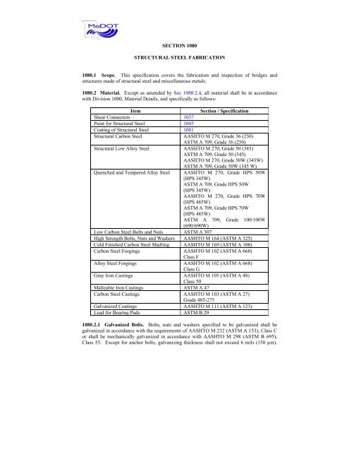
<strong>SECTION</strong> <strong>1080</strong><br />
<strong>STRUCTURAL</strong> <strong>STEEL</strong> <strong>FABRICATION</strong><br />
<strong>1080</strong>.1 Scope. This specification covers the fabrication and inspection of bridges and<br />
structures made of structural steel and miscellaneous metals.<br />
<strong>1080</strong>.2 Material. Except as amended by Sec <strong>1080</strong>.2.4, all material shall be in accordance<br />
with Division 1000, Material Details, and specifically as follows:<br />
Item Section / Specification<br />
Shear Connectors 1037<br />
Paint for Structural Steel 1045<br />
Coating of Structural Steel 1081<br />
Structural Carbon Steel AASHTO M 270, Grade 36 (250)<br />
ASTM A 709, Grade 36 (250)<br />
Structural Low Alloy Steel AASHTO M 270, Grade 50 (345)<br />
ASTM A 709, Grade 50 (345)<br />
AASHTO M 270, Grade 50W (345W)<br />
ASTM A 709, Grade 50W (345 W)<br />
Quenched and Tempered Alloy Steel AASHTO M 270, Grade HPS 50W<br />
(HPS 345W)<br />
ASTM A 709, Grade HPS 50W<br />
(HPS 345W)<br />
AASHTO M 270, Grade HPS 70W<br />
(HPS 485W)<br />
ASTM A 709, Grade HPS 70W<br />
(HPS 485W)<br />
ASTM A 709, Grade 100/100W<br />
(690/690W)<br />
Low Carbon Steel Bolts and Nuts ASTM A 307<br />
High Strength Bolts, Nuts and Washers AASHTO M 164 (ASTM A 325)<br />
Cold Finished Carbon Steel Shafting AASHTO M 169 (ASTM A 108)<br />
Carbon Steel Forgings AASHTO M 102 (ASTM A 668)<br />
Class F<br />
Alloy Steel Forgings AASHTO M 102 (ASTM A 668)<br />
Class G<br />
Gray Iron Castings AASHTO M 105 (ASTM A 48)<br />
Class 50<br />
Malleable Iron Castings ASTM A 47<br />
Carbon Steel Castings AASHTO M 103 (ASTM A 27)<br />
Grade 485-275<br />
Galvanized Coatings AASHTO M 111 (ASTM A 123)<br />
Lead for Bearing Pads ASTM B 29<br />
<strong>1080</strong>.2.1 Galvanized Bolts. Bolts, nuts and washers specified to be galvanized shall be<br />
galvanized in accordance with the requirements of AASHTO M 232 (ASTM A 153), Class C<br />
or shall be mechanically galvanized in accordance with AASHTO M 298 (ASTM B 695),<br />
Class 55. Except for anchor bolts, galvanizing thickness shall not exceed 6 mils (150 µm).
Fasteners installed prior to the completion of shop blast cleaning will not require galvanizing.<br />
The thickness of the zinc coating for galvanized bolts shall be measured on the wrench flats<br />
and top of the bolt head. For mechanically galvanized bolts, the significant surfaces as<br />
referenced in AASHTO M 298 (ASTM B 695) shall be the entire bolt surface, excluding the<br />
underside of the surface of the head and the shank surface between the threaded portion and<br />
the underside of the head. The thickness of the zinc coating on the galvanized nuts shall be<br />
measured on the wrench flats. For mechanically galvanized nuts, the significant surfaces shall<br />
be all surfaces of the nut excluding the threads. The thickness of the zinc coating on<br />
galvanized washers shall be measured on both sides. The significant surfaces on mechanically<br />
galvanized washers shall be all surfaces of the washer.<br />
<strong>1080</strong>.2.2 Fit Up Bolts. Fit up and shipping bolts shall be coated to prevent corrosion where a<br />
finish coat will not be applied. Shipping bolts for uncoated weathering steel will not require<br />
coating.<br />
<strong>1080</strong>.2.3 Falsework. Falsework material will be subject to the engineer's approval. All<br />
falsework material shall be in good condition such that the material performs as designed.<br />
Falsework piling shall be capable of withstanding driving to a depth sufficient to develop<br />
adequate bearing.<br />
<strong>1080</strong>.2.4 Certified Mill Test Reports. For structural steel, the contractor shall submit a copy<br />
of the certified mill test report giving the chemical analysis and results of physical tests on the<br />
material furnished. The mill test report shall state the location of the mill where the molten<br />
metal was produced. Two copies of the mill test report will be required for material used in<br />
railroad structures. If steel is produced outside the United States, the contractor shall submit a<br />
certified test report from a MoDOT approved U. S. laboratory showing specific results of<br />
chemical analysis and physical tests for each heat furnished and stating that the material meets<br />
the specification requirements. Mill tests and laboratory reports shall be submitted for<br />
approval before any request is made for shop or field inspection. In addition, the engineer<br />
may take samples for chemical analysis and physical tests from the fabricated steel delivered<br />
to the project site. Any time or cost effects caused by obtaining and analyzing samples from<br />
delivered steel shall be anticipated by the contractor as part of the quality assurance process<br />
and no compensation or additional time will be allowed for costs or delays associated with this<br />
activity. Unless otherwise specified, the supplementary requirements of AASHTO M 270<br />
(ASTM A 709) for Charpy V-notch impact tests in temperature zone 2 shall be mandatory<br />
where the contract documents indicate notch toughness is required for fracture critical or nonfracture<br />
critical components. Mill test reports shall include the results of Charpy V-notch<br />
testing and impact serial numbers for fracture critical components.<br />
<strong>1080</strong>.2.5 High Strength Fastener Assemblies. In addition to the requirements of Sec 712.2,<br />
high strength bolts, nuts and washers shall meet the following requirements. The contractor<br />
shall furnish a manufacturer's certification showing results of tests performed. Identification<br />
in accordance with the appropriate AASHTO/ASTM specifications shall be maintained by<br />
container markings which shall match identifying numbers on the certifications and be<br />
traceable to the certified mill test reports. High strength fastener assemblies shall be<br />
galvanized unless used with unpainted weathering steel or specifically indicated otherwise by<br />
the contract documents. When high strength bolts are used with weathering steel, the fasteners<br />
shall be Type 3. All certification testing requirements and mill test reports referenced in the<br />
following sections shall be in accordance with Sec 106.<br />
<strong>1080</strong>.2.5.1 Bolts. All bolts shall be in accordance with AASHTO M 164 (ASTM A 325). If<br />
the contractor elects to use load indicator bolts, only a hex head will be permitted. The type of<br />
head used shall be consistent throughout the entire structure, unless otherwise approved by the<br />
engineer.
<strong>1080</strong>.2.5.1.1 Proof Load Tests. Proof load tests in accordance with ASTM F 606 Method 1<br />
shall be performed. Minimum test frequency shall be in accordance with AASHTO M 164<br />
(ASTM A 325).<br />
<strong>1080</strong>.2.5.1.2 Wedge Tests. Wedge tests on full size bolts, in accordance with ASTM F 606,<br />
paragraph 3.5 shall be performed. If bolts are to be galvanized, tests shall be performed after<br />
galvanizing. Minimum test frequency shall be in accordance with AASHTO M 164<br />
(ASTM A 325).<br />
<strong>1080</strong>.2.5.2 Nuts. All nuts shall be in accordance with AASHTO M 292 (ASTM A 194) as<br />
applicable or AASHTO M 291 (ASTM A 563), except as follows.<br />
<strong>1080</strong>.2.5.2.1 Nut Grades. Ungalvanized nuts shall be grades 2, C, D or C3 with a minimum<br />
Rockwell hardness of 89 HRB or Brinell hardness 180 HB or heat treated grades 2H, DH or<br />
DH3. Nuts that are to be galvanized shall be heat treated grade 2H, DH or DH3.<br />
<strong>1080</strong>.2.5.2.2 Overtapping. Nuts to be galvanized shall be tapped oversize the minimum<br />
amount required for proper assembly. The amount of overtap in the nut shall be such that the<br />
nut will assemble freely on the bolt in the coated condition and shall be in accordance with the<br />
mechanical requirements AASHTO M 291 (ASTM A 563) and the rotational-capacity test.<br />
The overtapping requirements of ASTM A 563 will apply, except these limits shall be<br />
considered maximum values instead of the minimum, as currently shown.<br />
<strong>1080</strong>.2.5.2.3 Nut Lubrication. All galvanized nuts, including ASTM A 194 nuts, shall meet<br />
the supplementary requirements of ASTM A 563. Galvanized nuts shall be lubricated with a<br />
lubricant containing a dye of any color that contrasts with the color of the galvanizing.<br />
<strong>1080</strong>.2.5.2.4 Proof Load Tests. Proof load tests in accordance with ASTM F 606 shall be<br />
performed. Minimum test frequency shall be in accordance with AASHTO M 291<br />
(ASTM A 563) or AASHTO M 292 (ASTM A 194). If nuts are to be galvanized, tests shall<br />
be performed after lubricating.<br />
<strong>1080</strong>.2.5.2.5 Weathering Steel. When Type 3 fasteners are specified for use with weathering<br />
steel, nuts shall be in accordance with AASHTO M 291 (ASTM A 563) and shall be grades<br />
C3 or DH3.<br />
<strong>1080</strong>.2.5.3 Washers. All washers shall be in accordance with AASHTO M 293<br />
(ASTM F 436). Hardness testing shall be performed on galvanized washers. The coating<br />
shall be removed prior to taking hardness measurements.<br />
<strong>1080</strong>.2.5.4 Rotational-Capacity Tests. Rotational-capacity tests shall be performed on all<br />
bolt, nut and washer assemblies by the manufacturer or distributor prior to shipping. Washers<br />
shall be part of the test, regardless if they are required as part of the installation procedure or<br />
not. Tests shall be conducted after galvanizing when galvanizing is required.<br />
<strong>1080</strong>.2.5.4.1 Test Methods. Except as modified herein, the rotational-capacity test shall be<br />
performed in accordance with AASHTO M 164 (ASTM A 325).<br />
<strong>1080</strong>.2.5.4.2 Test Lots. Each combination of bolt production lot, nut lot and washer lot shall<br />
be tested as an assembly. Where washers are not required as part of the installation<br />
procedures, washers need not be included in the lot identification. A rotational-capacity lot<br />
number shall be assigned to each combination of lots tested. The minimum frequency of<br />
testing shall be two assemblies per rotational-capacity lot.
<strong>1080</strong>.2.5.4.3 Testing Device. The bolt, nut and washer assembly shall be assembled in a<br />
Skidmore-Wilhelm Calibrator or an acceptable equivalent device.<br />
<strong>1080</strong>.2.5.4.4 Minimum Rotation. The minimum rotation, from a snug tight condition, 10<br />
percent of the specified proof load, shall be as follows:<br />
Minimum Bolt Rotation<br />
Bolt Length Rotation<br />
≤ 4 Diameters 240° (2/3 turn)<br />
> 4 Diameters and ≤ 8 Diameters 360° (1 turn)<br />
> 8 Diameters 480° (1 1/3 turn)<br />
<strong>1080</strong>.2.5.4.5 Required Tension. The tension reached at the above rotation shall be equal to<br />
or greater than 1.15 times the required installation tension. The installation tension and the<br />
tension for the turn test for AASHTO M 164 (ASTM A 325) bolts shall be as follows:<br />
Required Bolt Tensions<br />
Diameter, in. 1/2 5/8 3/4 7/8 1.00 1-1/8 1-1/4 1-3/8 1-1/2<br />
(mm) (12.7) (15.9) (19.0) (22.2) (25.4) (28.6) (31.8) (34.9) (38.1)<br />
Req.<br />
Installation<br />
Tension, kips<br />
(kN)<br />
Turn<br />
Test Tension,<br />
kips (kN)<br />
<strong>1080</strong>.2.5.4.6 Torque. After the required installation tension has been exceeded, one reading<br />
of tension and torque shall be taken and recorded. The torque value shall be as follows:<br />
Where:<br />
12<br />
(53)<br />
14<br />
(62)<br />
19<br />
(85)<br />
22<br />
(98)<br />
28<br />
(125)<br />
32<br />
(142)<br />
39<br />
(173)<br />
45<br />
(200)<br />
Torque < 0.25 PD<br />
51<br />
(227)<br />
59<br />
(262)<br />
56<br />
(249)<br />
64<br />
(285)<br />
Torque = measured torque, foot-pounds (N-m)<br />
P = measured bolt tension, pounds (N)<br />
D = bolt diameter, feet (m)<br />
<strong>1080</strong>.2.5.4.7 Short Bolts. Bolts that are too short to test in a Skidmore-Wilhelm Calibrator<br />
may be tested in a steel joint. The maximum torque requirement shall be computed using a<br />
value of P equal to the turn test tension shown in Sec <strong>1080</strong>.2.5.4.5.<br />
<strong>1080</strong>.2.5.5 Reporting. The results of all tests, including zinc coating thickness, required<br />
herein and in the applicable AASHTO/ASTM specifications and the location and date of the<br />
tests performance, shall be recorded on the appropriate document. The tests need not be<br />
witnessed by an inspection agency. The manufacturer or distributor performing the tests shall<br />
certify the results are accurate.<br />
<strong>1080</strong>.2.5.6 Documentation for High Strength Fastener Assemblies.<br />
71<br />
(316)<br />
82<br />
(365)<br />
85<br />
(378)<br />
98<br />
(436)<br />
103<br />
(458)<br />
118<br />
(525)<br />
<strong>1080</strong>.2.5.6.1 Mill Test Reports. A Mill Test Report (MTR) shall be furnished for all mill<br />
steel used in the manufacture of the bolts, nuts or washers. The MTR shall indicate the<br />
location where the material was melted and manufactured.
<strong>1080</strong>.2.5.6.2 Manufacturer Certified Test Reports. The manufacturer of the bolts, nuts and<br />
washers shall furnish a Manufacturer Certified Test Report (MCTR) for each item furnished<br />
including the following information:<br />
(a) The lot number of each of the items tested.<br />
(b) The rotational-capacity lot number as required in Sec <strong>1080</strong>.2.5.4.2.<br />
(c) The results of the tests required in Sec <strong>1080</strong>.2.5.5.<br />
(d) The pertinent information required in Sec <strong>1080</strong>.2.5.4.2.<br />
(e) A statement that MCTR for the items are in conformance to this<br />
specification and the applicable AASHTO/ASTM specifications.<br />
The location where the bolt assembly components were manufactured.<br />
Rotational capacity testing if completed by the manufacturer.<br />
<strong>1080</strong>.2.5.6.3 Distributor Certified Test Reports. The Distributor Certified Test Report<br />
(DCTR) shall include MCTR for the various bolt assembly components. The rotationalcapacity<br />
test may be performed by a distributor in lieu of a manufacturer and shall be reported<br />
on the DCTR. The DCTR shall indicate the following if not included in the MCTR:<br />
(a) The results of the tests required in Sec <strong>1080</strong>.2.5.5.<br />
(b) The pertinent information required in Sec <strong>1080</strong>.2.5.4.2.<br />
(c) The rotational-capacity lot number as required in Sec <strong>1080</strong>.2.5.4.3.<br />
(d) A statement that the MCTR are in accordance with this specification and<br />
the applicable AASHTO/ASTM specifications.<br />
(e) Certification of galvanizing from the galvanizing supplier shall be in<br />
accordance with Sec <strong>1080</strong>.2.1.<br />
<strong>1080</strong>.2.5.7 Shipping of High Strength Fastener Assemblies. Bolts, nuts and washers,<br />
where required, from each rotational-capacity lot shall be shipped in the same container in<br />
proportionate quantities for use. If there is only one production lot number for each size of nut<br />
and washer, the nuts and washers may be shipped in separate containers. Each shipping<br />
container shall be permanently marked by the manufacturer or distributor with the rotationalcapacity<br />
lot number such that identification will be possible at any stage prior to installation.<br />
The appropriate MTR, MCTR or DCTR shall be supplied in accordance with the contract<br />
documents.<br />
<strong>1080</strong>.2.6 Machine Bolts. Machine bolted field connections shall be made with machine bolts<br />
having American Standard Regular Heads and Nuts of hexagonal shape and shall be in<br />
accordance with ANSI B 18.2.1 and B 18.2.2. Threads shall extend slightly beyond the nut to<br />
permit burring. One plain washer in accordance with ANSI B 18.22.1 shall be used at all<br />
slotted holes.<br />
<strong>1080</strong>.2.7 Cast Steel. For cast steel, the foundry shall furnish a certified copy of foundry<br />
reports giving the chemical analysis and results of physical tests on the material from each<br />
heat. These reports shall be submitted for approval of material being furnished before any<br />
required machine work is done on the castings.
<strong>1080</strong>.2.8 Cast Iron. For gray iron castings, the foundry shall furnish one finished tension test<br />
specimen in accordance with AASHTO M 105 (ASTM A 48) from each heat. The required<br />
machine work shall not proceed until material being furnished has been approved. If cast steel<br />
is furnished in lieu of gray iron, the minimum tensile strength shall be 50,000 psi (345 MPa).<br />
<strong>1080</strong>.2.9 Identification of Metals. The steel shall be stamped or stenciled and color striped<br />
with paint at the mill. Heat numbers shall be steel stamped or stenciled with paint at the mill.<br />
Separate markings and color codes shall be in accordance with AASHTO M 160 (ASTM A 6).<br />
The characteristic color stripes shall be placed on each part cut from the mill piece. For steels<br />
not covered by AASHTO M 160 (ASTM A 6), the fabricator shall furnish the engineer the<br />
color coding in writing before fabrication begins. Heat numbers shall be painted on all<br />
principal pieces and these pieces shall be so noted on the shop drawings. Principal pieces for<br />
this requirement shall include all beams, flanges, webs, splice plates, cover plates, bearings,<br />
bearing stiffener plates, load bearing members of end diaphragms, pin plates, hanger plates<br />
and others as may be directed by the engineer. Principal pieces shall include individual plates<br />
of all truss members, truss gusset plates, splice plates and floorbeam connection angles. The<br />
color code and heat number markings shall be placed on the material such that the markings<br />
are visible throughout the work of fabrication. Loss of identification on pieces or items will<br />
be cause for rejection of the pieces or items.<br />
<strong>1080</strong>.2.9.1 Fracture Critical Members. Principal pieces requiring identification shall also<br />
include components of fracture critical members. Traceability of both heat numbers and<br />
impact serial numbers shall be maintained for fracture critical members and attachments.<br />
<strong>1080</strong>.2.9.2 Direction of Rolling. Unless otherwise indicated in the contract documents, steel<br />
plates for main members and splice plates for flanges and main tension members shall be cut<br />
and fabricated such that the primary direction of rolling is parallel to the direction of the<br />
principal tensile or compressive stresses. The direction of rolling shall be maintained for all<br />
principal pieces during fabrication.<br />
<strong>1080</strong>.2.10 Steel Stamping. Any metal die stamping of match marks and erection marks in<br />
structural steel members shall be limited to a position in the end 1 1/2 inches (38 mm) of<br />
flange plates and flange splice plates, the middle third of web plates and the outside edge of<br />
the middle third of web splice plates. Metal die stamping at other locations or for other<br />
purposes may be approved by the engineer provided low stress dies are used. Low stress dies<br />
will be defined as those manufactured to produce impressions that are rounded at the bottom<br />
rather than sharp edged. Metal die stamping on pin plates and hanger plates will not be<br />
permitted.<br />
<strong>1080</strong>.3 Fabrication and Inspection.<br />
<strong>1080</strong>.3.1 Quality Assurance Inspection. The engineer will be responsible for QA inspection<br />
to assure the quality of the fabricated material. QA inspection by the engineer will not relieve<br />
the contractor of the responsibility to provide fabricated structural steel items in accordance<br />
with the contract documents. Sufficient QC, as necessary to assure work being performed<br />
conforms to the contract documents, shall be the responsibility of the contractor and<br />
fabricator. Following adequate notification that QC inspections and testing by the fabricator<br />
have been performed, QA inspection will be at the option of the engineer. Regardless of the<br />
location and degree of QA inspection, material and workmanship not meeting specified<br />
performance criteria or conforming to the contract documents or recognized good practice<br />
may be rejected at any time prior to final acceptance of the work.<br />
<strong>1080</strong>.3.1.1 Locations of Inspection. QA inspection of fabricated material will ordinarily be<br />
made in the shop for fabricating shops within the 48 contiguous States and for shops outside
the U. S., but within 1000 miles (1600 km) of Jefferson City, MO. High strength bolts, nuts<br />
and washers shall be presented for sampling at the fabrication shop performing the primary<br />
fabrication or at a location agreed to by Construction and Materials. In some cases, QA<br />
inspection in the fabrication shop may be waived and inspection made when the fabricated<br />
material is delivered to the project site. All costs of QA inspection at fabricating shops located<br />
both outside the 48 contiguous States and more than 1000 miles (1600 km) from Jefferson<br />
City, shall be at the contractor’s expense. In such cases, the contractor will be charged with<br />
transportation costs and expenses of QA inspectors for trips made from Jefferson City to<br />
locations to which the inspectors must travel for shop inspection work. These transportation<br />
costs and expenses of QA inspectors will be deducted by the Commission from monies due<br />
the contractor.<br />
<strong>1080</strong>.3.1.2 Notification of Inspection. The engineer shall be notified at least four working<br />
days prior to the beginning of the shop fabrication so a QA inspector may be present if so<br />
desired and to allow the QA inspector to make travel arrangements. If the fabricator notifies<br />
and requests inspection and the QA inspector arrives at the location of inspection to find the<br />
material is not ready for inspection as indicated in the request, any travel costs incurred by<br />
MoDOT for additional inspection shall be paid by the contractor.<br />
<strong>1080</strong>.3.1.3 Access for Inspection. The engineer shall have full access to all parts of the shop<br />
or project site where material is being fabricated or assembled and shall be provided with<br />
every reasonable facility for determining the character of material and workmanship.<br />
<strong>1080</strong>.3.1.4 Field Inspection. No increased time or compensation will be allowed for<br />
additional work, delays or additional costs as a result of QA inspection at the project site,<br />
including required repairs, including where samples were removed, refabrication, securing<br />
samples for chemical analysis and physical tests.<br />
<strong>1080</strong>.3.1.5 Office Space. A suitable office area shall be provided for exclusive use by the<br />
engineer. The office may be enclosed or semi-enclosed as available at the location of QA<br />
inspection, but shall be suitable for use as determined by the engineer. The floor space shall<br />
be at least 120 square feet (11 m 2 ) unless otherwise approved by the engineer, weatherproof,<br />
secure, insulated and lighted. The office space shall be adequately ventilated, heated and air<br />
conditioned. Electric outlets with 110-120 volt, 60 Hz current and a telephone with outside<br />
line, inter-plant and dial-up computer capabilities shall be provided. Office furniture<br />
consisting of a desk, a minimum of 30 x 60 inches (750 x 1500 mm) with drawers, a swivel<br />
desk chair with arms and a storage/filing cabinet with lock hardware and key shall be<br />
provided. All office furniture will be subject to approval by the engineer. Should any<br />
furniture become unsatisfactory, the furniture shall be promptly repaired or replaced to the<br />
satisfaction of the engineer. Accessible parking shall be provided near the office any time the<br />
shop is in operation on MoDOT projects. No direct payment will be made for furnishing and<br />
maintaining an acceptable office area for QA inspection.<br />
<strong>1080</strong>.3.1.6 Certifications. All structural steel fabricators performing work for the following<br />
listed components of steel structures shall be certified prior to the start of fabrication under the<br />
appropriate category of the AISC Quality Certification Program as follows:<br />
(a) Fabricators of main load-carrying components of welded plate girders, box<br />
girders, trusses and arches shall be certified under the AISC Major Steel Bridges category<br />
(Cbr). Fabricators of fracture critical members shall be certified under this category, with the<br />
additional endorsement for fracture critical capability.<br />
(b) Fabricators of main load-carrying components for simple span or<br />
continuous rolled beam bridges and POT bearings shall, as a minimum, be certified under the<br />
AISC Simple Steel Bridge Structures category (Sbr).
(c) Fabricators of overhead sign trusses, temporary bridges and steel bearings<br />
shall, as a minimum, be certified under the AISC Conventional Steel Buildings category<br />
(Sbd).<br />
(d) AISC certification will not be required for manufacturers of simple<br />
laminated or elastomeric bearing assemblies.<br />
<strong>1080</strong>.3.2 Shop Drawings. Shop drawings for structural steel and miscellaneous metals shall<br />
be required and shall be prepared in strict accordance with the design details shown on the<br />
plans. If details are lacking, the details shall be supplied and shall conform to the design plans<br />
and specifications. All drawings shall be clear and complete and shall be thoroughly checked<br />
before submittal. Shop drawings shall be completely titled in accordance with the contract<br />
plans and shall pertain to only a single structure. Four sets of the shop drawings for railroad<br />
structures and two sets for other structures shall be submitted to Bridge for approval. The<br />
prints submitted shall be legible and shall have distinct details of sufficient contrast to be<br />
suitable for microfilming. Prints that do not have the desired clarity and contrast will be<br />
returned for corrective action. One set of prints will be returned marked reviewed or approved<br />
subject to noted corrections. The contractor shall promptly make necessary corrections and<br />
resubmit for final approval. When shop drawings are approved, the contractor shall furnish as<br />
many additional prints as requested. Reproductions on cloth or film of the original shop<br />
drawings shall be required for railroad structures and shall be delivered to the engineer prior to<br />
completion of the work. The approval of shop drawings will cover only the general design<br />
features and in no case shall this approval be considered to cover errors or omissions in shop<br />
details. The contractor shall be responsible for the accuracy of the shop drawings, the<br />
fabrication of material and the fit of all connections. All changes in the fabrication and<br />
erection work caused by errors in shop drawings and any changes in fabrication necessary for<br />
satisfactory results shall be at the contractor’s expense. After shop drawings have been<br />
approved, no changes in dimensions or substitutions of sections shall be made without written<br />
approval from the engineer. Shop drawings shall be revised to show any authorized changes<br />
and the required number of prints shall be furnished to the engineer.<br />
<strong>1080</strong>.3.2.1 Non-Domestic Shop Drawings. Shop drawings from fabricators located outside<br />
the 48 contiguous States, whether marked approved or approved subject to the corrections<br />
noted, will be returned to the contractor and the contractor shall be responsible for transmitting<br />
the drawings to the fabricator for further handling. Should such fabricator also be the<br />
contractor, all prints will be returned to the office located on the project.<br />
<strong>1080</strong>.3.2.2 Weld Procedures. All welding procedures to be used shall be prepared by the<br />
manufacturer, contractor or fabricator as a written procedure specification. For new welding<br />
procedures, two copies shall be submitted for approval prior to submitting shop drawings.<br />
Approved weld procedures will be kept on file by Bridge and may be considered for use on<br />
multiple projects. Any changes to the parameters of an approved welding procedure shall<br />
require submittal for approval. The shop drawings submitted for approval shall indicate the<br />
welding procedure to be used for each joint.<br />
<strong>1080</strong>.3.2.3 Verification of Work. By submission of shop drawings, the contractor represents<br />
to the Commission that all material, field measurements, construction requirements,<br />
performance criteria and similar data have been verified. The contractor further represents<br />
that the shop drawings have been coordinated and verified with the details of the work to be<br />
performed by other fabricators and entities on the project. No allowance for additional costs<br />
or delays will be made to the contractor for incorrect fabrication as a result of failure to<br />
coordinate or perform these verifications.
<strong>1080</strong>.3.3 Fabrication. Fabrication of all parts of the structure shall be carefully done in strict<br />
accordance with the approved shop drawings.<br />
<strong>1080</strong>.3.3.1 Straightening. Straightening of any deformed structural material shall be<br />
performed by non-injurious methods prior to being worked in the shop. Sharp kinks and<br />
bends will be cause for rejection.<br />
<strong>1080</strong>.3.3.2 Holes. Holes for connections of main members shall be subpunched or subdrilled<br />
and reamed while assembled in the shop or may be drilled from the solid with main members<br />
and each splice plate fully assembled in their final erected positions. Holes for floor beams<br />
and framed stringer connections shall be drilled or reamed to a steel template of sufficient<br />
thickness to center the drill accurately and all members to be secured through the same group<br />
of holes shall be drilled or reamed from the same template. Holes may be punched full size in<br />
secondary members such as lateral, longitudinal and sway bracing, lacing bars, stay plates and<br />
diaphragms. Stacking of web splice plates during drilling or reaming operations on straight<br />
girders will be permitted.<br />
<strong>1080</strong>.3.3.3 Reaming and Finishing of Holes. Reaming or drilling full size from the solid<br />
shall be done while the truss, girder, continuous I-beam or other component as noted, is<br />
assembled, either in an upright position or on its side, properly adjusted for camber and sweep<br />
and after the connecting parts have been firmly fastened together. A minimum of one full<br />
span, from bearing to bearing, shall be fully assembled before reaming or drilling full size<br />
begins. Connecting parts assembled in the shop for the purpose of reaming or drilling holes<br />
for field or shop connections shall not be interchanged or reversed and shall be matchmarked.<br />
A diagram showing such marks shall be detailed on the shop drawings. Burrs resulting from<br />
reaming, drilling or punching shall be removed. All connections shall be disassembled after<br />
drilling or reaming to make these holes accessible for deburring. Required cleaning and<br />
painting shall be done after disassembly. Reamed, drilled or punched holes shall be round and<br />
perpendicular to the member. Any hole out of round more than 1/16 inch (1.5 mm) will be<br />
cause for rejection of the plate. Eighty-five percent of the holes in any group shall not show<br />
an offset greater than 1/32 inch (1 mm) between adjacent thicknesses of metal after reaming or<br />
drilling. All holes shall be drilled or reamed and aligned such that a bolt of the specified<br />
diameter will enter the hole and the head and nut will seat on the metal before tensioning.<br />
<strong>1080</strong>.3.3.4 Applicable Codes. All welding, oxygen cutting, shearing and clipping and<br />
dimensional tolerances shall be in accordance with the ANSI/AASHTO/AWS D1.5: 2002,<br />
Bridge Welding Code. Tubular steel structures shall be governed by the current edition of the<br />
AWS D1.1, Structural Welding Code - Steel, in effect at the time of the contract, unless<br />
specified otherwise. Aluminum structures shall be governed by the current edition of the<br />
AWS D1.2, Structural Welding Code - Aluminum, except as amended by Sec 903, unless<br />
otherwise indicated.<br />
<strong>1080</strong>.3.3.5 Modifications to the Bridge Welding Code. The following modifications to the<br />
ANSI/AASHTO/AWS D1.5 2002, Bridge Welding Code (AWS), shall apply:<br />
<strong>1080</strong>.3.3.5.1 AWS Sec 1.3 Paragraph 1.3.4 - Paragraph 1.3.4 shall be replaced with the<br />
following:<br />
The gas metal arc welding process shall not be used on any structural components of bridges.<br />
Approved gas metal arc processes may be used for incidental, non-structural components as<br />
may be specifically approved by the engineer. Tack welding with an approved gas metal arc<br />
process will be permitted for joints that will subsequently be welded using an approved<br />
submerged arc automatic welding process.
<strong>1080</strong>.3.3.5.2 AWS Sec 1.3 Paragraph 1.3.7 - A new Paragraph 1.3.7 shall be added as<br />
follows:<br />
All primary shop welds shall be made by approved submerged arc automatic welding<br />
processes. The automatic welding process shall be one in which the wire or electrode feed,<br />
speed of travel and guidance are all mechanically controlled. Noncompliance with this<br />
requirement will be cause for rejection of the welded material unless prior approval is granted<br />
by the engineer for welding the specified joints by the use of other processes. The automatic<br />
welding process requirement for primary shop welds shall be shown on the shop drawings for<br />
each joint. Primary shop welds will be defined as flange and web butt welded splices in<br />
I-beams, box members and plate girders, plate girder or box flange to web fillet welds and<br />
cover plate to flange fillet welds.<br />
<strong>1080</strong>.3.3.5.3 AWS Sec 2.8 Paragraph 2.8.1.1 - Paragraph 2.8.1.1 shall be replaced with the<br />
following:<br />
The minimum fillet weld size, except for fillet welds used to reinforce groove welds, shall be<br />
as shown in the following table or as calculated using procedures established to prevent<br />
cracking in accordance with Paragraph 4.2.2. In both cases, the minimum size will apply if<br />
the size is sufficient to satisfy design requirements.<br />
Material Thickness of Thicker Part Joined, Minimum Size of Fillet Weld<br />
in. (mm)<br />
a , in.<br />
(mm)<br />
To 3/4 (20) 1/4 (6) b<br />
Over 3/4 (20) to 2 1/2 (64) 5/16 (8) b<br />
Over 2 1/2 (64) 1/2 (14)<br />
a<br />
Except that the weld size need not exceed the thickness of the thinner part joined.<br />
b<br />
Single pass welds must be used.<br />
<strong>1080</strong>.3.3.5.4. AWS Sec 3.2 Paragraph 3.2.2.2 (4) - A new Paragraph 3.2.2.2 (4) shall be<br />
added as follows:<br />
Quenched and tempered steel plate may be thermally cut provided sufficient preheating is<br />
applied according to the steel producer's written recommendations. Procedures for thermal<br />
cutting of quenched and tempered steel plate, along with the steel producer's written report,<br />
shall be submitted to the engineer for approval prior to the start of such work.<br />
<strong>1080</strong>.3.3.5.5 AWS Sec 3.2 Paragraph 3.2.3.4 - Paragraph 3.2.3.4 shall be replaced with the<br />
following:<br />
The corrective procedures described in Table 3.1 shall not apply to discontinuities in rolled<br />
base-metal surfaces. Such discontinuities may be corrected by the fabricator in accordance<br />
with ASTM A 6 (AASHTO M 160), except that repair by welding will be permitted only<br />
when approved by the engineer. Approval will be limited to areas where there will be less<br />
than the maximum design stress in the finished structure. When surface imperfections in<br />
alloy, low alloy and carbon steel plates are repaired by grinding, the surfaces shall have edges<br />
faired to the plate surface with a maximum slope of 1 in 10.<br />
<strong>1080</strong>.3.3.5.6 AWS Sec 3.2 Paragraph 3.2.11 - A new paragraph 3.2.11 shall be added as<br />
follows:<br />
Sheared edges of plates not to be welded that are more than 5/8 inch (16 mm) thick and<br />
carrying calculated stress shall be planed to a depth of 1/4 inch (6 mm).<br />
<strong>1080</strong>.3.3.5.7 AWS Sec 3.3.8 - Sec 3.3.8 shall be replaced with the following:
Temporary welds shall be subject to the same WPS requirements as final welds. Temporary<br />
welds shall be removed unless otherwise permitted by the engineer and the surface shall be<br />
made flush with the original surface. Unless previously approved in writing by the engineer,<br />
there shall be no temporary welds for fabrication, transportation, erection or other purposes on<br />
main members except at locations more than 1/6 the depth of the web from the flanges of<br />
beams and girders. There shall be no temporary welds in tension zones of members of<br />
quenched and tempered steels. Temporary welds at other locations shall be shown on shop<br />
drawings and shall be made with approved consumables. Removal of temporary welds shall<br />
conform to Paragraphs 3.3.7.3 and 3.3.7.4.<br />
<strong>1080</strong>.3.3.5.8 AWS Sec 3.4 Paragraph 3.4.6 - Paragraph 3.4.6 shall be replaced with the<br />
following:<br />
All shop splices in each component part of a cover-plated beam or built-up member shall be<br />
made and all required nondestructive testing completed and approved by the engineer before<br />
the component part is welded to other component parts of the member. Long members or<br />
member sections may be made by shop-splicing subsections, each made in accordance with<br />
this subsection (See 2.17.6). All shop splices shall be made using full penetration welds that<br />
fully develop the capacity of the original member. Additional shop splices required due to<br />
length limits of available material may be used if detailed on the shop drawings and placed at<br />
locations approved by the engineer. No additional payment will be made for any additional<br />
shop splices placed in the members at the option of the contractor, including shop splices that<br />
may be required as a result of material limitations.<br />
<strong>1080</strong>.3.3.5.9 AWS Sec 3.5 Paragraph 3.5.1.8.1 - A new Paragraph 3.5.1.8.1 shall be added<br />
as follows:<br />
The maximum permissible variation from specified width for rolled or burned flange plates<br />
shall be -1/8 inch to +3/8 inch (-3 mm to +9.5 mm).<br />
<strong>1080</strong>.3.3.5.10 AWS Sec 3.5 Paragraph 3.5.1.9 - Paragraph 3.5.1.9 shall be replaced with the<br />
following:<br />
The bearing ends of bearing stiffeners shall be flush and square with the web and shall have at<br />
least 75 percent of this area in contact with the inner surface of the flanges. The remaining 25<br />
percent of the area of the bearing stiffener shall be within 0.010 inch (0.25 mm) of the inner<br />
surface of the flanges. When bearing against a steel base or seat, all steel components shall fit<br />
within 0.010 inch (0.25 mm) for 75 percent of the projected area of web and stiffeners and not<br />
more than 1/32 inch (0.8 mm) for the remaining 25 percent of the projected area. Girders<br />
without stiffeners shall bear on the projected area of the web on the outer flange surface within<br />
0.010 inch (0.25 mm). The included angle between web and flange shall not exceed 90<br />
degrees in the bearing length. The top surface of a flange or shelf plate supporting a steel<br />
bearing rocker shall be considered a flat surface with a tolerance of 0.003 inch per inch<br />
(0.003 mm/mm) in any direction over the projected area of the rocker. The top surface of a<br />
flange or shelf plate in direct contact with elastomeric bearings shall not deviate from a true<br />
plane surface by more than 1/16 inch (1.5 mm).<br />
<strong>1080</strong>.3.3.5.11 AWS Sec 3.5 Paragraph 3.5.1.16 - A new Paragraph 3.5.1.16 shall be added<br />
as follows:<br />
Permissible variation in length of assembled beams or girders between the centerline of<br />
bearing devices shall not exceed plus or minus 1/4 inch (6 mm) for any one span or plus or<br />
minus 1/2 inch (12.7 mm) for any two or more spans within the assembled unit. The actual<br />
centerline of any bearing device shall lie within the thickness of the bearing stiffener.
<strong>1080</strong>.3.3.5.12 AWS Sec 3.7 Paragraph 3.7.2.5 - A new Paragraph 3.7.2.5 shall be added as<br />
follows:<br />
If, after three repairs to the same area of a weld requiring radiographic quality, there is any<br />
part of the original defect remaining or there is a new rejectable indication, the total joint shall<br />
be cut apart, all deposited weld metal removed, joint preparation made and the total joint<br />
rewelded.<br />
<strong>1080</strong>.3.3.5.13 AWS Sec 3.7 Paragraph 3.7.2.6 - A new Paragraph 3.7.2.6 shall be added as<br />
follows:<br />
The gas metal arc welding process shall not be used for the repair of welds except when<br />
repairing welds made with the GMAW process.<br />
<strong>1080</strong>.3.3.5.14 AWS Sec 5.21 Paragraph 5.21.6.2 - A new Paragraph 5.21.6.2 shall be added<br />
as follows:<br />
Any cost involved in qualifying welders, welding operators and tackers, including all material<br />
costs, finishing of test specimens, the physical testing of finished specimens and any<br />
radiography required shall be borne by the contractor. Required radiography and physical<br />
testing of finished specimens shall be performed at test facilities approved by the engineer.<br />
<strong>1080</strong>.3.3.5.15 AWS Sec 6.6 Paragraph 6.6.5 - Paragraph 6.6.5 shall be replaced with the<br />
following:<br />
If the engineer subsequently requests nondestructive testing, not specified in the original<br />
contract agreement, the contractor shall perform any requested testing or shall permit any<br />
requested testing to be performed. Handling, surface preparation, repair welds and any<br />
nondestructive testing requested by the engineer, as a result of weld repair, shall be at the<br />
contractor’s expense. Payment for any non-destructive testing that does not indicate the need<br />
for repair to the tested weld will be in accordance with Sec 109.4.<br />
<strong>1080</strong>.3.3.5.16 AWS Sec 6.7 Paragraphs 6.7.1, 6.7.1.1 and 6.7.1.2 - Paragraphs 6.7.1, 6.7.1.1<br />
and 6.7.1.2 shall be replaced with the following:<br />
Radiographic inspection shall be required for areas of both shop and field butt welds as<br />
specified herein. One hundred percent inspection shall be required for flanges of rolled beams<br />
and girders and 100 percent of transverse butt welds in webs for a distance of no less than onesixth<br />
of the web depth from each flange and 25 percent of the remainder of the web depth. At<br />
least one-third of the length of all longitudinal web splices shall be radiographed at even<br />
intervals throughout the length of the splice. When a rejectable defect is found by radiography<br />
in any partially tested joint, either initially or in a later additional radiograph, tests shall be<br />
conducted on either side of and adjacent to the rejectable test area. If a rejectable defect is<br />
found in any additional areas, then 100 percent of vertical web splices and an additional 10<br />
percent of total weld length in longitudinal web splices shall be tested. The location of these<br />
additional test areas shall be as directed by the engineer. All complete joint penetration<br />
groove welds in T- and corner joints shall be tested by ultrasonic testing.<br />
<strong>1080</strong>.3.3.5.17 AWS Sec 6.10 Paragraph 6.10.3.4 - A new Paragraph 6.10.3.4 shall be added<br />
as follows:<br />
Edge blocks shall be used when radiographing butt welds greater than 1/2 inch (13 mm) in<br />
thickness. The edge blocks shall have a length sufficient to extend beyond each side of the<br />
weld centerline for a minimum distance of 2 inches (50 mm) and shall have a thickness equal
to the thickness of the weld, plus or minus 1/16 inch (1.5 mm). The minimum width of the<br />
edge blocks shall be no less than 1 inch (25 mm). The edge blocks shall be centered on the<br />
weld with a snug fit against the plate being radiographed, allowing no more than 1/16 inch<br />
(1.5 mm) gap. Edge blocks shall be made of radiographically clean steel and the surface shall<br />
have a finish of ANSI 125µin. (3µm) or smoother (refer to ANSI/AWS D1.1-98 Structural<br />
Welding Code - Steel, Sec 6.17, Paragraph 6.17.13 and Figure 6.15).<br />
<strong>1080</strong>.3.3.5.18 AWS Sec 6.10 Paragraph 6.10.11.2 - Paragraph 6.10.11.2 shall be replaced<br />
with the following:<br />
If the greatest and least thickness of a weld connecting parts of different thickness cannot be<br />
rendered with adequate contrast on a single film with a single exposure, a dual film or dual<br />
exposure technique shall be used to obtain suitable density for both the greatest and the least<br />
thickness of the weld.<br />
<strong>1080</strong>.3.3.5.19 AWS Sec 6.12 Paragraph 6.12.4 - A new Paragraph 6.12.4 shall be added as<br />
follows:<br />
After completion of all radiographic inspection, the contractor shall submit to the engineer one<br />
set of drawing details showing the location and identification numbers of all radiographs<br />
taken.<br />
<strong>1080</strong>.3.3.5.20 AWS Sec 6.26 Paragraph 6.26.2.1 - Paragraph 6.26.2.1 shall be replaced with<br />
the following:<br />
For any welds, the greatest dimension of any porosity or fusion type discontinuity that is 1/16<br />
inch (1.5 mm) or larger in greatest dimension shall not exceed the size, B, indicated in Figure<br />
6.8 for the effective throat or weld size involved. The distance from any porosity or fusion<br />
type discontinuity described above to another such discontinuity, to an edge or to the toe or<br />
root of any intersecting flange-to-web weld shall not be less than the minimum clearance<br />
allowed, C, indicated in Figure 6.8 for the size of discontinuity under examination.<br />
<strong>1080</strong>.3.3.5.21 AWS Sec 6.26 Paragraph 6.26.2.2 and Figure 6.9 - Delete paragraph 6.26.2.2<br />
and Figure 6.9.<br />
<strong>1080</strong>.3.3.5.22 AWS Sec 6.26 Paragraph 6.26.3.1 - Paragraph 6.26.3.1 shall be replaced with<br />
the following:<br />
Welds subjected to ultrasonic testing in addition to visual inspection shall conform to the<br />
requirements of Table 6.3.<br />
<strong>1080</strong>.3.3.6 Calibrated Tapes. When the contract involves fabrication of a bridge with a<br />
bearing-to-bearing span of 100 feet (30 m) or more, certifications and identifying numbers of<br />
calibrated measuring tapes or numbered tapes matched to a calibrated master shall be kept on<br />
file for review by the engineer. Certification of the measuring tape to be used or certification<br />
of the master from which the tape was matched shall be traceable to the U. S. National Bureau<br />
of Standards. Certification of tapes for shop use shall be renewed at least every two years.<br />
<strong>1080</strong>.3.3.7 Connection Angles. Connection angles for floor beams and stringers shall be<br />
flush and shall be correct as to position and length of member. If milling is required, no more<br />
than 1/16 inch (1.5 mm) shall be removed from the thickness of the angles.<br />
<strong>1080</strong>.3.3.8 Longitudinal Stiffeners. Longitudinal girder web stiffeners shall be a single<br />
length if possible. If more than a single length is necessary, such lengths shall be joined by a<br />
full penetration butt weld. The location of these butt welds shall be shown on the shop
drawings for each joint and shall be subject to approval by the engineer. Runoff plates in<br />
accordance with AWS Section 3.12 shall be used. The welds shall be radiographically tested<br />
and accepted in accordance with AWS Sec 6.10 prior to being attached to the web.<br />
<strong>1080</strong>.3.3.9 Pins. Pins shall be furnished true to size and shall be straight, smooth and free<br />
from flaws. Pins shall be provided with hexagonal chamfered nuts. The screw ends shall be<br />
sufficiently long to permit burring the threads when members are connected. Pilot and driving<br />
nuts shall be furnished for each size of pins where required. Threads for all pins and bolts<br />
shall conform with the ANSI B1.1 Free Fit - Class 2 Series except that when recessed nuts are<br />
specified, pin ends requiring a threaded diameter of 1 3/8 inches (35 mm) or more shall have<br />
six threads per inch (25 mm). If standard nuts are specified for this size pin, a minimum of<br />
four threads to the inch (25 mm) shall be used.<br />
<strong>1080</strong>.3.3.10 Pin Holes. Pin holes shall be bored true to size, smooth and straight, at right<br />
angles to the axis of the member and parallel with each other. The boring shall be done after<br />
the member is assembled and welded. The center-to-center distance of pin holes shall be<br />
correct within 1/32 inch (0.8 mm) for an individual component or member. The diameter of<br />
pin holes shall not exceed that of the pin by more than 1/50 inch (0.5 mm) for pins 4 inches<br />
(100 mm) or less in diameter or no more than 1/32 inch (0.8 mm) for pins larger than 4 inches<br />
(100 mm) in diameter.<br />
<strong>1080</strong>.3.3.11 Casting. Castings shall be free from inclusions of foreign material, casting<br />
faults, injurious blow holes or other defects which render the castings unsuitable for the<br />
service intended. Castings shall be properly filleted at re-entrant angles. No tolerance will be<br />
allowed below the dimensions shown on the plans for thicknesses over an appreciable area of<br />
the casting. A reasonable oversize will not be cause for rejection.<br />
<strong>1080</strong>.3.3.12 Bent Plates. Bent plates shall be cold bent and taken from the stock plates such<br />
that the bend line will be at right angles to the direction of rolling. The radius of bends,<br />
measured to the concave face of the metal, shall be in accordance with the requirements as<br />
shown in the table below, in which "T" is the thickness of the plate. If a shorter radius is<br />
required, the plates shall be hot bent. Hot bent plates shall be bent at right angles to the<br />
direction of rolling. Before hot or cold bending, the corners of the plate shall be rounded to a<br />
radius of 1/16 inch (1.5 mm) throughout that portion of the plate at which the bending is to<br />
occur.<br />
Angle Through Which Plate is Bent Minimum Radius<br />
61 degrees to 90 degrees 1.0 T<br />
Over 90 degrees to 120 degrees 1.5 T<br />
Over 120 degrees to 150 degrees 2.0 T<br />
<strong>1080</strong>.3.3.13 Surface Finish. Bearing plates of rolled steel not requiring a surface finish shall<br />
be straightened to a plane surface. The surfaces of plates of rolled steel or cast material which<br />
are to be in contact shall be finished as shown on the plans and the final finish shall be<br />
prepared in a manner to give at least 50 percent contact as indicated by standard machinist's<br />
blue test. Rockers and pedestals made from rolled steel shall be finished after welding. If a<br />
flat surface is shown on the plans, the tolerance shall be 0.003 inch per inch (0.003 mm/mm)<br />
in any direction. Flat surfaces in full contact shall be finished at right angles to each other.<br />
Bearing plates shall be assembled in sets. The surface finish of bearing and base plates and<br />
other bearing surfaces that are to come in contact with each other or with concrete shall meet<br />
the following surface roughness requirements as defined in ANSI B 46.1, Surface Roughness,<br />
Waviness and Lay, Part I:
Surface Roughness Requirements Micro-inches (µm), Max.<br />
Steel Slabs 2000 (51)<br />
Heavy Plates in Contact in Shoes to be Welded 1000 (25)<br />
Milled Ends of Compression Members, 500 (12)<br />
Stiffeners and Fillers<br />
Bridge Rollers and Rockers 250 6)<br />
Pins and Pin Holes 125 (3)<br />
Sliding Bearings 125 (3)<br />
<strong>1080</strong>.3.3.14 Horizontally Curved Rolled Beams and Plate Girders. If the plans show<br />
rolled beams or welded plate girders to be finished to a horizontal curvature, fabrication shall<br />
be as follows:<br />
(a) Rolled beams shall be curved by the heat curving procedure.<br />
(b) Welded plate girders may be fabricated by cutting the flanges to the specified<br />
curvature before the girders are attached to the webs or, if not prohibited by the contract, may<br />
be curved by the heat curving procedure.<br />
(c) If the heat curving procedure is used, the procedure shall comply with the<br />
following requirements:<br />
(1) Material. Heat curving of rolled beams and welded plate girders shall<br />
be limited to AASHTO M 270 Grade 36 (ASTM A 709 Grade 36), AASHTO M 270<br />
Grade 50 (ASTM A 709 Grade 50), AASHTO M 270 Grade 50W (ASTM A 709<br />
Grade 50W) and AASHTO M 270 Grade HPS 70W (ASTM A709 Grade HPS<br />
70W).<br />
(2) Type of Heating. Beams and girders may be curved by either<br />
continuous or V-type heating.<br />
(3) Temperature. The heat curving operation shall be conducted such that<br />
the temperature of the steel never exceeds 1100 F (593 C) as measured by<br />
temperature-indicating crayons or other suitable means applied before heating. The<br />
heating of the steel to a temperature greater than 1200 F (650 C) will be considered<br />
destructive heating and will be conclusive cause for rejection of the steel.<br />
Quenching with water or water and air, will not be permitted. Cooling with dry<br />
compressed air will be permitted after the steel has cooled to<br />
600 F (315 C).<br />
(4) Position for Heating. The girder may be heat curved with the web in<br />
either a vertical or a horizontal position, unless noted on the contract plans. When<br />
curved in the vertical position, the girder shall be braced or supported in such a<br />
manner that the tendency of the girder to deflect laterally during the heat curving<br />
process will not cause the girder to overturn. When curved in the horizontal<br />
position, the girder shall be supported near the ends and at intermediate points, if<br />
required, to obtain a uniform curvature. When the girder is positioned horizontally<br />
for heating, intermediate safety catch blocks shall be maintained at the mid-length of<br />
the girder within 2 inches (50 mm) of the flanges at all times during the heating<br />
process.<br />
(5) Sequence of Operations. Heat curving shall be completed before the<br />
girder is painted. The contractor shall submit a curving procedure addressing the
attachment of stiffeners, connection plates and cover plates for review prior to<br />
commencement of the heat curving process.<br />
<strong>1080</strong>.3.3.15 Shop Assembly.<br />
<strong>1080</strong>.3.3.15.1 If required by the contract, the structural steel for bridges shall be completely<br />
shop assembled for inspection, supported only at points of bearing. Long bridges required to<br />
be entirely shop assembled may be divided into units for assembly with each unit extending<br />
from expansion device to expansion device.<br />
<strong>1080</strong>.3.3.15.2 Beams and girders of all other bridges shall be assembled for inspection in line<br />
assemblies with a minimum length assembled of one complete span, from bearing to bearing.<br />
<strong>1080</strong>.3.3.15.3 During shop assembly, connecting parts shall be firmly fastened together and<br />
held in alignment with a minimum of four drift pins and four make-up bolts per flange splice<br />
plate, web splice plate or similar connecting part, until assembly inspection is complete.<br />
<strong>1080</strong>.3.3.15.4 All trusses, plate girders and continuous I-beams shall be assembled to permit<br />
inspection of all parts. QA inspection of the assembly will be at the option of the engineer.<br />
<strong>1080</strong>.3.3.16 Shop Measurement of Curvature and Camber. Horizontal curvature and<br />
vertical camber will not be measured for QA inspection in the shop until all welding, drilling<br />
and heat curving operations have been completed and the flanges have cooled to a uniform<br />
temperature. For bridges not requiring complete shop assembly, the vertical camber will be<br />
checked with the girder in a horizontal position and the horizontal curvature will be checked<br />
with the girder in either a horizontal or vertical position. The shop drawings shall show the<br />
required offsets for both curvature and camber at approximately 10-foot (3 m) intervals,<br />
measured along the girder. The permissible variation in specified sweep for horizontally<br />
curved beams and girders, measured in inches (mm), but not to exceed 1/2 inch (13 mm), shall<br />
be as follows:<br />
ENGLISH<br />
1/8 inch x 0.1 x (number of feet from end bearing)<br />
METRIC<br />
3 mm x 0.1 x (number of meters from end bearing x 0.3)<br />
<strong>1080</strong>.3.4 Shear Connector Studs. Shear connector studs may be attached to the beams or<br />
girders either in the fabricating shop or in the field. If the shear connector studs are to be<br />
attached in the field, the contractor shall notify the engineer no less than one week before the<br />
contractor begins welding shear connectors to the beams or girders so the engineer may<br />
inspect for approval the proposed welding procedure and equipment. Only welding<br />
procedures, equipment and operators meeting the requirements of Secs <strong>1080</strong>.3.3.4, <strong>1080</strong>.3.3.5<br />
and 712 shall be used. Areas to which shear connectors are to be attached shall be cleaned of<br />
all foreign material, such as oil, grease or paint by a suitable method. Where a shop coat of<br />
inorganic zinc primer has been applied, removal shall be limited to the minimum area<br />
necessary to apply the studs. After completion of the welding operations, the primed area<br />
shall be touched up with a suitable inorganic zinc primer or epoxy mastic paint (nonaluminum).<br />
<strong>1080</strong>.3.5 Shipping. Fabricated material shall not be shipped before a "Fabrication Inspection<br />
Shipment Release" is issued by the engineer. All parts shall be loaded and protected to<br />
prevent damage in transit. Pins, nuts, bolts and other small parts shall be boxed or crated. The<br />
"Fabrication Inspection Shipment Release" shall be delivered by the contractor to the engineer<br />
at destination prior to erection of steel.
<strong>1080</strong>.4 Weathering Steel.<br />
<strong>1080</strong>.4.1 Description. This section contains provisions that shall modify, supplement and<br />
expand the requirements of the contract plans and other provisions of Sec <strong>1080</strong> when the use<br />
of weathering steel is specified for structures. Weathering steel will be defined as structural<br />
steel specified under AASHTO M 270 (ASTM A 709) Grades 50W, HPS 50W and HPS 70W<br />
(Grades 345W, HPS 345W and HPS 485W) that is intended to be primarily used in a bare,<br />
uncoated application for the structure.<br />
<strong>1080</strong>.4.2 High Performance Steels.<br />
<strong>1080</strong>.4.2.1 Material Requirements. All high performance steel shall be in accordance with<br />
the latest edition of AASHTO M 270 (ASTM A 709) and supplements. As an option, HPS<br />
50W (HPS 345W) and HPS 70W (HPS 485W) thermomechanical-controlled-processing<br />
(TMCP) steel plates available from the manufacturer in limited thicknesses may be directly<br />
substituted for the quenched and tempered product.<br />
<strong>1080</strong>.4.2.2 Fabrication Requirements. All fabrication shall be in accordance with the latest<br />
edition of the AASHTO Guide Specifications for Highway Bridge Fabrication with HPS70W<br />
Steel, an addendum to be used in conjunction with ANSI / AASHTO / AWS D1.5: 2002,<br />
except as modified by this section. Only fabricators meeting the requirements of the AISC<br />
Quality Certification Program Major Steel Bridges (Cbr) or approved equal may be used to<br />
fabricate HPS 50W (HPS 345W) and HPS 70W (HPS 485W) steel. Whenever magnetic<br />
particle testing is conducted, only the yoke technique will be permitted as described in Sec<br />
6.7.6.2 of AWS D1.5: 2002, modified to test using alternating current only.<br />
<strong>1080</strong>.4.2.3 Welding Requirements for HPS. All welding for high performance steel shall be<br />
in accordance with AASHTO / ANSI / AWS D1.5: 2002 Bridge Welding Code except as<br />
modified herein and by the latest edition of the AASHTO Guide Specifications for Highway<br />
Bridge Fabrication with HPS70W Steel. Only submerged arc and shielded metal arc welding<br />
processes shall be permitted when welding Grade HPS 70W (HPS 485W) steel. The matching<br />
submerged arc consumables using the ESAB electrode and Lincoln flux combinations,<br />
recommended in Appendix A of the guide specification shall not be allowed. Filler metals<br />
used for single pass fillet welds or for complete joint penetration groove welds connecting<br />
Grade HPS 70W (HPS 485W) plate to ASTM A 709 Grade HPS 50W (HPS 345W) or Grade<br />
50W (345W) may conform to the matching or undermatching requirements from AWS D1.5:<br />
2002 as indicated in the guide specification. Moisture resistant coating shall be required for<br />
all shielded metal arc welding. The contractor may request approval of alternate consumables<br />
in lieu of the filler metals listed in the guide specification for submerged arc welding in<br />
accordance with AWS D1.5 Table 4.1. The request for approval shall include documentation<br />
of successful welding and shall include diffusible hydrogen tests indicating the levels of<br />
diffusible hydrogen to meet the requirements of the guide specifications. Grade HPS 50W<br />
(HPS 345W) may be welded under the same requirements as ASTM A 709 Grade 50W<br />
(345W).<br />
<strong>1080</strong>.4.3 Cleaning. Except for the areas of the structure to be partially coated as described in<br />
Sec <strong>1080</strong>.4.4, all surfaces of the structural steel shall be blast cleaned in the fabrication shop to<br />
meet the requirements of the Steel Structures Painting Council (SSPC) SSPC-SP6 and may be<br />
left uncoated. Faying surfaces of connections to be shop bolted shall be blast cleaned prior to<br />
permanent assembly of the connections. After blast cleaning, the steel shall be kept clean of<br />
all foreign material. If the steel becomes contaminated, the steel shall be cleaned with a<br />
method approved by the engineer. Girders contaminated with concrete or grout splatters shall<br />
be washed off before the material is allowed to dry.
<strong>1080</strong>.4.4 Partial Coating. The surfaces of all structural steel located under expansion joints,<br />
but not in contact with concrete, shall be coated with complete System H within a distance of<br />
1 1/2 times the girder depth, but no less than 10 feet (3 m), from the centerline of all deck<br />
joints. Within this limit, items to be coated shall include all surfaces of beams, girders,<br />
diaphragms, stiffeners, bearings and miscellaneous structural steel items. The prime coat for<br />
the specified paint system shall be applied to the structural steel within the above limits in the<br />
fabrication shop. The intermediate and finish coats shall be applied in the field in accordance<br />
with Sec 1081.3.10. The color of the finish coat shall be brown. Portions of the structural<br />
steel embedded in or in contact with concrete, including but not limited to the top flanges of<br />
girders, shall be coated with no less than 2.0 mils (50 µm) of the prime coat for System H.<br />
Shear connectors may not be coated or protected from overspray.<br />
<strong>1080</strong>.4.4.1 Surface Preparation. All surface preparation and application of the partial<br />
coating described herein shall be as specified in Sec 1081. Required work shall include blast<br />
cleaning for all areas to receive the specified prime coat to SSPC-SP-10 (Near White Blast<br />
Cleaning) in accordance with Sec 1081.3.2, except that areas to be primed that will be<br />
embedded in concrete may be prepared to no less than SSPC-SP-6. The limits of the areas to<br />
be shop and field coated shall be masked to provide crisp, straight lines to prevent overspray<br />
on adjacent areas.<br />
<strong>1080</strong>.4.4.2 Drain Bracket Coating. The galvanized surfaces of drain support brackets shall<br />
be prepared according to the coating manufacturer's recommendation and field coated with a<br />
gray epoxy mastic primer (non-aluminum) within a distance of 6 inches (150 mm) from the<br />
point of connection to the weathering steel structure.<br />
<strong>1080</strong>.4.5 Bolting and Fasteners. All fasteners, such as bolts, nuts and washers, that bolt<br />
directly to the weathering grade structural steel, including fasteners located in areas of the<br />
structure to be partially coated and fasteners for expansion device supports and similar items<br />
shall be high strength weathering fasteners with atmospheric corrosion resistance and<br />
weathering characteristics comparable with the A 709 (A 709M) weathering steel. Bolts shall<br />
be in accordance with AASHTO M 164 (ASTM A 325) (ASTM A 325M), Type 3. Nuts shall<br />
be in accordance with the requirements of AASHTO M 291 (ASTM A 563) (ASTM A 563M)<br />
and shall be Grades C3 or DH3. Washers shall meet the requirements of AASHTO M 293<br />
(ASTM F 436), Type 3. All other requirements of Secs 712 and <strong>1080</strong> relating to high strength<br />
fastener assemblies and fastener assembly installation shall remain in effect. Fasteners for<br />
slab drain brackets may be plain uncoated assemblies in accordance with Sec <strong>1080</strong>.2.5 and<br />
coated in accordance with Sec <strong>1080</strong>.4.5.1.<br />
<strong>1080</strong>.4.5.1 Coated Connections. Weathering grade fasteners in contact with coated<br />
structural steel items or located in areas of the structure to be partially coated shall be initially<br />
prepared and coated in the field with a gray epoxy mastic (non-aluminum) after the erection of<br />
the structure in accordance with the same procedure specified in Sec 1081. The epoxy-primed<br />
fasteners shall be subsequently coated with the System H field coats specified for the structure<br />
in areas to be partially coated.<br />
<strong>1080</strong>.4.5.2 Cleaning. Prior to field bolting connections of high strength fasteners, the faying<br />
surfaces shall be cleaned of loose rust by abrasive blast, power hand tools or other approved<br />
methods. Tightly adhering rust will not be required to be removed.<br />
<strong>1080</strong>.4.6 Welding. All welds shall utilize welding processes and electrodes as required that<br />
will provide corrosion resistance and weathering characteristics for the welds comparable to<br />
the base metal, in accordance with the Section 4 of AWS D1.5: 2002 or as modified in Sec<br />
<strong>1080</strong>.4.2.3.
<strong>1080</strong>.4.7 Bearings and Anchor Bolts. Steel bearings, plate steel for elastomeric and PTFE<br />
bearings, structural steel for POT bearings, anchor bolts, sole plates, masonry plates and<br />
associated items shall be in accordance with ASTM A 709 Grade 50W (ASTM A 709M Grade<br />
345W). Anchor bolt nuts shall be heavy hexagon nuts in accordance with AASHTO M 291<br />
(ASTM A 563) (ASTM A 563M), Grades C3 or DH3. The exposed surfaces of all bearings<br />
for weathering steel structures under expansion joints shall be shop primed and field coated<br />
with the complete System H in accordance with Sec <strong>1080</strong>.4.4 and 1081.<br />
<strong>1080</strong>.4.8 Protection of Concrete Masonry. All substructure concrete shall be protected<br />
from the effects of rust staining during construction in accordance with Sec 711.<br />
<strong>1080</strong>.4.9 Storage of Weathering Steel. Weathering steel shall be stored under conditions<br />
that will prevent unsightly, uneven weathering and excessive corrosion. If uneven weathering<br />
occurs, the contractor shall reclean the steel to the satisfaction of the engineer. If cleaning<br />
does not produce satisfactory uniformity in appearance or if in the judgment of the engineer,<br />
excessive corrosion or chemical contamination has occurred, the contractor shall replace the<br />
material at the contractor’s expense. As a minimum, the following conditions shall be avoided<br />
and the contractor shall take additional precautions as deemed necessary:<br />
(a) Storage in transit, open cars or trucks for an extended period of time.<br />
(b) Standing water on material in storage or entrapment of moisture.<br />
(c) Contact with chemically treated lumber used for blocking or other types of<br />
foreign matter.<br />
(d) Exposure to chlorides or other chemical contamination.<br />
<strong>1080</strong>.5 High Strength Bolt Installation. Shop installed high strength bolts shall be in<br />
accordance with Sec 712.<br />
<strong>1080</strong>.6 Coating of Structural Steel. Shop coating of structural steel shall meet the<br />
requirements of Sec 1081.