Montageanleitung Keilring-Verschraubungen Assembly instructions ...
Montageanleitung Keilring-Verschraubungen Assembly instructions ...
Montageanleitung Keilring-Verschraubungen Assembly instructions ...

You also want an ePaper? Increase the reach of your titles
YUMPU automatically turns print PDFs into web optimized ePapers that Google loves.
<strong>Montageanleitung</strong> <strong>Keilring</strong>-<strong>Verschraubungen</strong><br />
<strong>Assembly</strong> <strong>instructions</strong> tor clamping ring couplings<br />
Instructions de montage pour raccords Eibague crantee<br />
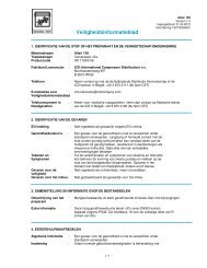
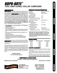
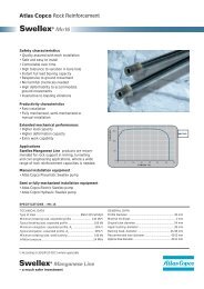
Rohrlängenbestimmung<br />
Rohr darf im Verschraubungsstutzen nicht<br />
auf Anschlag montiert werden.<br />
Richtige Rohrlängenbestimmungerfolgt durch<br />
Messen des Abstandes von Anschlag<br />
Stutzen zu Anschlag Stutzen.<br />
Je Rohranschluß ist dann, bis einschließlich<br />
Rohr AD 18 mm, 1,0 mm, ab Rohr<br />
AD 20 mm, 0,5 mm abzuziehen.<br />
Determining the tube length<br />
The tube must not be assembled against<br />
the tube abutment in the coupling body.<br />
First measure the distance between the tube<br />
abutments in the connecting couplings.<br />
Then deduct 1.0 mm from each end when<br />
using tubes having outside diameters up to<br />
and including 18 mm. For tube sizes of<br />
20 mm and upwards deduct 0.5 mm<br />
from each end.<br />
Determination des longueurs de tubes<br />
Le tube ne doit pas iHre monte en butee dans<br />
le corps du raccord. La longueur exacte<br />
d'un tube se mesure entre les deux butees<br />
des corps de raccords correspondants.<br />
Pour chaque raccordement, il faut alors<br />
deduire de cette longueur 1 mm pour les tubes<br />
ayant des 0 ext. jusqu'a 18 mm et 0,5 mm<br />
a partir des 0 ext. de 20 mm.<br />
Hinweis für die Montage von Schaftteilen:<br />
Bei Montage von Schaftteilen (angedrehte<br />
Rohrstutzen) unbedingt umdrehungsbezogen<br />
montieren.<br />
(Achtung!: Höherer Kraftaufwand). Es ist auf<br />
jeden Fall eine Montage im<br />
Vormontagestutzen durchzuführen.<br />
Bei Fertigmontage ist die Überwurfmutter<br />
mindestens 3/4 Umdrehung über den Punkt<br />
des deutlich spürbaren Kraftanstieges<br />
anzuziehen.<br />
Note about standpipe assembly:<br />
When assembling standpipes (tube body<br />
formed on a lathe) respect exactly<br />
the prescribed number of turns.<br />
(Attention!: Increase in force is required.)<br />
<strong>Assembly</strong> must be carried out in the<br />
pre-assemblyadaptor.<br />
In the case of final assembly the nut has<br />
to be tightened by at least 3/4 of a turn<br />
beyond the point of a noticeable increase<br />
in force.<br />
Remarque apropos du montage<br />
d'embouts lisses<br />
Lors du montage d'embouts lisses (embouts<br />
faconnes au tour), le montage doit se faire<br />
imperativement suivant le nombre de tours<br />
prescrits.<br />
(Attention!: Effort de serrage plus eleve.) Le<br />
montage doit etre effectue dans le bloc<br />
de presertissage.<br />
Au montage final, serrer I'ecrou au moins<br />
de 3/4 de tour a partir du point de resistance.<br />
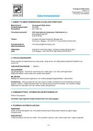
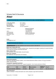
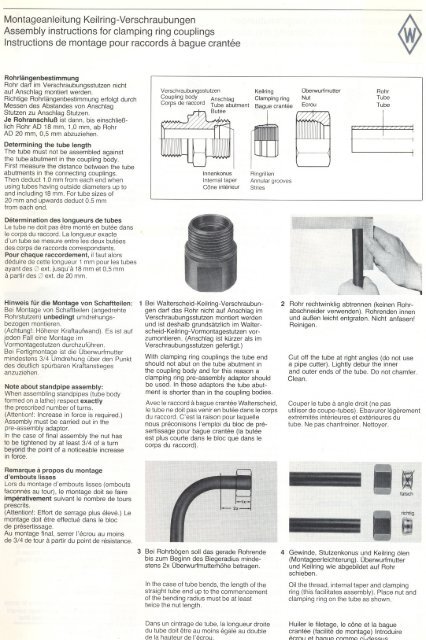
Verschraubungsstutzen <strong>Keilring</strong><br />
Coupling body Anschlag Clamping ring<br />
Corps de raccord Tube abutment Bague crantee<br />
Butee<br />
Innenkonus<br />
Internal taper<br />
Cone interieur<br />
1 Bei Walterscheid-<strong>Keilring</strong>-<strong>Verschraubungen</strong><br />
darf das Rohr nicht auf Anschlag im<br />
Verschraubungsstutzen montiert werden<br />
und ist deshalb grundsätzlich im Walterscheid-<strong>Keilring</strong>-Vorrnontagestutzenvorzumontieren.<br />
(Anschlag ist kürzer als im<br />
Verschraubungsstutzen gefertigt.)<br />
Ringrillen<br />
Annular grooves<br />
Stries<br />
With clamping ring couplings the tube end<br />
should not abut on the tube abutment in<br />
the coupling body and for this reason a<br />
clamping ring pre-assembly adaptor should<br />
be used. In these adaptors the tube abutment<br />
is shorter than in the coupling bodies.<br />
Avec le raccord a bague crantee Walterscheid,<br />
le tube ne doit pas venir en butee dans le corps<br />
du raccord. C'est la raison pour laquelle<br />
nous preconisons I'emploi du bloc de presertissage<br />
pour bague crantee (la butee<br />
est plus courte dans le bloc que dans le<br />
corps du raccord).<br />
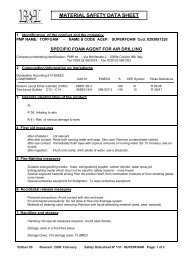
3 Bei Rohrbögen soll das gerade Rohrende<br />
bis zum Beginn des Biegeradius mindestens<br />
2x Überwurfmutterhöhe betragen.<br />
In the case of tube bends, the length of the<br />
straight tube end up to the commencement<br />
of the bending radius must be at least<br />
twice the nut length.<br />
Dans un eintrage de tube, la longueur droite<br />
du tube doit etre au moins egale au double<br />
de la hauteur de "ecrolJ<br />
überwurlmutter<br />
Nut<br />
Ecrou<br />
Rohr<br />
Tube<br />
Tube<br />
2 Rohr rechtwinklig abtrennen (keinen Rohrabschneider<br />
verwenden). Rohrenden innen<br />
und außen leicht entgraten. Nicht anfasen!<br />
Reinigen.<br />
Cut off the tube at righl"angles (do not use<br />
a pipe cutter). Lightly debur the inner<br />
and outer ends of the tube. 00 not chamfer.<br />
Clean.<br />
Couper le tube a angle droit (ne pas<br />
utiliser de coupe-tubes). Ebavurer legerement<br />
extremites interieures et exterieures du<br />
tube. Ne pas chanfreiner. Nettoyer.<br />
-<br />
1 1<br />
. falsch<br />
4 Gewinde, Stutzenkonus und <strong>Keilring</strong> ölen<br />
(Montageerleichterung). Überwurfmutter<br />
und <strong>Keilring</strong> wie abgebildet auf Rohr<br />
schieben.<br />
Oil the thread, internal taper and clamping<br />
ring (this facilitates assembly). Place nut and<br />
clamping ring on the tube as shown.<br />
Huiler le filetage, le cone et la bague<br />
crantee (facilite de montage) Introduire<br />
';'("'rnl' pt h~nllP ,.."mmp ,..i-riP~~, 1
MontageanlertungKellnng-<strong>Verschraubungen</strong><br />
<strong>Assembly</strong> <strong>instructions</strong> for clamping ring couplings<br />
Instructions de montage pour raccords a bague crantee<br />
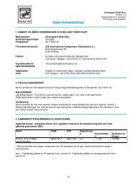
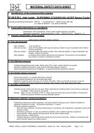
, 5 Rohr gegen Anschlag im Vormontagestutzen<br />
drücken. überwurfmutter von Hand<br />
festziehen.<br />
Hold the tupe end firmly against the tube<br />
abutment in the pre-assembly adaptor.<br />
fighten nut by hand.<br />
Visser I'ecrou a la main, le tube en butee<br />
~ dansle bloc.<br />
7 Kontrolle<br />
<strong>Keilring</strong> muß mit voller Länge gerade auf<br />
dem Rohr sitzen, darf sich drehen, jedoch<br />
nicht axial verschieben<br />
Check<br />
lassen.<br />
The fulllength of the clamping ring must<br />
be seated flush against the tube. Though<br />
permissible to turn, it must not be capable<br />
ofaxial dis placement.<br />
Controle<br />
La bague crantee doit etre sur le tube de<br />
toute sa longueur; elle peut tourner sur elle<br />
meme, mais ne pas se deplacer axialement.<br />
Montage<br />
im Verschraubungsstutzen<br />
Direct assembly<br />
in the coupling body<br />
Montage direct<br />
dans le corps de raccord<br />
Distanzring<br />
Spacer<br />
Entretoise<br />
6 überwurfmutter mit Schlüssel soweit anziehen,<br />
bis der <strong>Keilring</strong> das Rohr erfaßt hat<br />
(ca. 'h Umdrehung; wird durch Erreichen<br />
des Druckpunktes bzw. durch Kraftanstieg<br />
spürbar).<br />
Tighten nut with a spanner until the clamping<br />
ring gets into contact with the tube (approx. 1/2<br />
of a turn; critical pressure, Le. where a<br />
noticeable increase in force is required).<br />
Avec une clef, serrer I'ecrou jusque la<br />
bague crantee se trouve en contact avec<br />
le tube Ch tour; point de resistance).<br />
8 Fertigmontage<br />
stutzen<br />
im Verschraubungs-<br />
überwurfmutter 1/2 bis 3/4 Umdrehung<br />
über den Punkt des deutlich spürbaren<br />
Kraftanstieges anziehen. (Verschraubungsstutzen<br />
mit Schlüssel gegen halten).<br />
Final assembly in the coupling body.<br />
Tighten the nut half to three quarters<br />
of a turn beyond the point where a<br />
noticeable increase in force is required.<br />
(Hold the coupling<br />
a spanner).<br />
body firmly by means of<br />
Montage final dans le corps du raccord<br />
Serrage de I'ecrou de 1/2 a 3/4 de tour ci<br />
partir du moment de resistance. (Maintenir<br />
le corps du raccord avec une clef).<br />
Hinweis<br />
Bei einer möglichst zu vermeidenden<br />
Montage im Verschraubungsstutzenist<br />
unbedingt darauf zu achten, daß das Rohr<br />
nicht auf Anschlag montiert wird. .<br />
Information<br />
This method should be avoided but where<br />
it is not possible to use a pre-assembly tool<br />
it is most important to ensure that the tube<br />
end does not abut against the tube abutment<br />
in the coupling body.<br />
Remarque<br />
Pour ce montage (autant que possible a<br />
eviter) faire absolument attention a ce que<br />
le tube ne soit<br />
du raccord.<br />
pas en butee dans le corps<br />
Anschließend Vormontage mit 'h Umdrehung<br />
abschließen. Ringrillen sind in Rohroberfläche<br />
eingedrückt. <strong>Keilring</strong> ist auf<br />
dem Rohr fixiert.<br />
Then end pre-assembly operation by<br />
tightening nut half of a turn. Annular<br />
grooves are impressed in the tube surface.<br />
The clamping ring is fixed on to the tube.<br />
Apres, terminer I'operation de preassemblage<br />
par le serrage de J'ecrou de<br />
'h tour. Les stries penetrent dans le tube.<br />
La bague crantee est alors fixee sur le tube.<br />
9 Wiederholungsmontage<br />
Nach jedem Lösen der Verbindung ist der<br />
Wiederanzug der überwurfmutter ohne<br />
erhöhten Kraftaufwand vorzunehmen.<br />
(Verschraubungsstutzen<br />
gegenhalten).<br />
Re-assembly<br />
mit Schlüssel<br />
Each time coupling is disassembled the nut<br />
must be re-tightened without using<br />
excessive force whilst holding the coupling<br />
body firmly by means of a spanner.<br />
Remontage<br />
Apres un demontage, le serrage de I'ecrou,<br />
lors du remontage, doit se faire sans elfort<br />
excessif. (Maintenir le corps du raccord<br />
avec une clef).<br />
Montagehilfe<br />
Einlegen eines 2 mm*-Distanzringes in den<br />
Verschraubungsstutzen, anschließend<br />
MontaQe wie unter Bild 4 bis 7, Distanzring<br />
entfernen, Fertigmontage wie Bild 8.<br />
*LL-Reihe = 1 mm<br />
<strong>Assembly</strong>aid<br />
Insert a 2 mm thick* spacer in the coupling<br />
body, then carry out assembly as shown in<br />
figures 4-7. Remove the spacer and finally<br />
assemble as shown in figure 8.<br />
*LL-Series = 1 mm<br />
Facilite de montage<br />
Mettre une entretoise de 2 mm dans le corps<br />
du raccord, puis elfectuer le montage suivant<br />
fig. 4 a 7. Oter I'entretoise. Montage final<br />
suivant fig. 8.<br />
*Serie LL = 1 mm
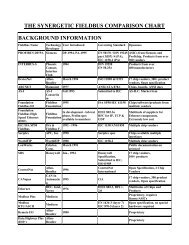
Vormontagestutzen<br />
Pre-assembly adaptor<br />
Blocde pre~sertissage<br />
tür <strong>Keilring</strong><br />
tor clamping ring<br />
pour bague crantee<br />
* Kerbe ist Kennzeichen für<br />
<strong>Keilring</strong>- Vormontagestutzen<br />
* Notch is marking for clamping ring<br />
pre-assembly adaptor *-<br />
*L'encassure est un marquage pour le bloc de<br />
pre-sertissage de la bague crantee<br />
Reihe Rohr-AD Typ Best.-Nr.<br />
Serles Tube OD Type Reference<br />
serie Tube
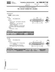
Rohr-Anschlußteile tür<strong>Keilring</strong>-<strong>Verschraubungen</strong><br />
Pipe connection parts torclamping ringcouplings<br />
Elements de raccords pour bague crantee<br />
Rohr-AD<br />
Überwurfmutter DIN 3870<br />
Nut DIN 3870<br />
Ecrou de blocage DIN 3870<br />
kg per<br />
100 St.<br />
<strong>Keilring</strong><br />
Clamping ring<br />
Bague crantee<br />
Tube 0'" kg per<br />
Reihe Tube Typ Best.-Nr. 100 pes. Typ Best.-Nr.<br />
Serles o ext. Type Reference kg par Type Reference<br />
Serie PN dN DesignationRef. 100p. M " S2 DesignationRef.<br />
kg per<br />
100 St.<br />
4 M 4 LL 039838 0,4 M 8x1 11 10 K-R 4 LL 028706 0,05 6<br />
LL 100 6. M 6 LL 039840 0,5 M 10x1 11,5 12 K-R 6 LL 028708 0,09 7,5<br />
L<br />
S<br />
400<br />
8 M 8 LL 039841 0,7 M 12x1 12 14 K-R 8 LL 028709 0,1 7,5<br />
6 M 6 L 039842 0,9 M 12x1,5 14,5 14 K-R 6 L/S 028710 0,15 9,5<br />
8 M 8L 039843 1,4 M 14x1,5 14,5 17 K-R 8 L/S 028711 0,2 9,5<br />
10 M 10L 039844 2,0 M 16x1,5 15,5 19 K-R 10 L/S 028712 0,25 10,5<br />
12 M 12L 039845 2,5 M 18x1,5 15,5 22 K-R 12 L/S 028713 0,3 10,5<br />
15 M 15 L 039846 4,0 M 22x1,5 17 27 K-R15L 028714 0,4 11<br />
18 M 18L 039847 6,0 M 26x1,5 18 32 K-R 18 L 028715 0,45 11,5<br />
22 M 22 L 039848 8,0 M 30x2 20 36 K-R 22 L 028716 0,6 12<br />
28 M 28L 039849 8,5 M 36x2 21 41 K-R 28 L 028717 0,75 12<br />
250 35 M 35L 039850 13,0 M 45x2 24 50 K-R 35 L 028718 1,7 14<br />
630<br />
400<br />
315<br />
42 M 42 L 039851 21,0 M 52x2 24 60 K-R 42 L 028719 2,1 14,5<br />
6 M 6S 039852 1,5 M 14x1,5 16,5 17 K-R 6 L/S 028710 0,15 9,5<br />
8 M 8 S 039853 1,7 M 16x1,5 16,5 19 K-R 8 L/S 028711 0,2 9,5<br />
10 M 10 S 039854 3,0 M 18x1,5 17,5 22 K-R 10 L/S 028712 0,25 10,5<br />
12 M 12S 039855 3,5 M 20x1,5 17,5 24 K-R 12 L/S 028713 0,3 10,5<br />
14 M 14 S 039856 5,0 M 22x1,5 20,5 27 K-R 14 S 028720 0,35 11<br />
16 M 16S 039857 6,0 M 24x1,5 20,5 30 K-R 16 S 028721 0,4 11,5<br />
20 M 20S 039858 9,5 M 30x2 24 36 K-R 20 S 028722 0,85 12,5<br />
25 M 25S 039859 19,5 M 36x2 27 46 K-R 25 S 028723 1,05 12,5<br />
30 M 30 S 039860 21,5 M 42x2 29 50 K-R 30 S 028724 1,45 14<br />
38 M 38S 039861 31,0 M 52x2 32,5 60 K-R 38 S 028725 1,90 14,5
Gerade-EI nschraubverschraubungen<br />
Male stud couplings<br />
Union simple male<br />
Einschraubgewinde: Whitworth-Rohrgewinde (zylindrisch)<br />
Stud thread: 8SP thread (parallel)<br />
Filetage mi'ile: Whitworth (cylindrique)<br />
K-GEV . . . . . . R<br />
DlN-ISO 228 (R. . . , DIN 259)<br />
kg per<br />
100St. 5,<br />
Reihe<br />
Serles<br />
Serie PN<br />
Tube OD<br />
Rohr-AD Tube<br />
o ext.<br />
1<br />
G<br />
Typ<br />
Type<br />
Designation<br />
Best.-Nr.<br />
Referenee<br />
RM.<br />
kg per<br />
100 pes.<br />
kg par<br />
100 p. l2 1 I d SI 52<br />
4 G 1/. A K-GEV 4 LLR 039082 1,8 19 9,5 8 14 14 10<br />
LL 100 6 G 1/. A K-GEV 6 LLR 039084 1,9 19,5 8 8 14 14 12<br />
8 G 1/. A K-GEV 8 LLR 039085 2,3 20,5 9 8 14 14 14<br />
6 G 1/. A K-GEV 6 LR 039086 2,5 23 8,5 8 14 14 14<br />
6 G 1/. A K-GEV 6 L/R 'I. 039087 4,1 24,5 10 12 18 19 14<br />
8 G 1/. A K-GEV 8 LR 039088 4,5 25 10 12 18 19 17<br />
8 G 3/. A K-GEV 8 L/R 3/. 039089 6,0 26 11,5 12 22 22 17<br />
10 G 1/. A K-GEV 10 LR 039090 4,7 26 11 12 18 19 19<br />
10 G 3/. A K-GEV 10 L/R 3/. 039091 M<br />
6,0 27 12,5 12 22 22 19<br />
400 10<br />
12<br />
G<br />
G<br />
112A<br />
1/. A<br />
K-GEV 10 L/R 112<br />
K-GEV 12 L/R '1.<br />
028099<br />
039092<br />
N<br />
z<br />
c.<br />
.c ..<br />
7,6 27,5<br />
6,0 27<br />
13<br />
12<br />
14<br />
12<br />
26<br />
18<br />
27<br />
19<br />
19<br />
22<br />
L 12 G 3/. A K-GEV 12 LR 039093 1:1 24,7 34 17,5 18 39 41 41<br />
35 G 11/. A K-GEV 35 LR 039099 40,7 39 17,5 20 49 50 50<br />
42<br />
6<br />
G 1112A<br />
G 1/. A<br />
K-GEV 42 LR<br />
K-GEV 6 SR<br />
039100<br />
039101<br />
5'. ...<br />
.:5.2<br />
Gi- - N:>:<br />
45,6<br />
5,0<br />
42<br />
28<br />
19<br />
13<br />
22<br />
12<br />
55<br />
18<br />
55<br />
19<br />
60<br />
17<br />
8 G 1/. A K-GEV 8 SR 039102 ';::00<br />
(/)a!O 5,5 30 15 12 18 19 19<br />
10 G 3/8 A K-GEV 10 SR 039103 8,2 31 15 12 22 22 22<br />
630 12 G 3/. A K-GEV 12 SR 039104 9,5 33 17 12 22 22 24<br />
12 G 112A K-GEV 12 SIR '12 039105 13,5 34 17,5 14 26 27 24<br />
S 14 G 112A K-GEV 14 SR 039106 14,8 37 19 14 26 27 27<br />
400<br />
315<br />
16 G 112A K-GEV 16 SR 039107 15,4 37 18,5 14 26 27 30<br />
20 G 3/. A K-GEV 20 SR 039108 25,3 42 20,5 16 32 32 36<br />
25 G1 A K-GEV 25 SR 039109 46,5 47 23 18 39 41 46<br />
30 G 11/. A K-GEV 30 SR 039110 64,4 50 23,5 20 49 50 50<br />
38 G 1112A K-GEV 38 SR 039111 88,9 sr 26 22 55 55 60<br />
L2ist Ungefährmaß bei angezogener Überwurfmutter<br />
L2= approximate length with nut tightened<br />
L2= longueur approximative, I'ecrou etant bloque<br />
. - 8 (Dichtkante Form 8, DIN3852)<br />
. - 8 (Studfaceform8, DIN3852)<br />
.- B (Ar€!ted'etancheite forme 8, DIN 3852)