Marine propeller with reverse thrust cup - European Patent Office ...
Marine propeller with reverse thrust cup - European Patent Office ...
Marine propeller with reverse thrust cup - European Patent Office ...

You also want an ePaper? Increase the reach of your titles
YUMPU automatically turns print PDFs into web optimized ePapers that Google loves.
EP 2 311 726 A1<br />
(19)<br />
(12) EUROPEAN PATENT APPLICATION<br />
(43) Date of publication:<br />
20.04.2011 Bulletin 2011/16<br />
(21) Application number: 10186494.0<br />
(22) Date of filing: 05.10.2010<br />
(84) Designated Contracting States:<br />
AL AT BE BG CH CY CZ DE DK EE ES FI FR GB<br />
GR HR HU IE IS IT LI LT LU LV MC MK MT NL NO<br />
PL PT RO RS SE SI SK SM TR<br />
Designated Extension States:<br />
BA ME<br />
(30) Priority: 16.10.2009 US 279082 P<br />
(71) Applicant: Powers, Charles Steven<br />
Shreveport LA 71106 (US)<br />
(54) <strong>Marine</strong> <strong>propeller</strong> <strong>with</strong> <strong>reverse</strong> <strong>thrust</strong> <strong>cup</strong><br />
(57) A marine <strong>propeller</strong> <strong>with</strong> <strong>reverse</strong> <strong>thrust</strong> <strong>cup</strong> includes<br />
a <strong>propeller</strong> hub, <strong>propeller</strong> blades each having a<br />
Printed by Jouve, 75001 PARIS (FR)<br />
(51) Int Cl.:<br />
B63H 1/26 (2006.01)<br />
<br />
(11) EP 2 311 726 A1<br />
(72) Inventor: Powers, Charles Steven<br />
Shreveport LA 71106 (US)<br />
(74) Representative: Gray, James et al<br />
Withers & Rogers LLP<br />
Goldings House<br />
2 Hays Lane<br />
London<br />
SE1 2HW (GB)<br />
leading blade face and a trailing blade face provided on<br />
the <strong>propeller</strong> hub and a <strong>reverse</strong> <strong>thrust</strong> <strong>cup</strong> provided in<br />
the trailing blade face of each of the <strong>propeller</strong> blades.
Description<br />
1 EP 2 311 726 A1<br />
2<br />
CROSS-REFERENCE TO RELATED APPLICATIONS<br />
[0001] This application claims the benefit of and incorporates<br />
by reference in its entirety U.S. provisional application<br />
no. 61/279,082, filed October 16, 2009 and entitled<br />
"MARINE PROPELLER WITH REVERSE THRUST<br />
CUP".<br />
FIELD<br />
[0002] The present disclosure relates to marine <strong>propeller</strong>s.<br />
More particularly, the present disclosure relates<br />
to a marine <strong>propeller</strong> having a <strong>reverse</strong> <strong>thrust</strong> <strong>cup</strong> provided<br />
in each blade of the <strong>propeller</strong> to minimize cavitation and<br />
enhance the <strong>reverse</strong> <strong>thrust</strong> capability of the <strong>propeller</strong>.<br />
BACKGROUND<br />
[0003] Recreational marine vehicles such as speedboats,<br />
ski boats, fishing boats, houseboats and the like<br />
commonly have a motor-driven drive system which includes<br />
a multibladed marine <strong>propeller</strong>. The <strong>propeller</strong> typically<br />
includes a hub from which extends multiple,<br />
spaced-apart <strong>propeller</strong> blades each having a leading face<br />
and a trailing face which is opposite the leading face.<br />
Each blade is oriented at an angle <strong>with</strong> respect to the<br />
rotational axis of the hub. Therefore, when the <strong>propeller</strong><br />
is submerged in a lake or other water body on which the<br />
marine vehicle floats and is rotated in a first direction, the<br />
leading face of each <strong>propeller</strong> blade applies rearward<br />
pressure against the water, propelling the marine vehicle<br />
forwardly on the water body. Conversely, when the <strong>propeller</strong><br />
is rotated in a second direction, the trailing face of<br />
each <strong>propeller</strong> blade applies forward pressure against<br />
the water, propelling the marine vehicle rearwardly on<br />
the water body.<br />
[0004] One of the problems which is frequently encountered<br />
in operating a marine vehicle in <strong>reverse</strong> results<br />
from cavitation of the water at the trailing face of each<br />
blade on the <strong>propeller</strong>. As the submerged <strong>propeller</strong> is<br />
rotated in water, the water accelerates around the edges<br />
of each blade, causing a reduction in water pressure at<br />
the trailing face of the blade until the pressure of the water<br />
eventually reaches the vapor pressure of the water. Consequently,<br />
cavitation occurs at the trailing face of the<br />
blade as the water vaporizes and small bubbles of air<br />
form in the water. Cavitation of the water at the trailing<br />
face of each blade when the vehicle is operated in <strong>reverse</strong><br />
typically results in vibration of the <strong>propeller</strong> and may compromise<br />
the <strong>reverse</strong> <strong>thrust</strong> capability of the marine vehicle.<br />
[0005] Therefore, a marine <strong>propeller</strong> having a <strong>reverse</strong><br />
<strong>thrust</strong> <strong>cup</strong> provided in each blade of the <strong>propeller</strong> to minimize<br />
cavitation and enhance the <strong>reverse</strong> <strong>thrust</strong> capability<br />
of the <strong>propeller</strong> is needed.<br />
5<br />
10<br />
15<br />
20<br />
25<br />
30<br />
35<br />
40<br />
45<br />
50<br />
55<br />
2<br />
SUMMARY<br />
[0006] The present disclosure is generally directed to<br />
a marine <strong>propeller</strong>. An illustrative embodiment of the marine<br />
<strong>propeller</strong> includes a <strong>propeller</strong> hub, <strong>propeller</strong> blades<br />
each having a leading blade face and a trailing blade face<br />
provided on the <strong>propeller</strong> hub and a <strong>reverse</strong> <strong>thrust</strong> <strong>cup</strong><br />
provided in the trailing blade face of each of the <strong>propeller</strong><br />
blades.<br />
BRIEF DESCRIPTION OF THE DRAWINGS<br />
[0007] The disclosure will now be made, by way of example,<br />
<strong>with</strong> reference to the accompanying drawings, in<br />
which:<br />
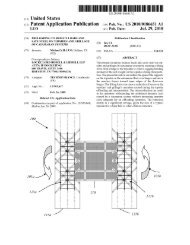
FIG. 1 is a rear perspective view of an illustrative<br />
embodiment of the marine <strong>propeller</strong> <strong>with</strong> <strong>reverse</strong><br />
<strong>thrust</strong> <strong>cup</strong>;<br />
FIG. 2 is a front view of an illustrative embodiment<br />
of the marine <strong>propeller</strong> <strong>with</strong> <strong>reverse</strong> <strong>thrust</strong> <strong>cup</strong>;<br />
FIG. 3 is a side view of an illustrative embodiment<br />
of the marine <strong>propeller</strong> <strong>with</strong> <strong>reverse</strong> <strong>thrust</strong> <strong>cup</strong>, taken<br />
along viewing lines 3-3 in FIG. 2;<br />
FIG. 4 is a sectional view, taken along section lines<br />
4-4 in FIG. 3, of a <strong>propeller</strong> blade of an illustrative<br />
embodiment of the marine <strong>propeller</strong> <strong>with</strong> <strong>reverse</strong><br />
<strong>thrust</strong> <strong>cup</strong>;<br />
FIG. 5 is a side view of an illustrative embodiment<br />
of the marine <strong>propeller</strong> <strong>with</strong> <strong>reverse</strong> <strong>thrust</strong> <strong>cup</strong>, taken<br />
along viewing lines 5-5 in FIG. 2;<br />
FIG. 6 is a side view of an alternative illustrative embodiment<br />
of the marine <strong>propeller</strong> <strong>with</strong> <strong>reverse</strong> <strong>thrust</strong><br />
<strong>cup</strong>, <strong>with</strong> a <strong>propeller</strong> blade illustrated in edge view;<br />
FIG. 7 is a side view of the alternative illustrative<br />
embodiment of the marine <strong>propeller</strong> <strong>with</strong> <strong>reverse</strong><br />
<strong>thrust</strong> <strong>cup</strong> illustrated in FIG. 6, <strong>with</strong> a <strong>propeller</strong> blade<br />
illustrated in rear view; and<br />
FIG. 8 is a side view of an illustrative embodiment<br />
of an inboard marine <strong>propeller</strong> <strong>with</strong> <strong>reverse</strong> <strong>thrust</strong><br />
<strong>cup</strong>, <strong>with</strong> a <strong>propeller</strong> blade illustrated in edge view.<br />
DETAILED DESCRIPTION<br />
[0008] The following detailed description is merely exemplary<br />
in nature and is not intended to limit the described<br />
embodiments or the application and uses of the<br />
described embodiments. As used herein, the word "exemplary"<br />
or "illustrative" means "serving as an example,<br />
instance, or illustration." All of the implementations described<br />
below are exemplary implementations provided
3 EP 2 311 726 A1<br />
4<br />
to enable persons skilled in the art to practice the disclosure<br />
and are not intended to limit the scope of the claims.<br />
Furthermore, there is no intention to be bound by any<br />
expressed or implied theory presented in the preceding<br />
technical field, background, brief summary or the following<br />
detailed description. As used herein, relative terms<br />
such as "fore" and "aft" are used for descriptive purposes<br />
only and not in a limiting sense.<br />
[0009] Referring to the drawings, an illustrative embodiment<br />
of the marine <strong>propeller</strong> <strong>with</strong> <strong>reverse</strong> <strong>thrust</strong> <strong>cup</strong>,<br />
hereinafter <strong>propeller</strong>, is generally indicated by reference<br />
numeral 1. The <strong>propeller</strong> 1 includes a generally elongated,<br />
cylindrical <strong>propeller</strong> hub 2 which may have a hub<br />
interior 3. In some embodiments, a shaft sleeve 6 may<br />
be provided in the hub interior 3. A shaft bearing 7 may<br />
be provided in the shaft sleeve 6. In use of the <strong>propeller</strong><br />
1, which will be hereinafter described, the shaft bearing<br />
7 may receive a <strong>propeller</strong> drive shaft 8 that is drivingly<br />
engaged by a marine engine (not illustrated) provided on<br />
a marine vehicle (not illustrated). The shaft bearing 7 may<br />
be coupled to the <strong>propeller</strong> drive shaft 8 in any suitable<br />
manner according to the knowledge of those skilled in<br />
the art. In some embodiments, the shaft bearing 7 may<br />
be coupled to the <strong>propeller</strong> drive shaft 8 using a splined<br />
coupling (not illustrated) as is well known by those skilled<br />
in the art. The <strong>propeller</strong> hub 2 may have a fore hub end<br />
2a which generally faces the marine vehicle (not illustrated)<br />
and an aft hub end 2b which generally faces away<br />
from the marine vehicle (not illustrated). A diffuser lip 4<br />
may flare outwardly from the aft hub end 2b of the <strong>propeller</strong><br />
hub 2 to reduce cavitation, as is known by those<br />
skilled in the art.<br />
[0010] Multiple <strong>propeller</strong> blades 10 extend radially or<br />
outwardly from the <strong>propeller</strong> hub 2 in spaced-apart relationship<br />
<strong>with</strong> respect to each other around the circumference<br />
of the <strong>propeller</strong> hub 2. Each <strong>propeller</strong> blade 10 may<br />
be attached to the <strong>propeller</strong> hub 2 along a blade/hub junction<br />
14 which is disposed at a selected angle <strong>with</strong> respect<br />
to a rotational axis 5 (FIG. 3) of the <strong>propeller</strong> hub 2. Each<br />
<strong>propeller</strong> blade 10 may have a generally curved outline,<br />
<strong>with</strong> a leading blade edge 11 which may be generally<br />
proximate to the fore hub end 2a; a trailing blade edge<br />
12 which may be generally proximate to the aft hub end<br />
2b; and an outer blade edge 13 which transitions the<br />
leading blade edge 11 to the trailing blade edge 12. Each<br />
<strong>propeller</strong> blade 10 has a leading blade face 16 which may<br />
generally face the aft hub end 2b of the <strong>propeller</strong> hub 2<br />
and a trailing blade face 17 which may generally face the<br />
fore hub end 2a of the <strong>propeller</strong> hub 2. In use of the<br />
<strong>propeller</strong> 1, which will be hereinafter described, the leading<br />
blade edge 11 and the leading blade face 16 of each<br />
<strong>propeller</strong> blade 10 rotate ahead of the trailing blade edge<br />
12 and the trailing blade face 17, respectively, of each<br />
<strong>propeller</strong> blade 10 when the marine vehicle (not illustrated)<br />
on which the <strong>propeller</strong> 1 is provided is operated in<br />
the forward direction on a water body (not illustrated).<br />
Conversely, the trailing blade edge 12 and the trailing<br />
blade face 17 of each <strong>propeller</strong> blade 10 rotate ahead of<br />
5<br />
10<br />
15<br />
20<br />
25<br />
30<br />
35<br />
40<br />
45<br />
50<br />
55<br />
3<br />
the leading blade edge 11 and the leading blade face 16,<br />
respectively, of each <strong>propeller</strong> blade 10 when the marine<br />
vehicle is operated in the <strong>reverse</strong> direction on the water<br />
body.<br />
[0011] As illustrated in FIG. 4, the trailing blade face<br />
17 may be generally convex whereas the leading blade<br />
face 16 of each <strong>propeller</strong> blade 10 may be generally concave<br />
in cross-section. A <strong>reverse</strong> <strong>thrust</strong> <strong>cup</strong> 20 having a<br />
generally convex <strong>cup</strong> surface 26 is provided in the trailing<br />
blade face 17 of each <strong>propeller</strong> blade 10. The <strong>reverse</strong><br />
<strong>thrust</strong> <strong>cup</strong> 20 may be cast, stamped, cut or otherwise<br />
provided in the trailing blade face 17 according to the<br />
knowledge of those skilled in the art.<br />
[0012] As illustrated in FIGS. 1 and 3, the <strong>reverse</strong> <strong>thrust</strong><br />
<strong>cup</strong> 20 in each <strong>propeller</strong> blade 10 may have a curved<br />
<strong>cup</strong> lip 21 which defines a boundary between the <strong>cup</strong><br />
surface 26 of the <strong>reverse</strong> <strong>thrust</strong> <strong>cup</strong> 20 and the remaining<br />
surface of the trailing blade face 17. In some embodiments,<br />
the <strong>cup</strong> lip 21 may include a curved radial lip portion<br />
22 which is oriented in generally radial relationship<br />
<strong>with</strong> respect to the <strong>propeller</strong> hub 2 and extends generally<br />
from the blade/hub junction 14 in generally parallel and<br />
spaced-apart relationship <strong>with</strong> respect to the leading<br />
blade edge 11 of the <strong>propeller</strong> blade 10. A curved outer<br />
lip portion 23 may continue the radial lip portion 22 of the<br />
<strong>cup</strong> lip 21 in generally spaced-apart relationship <strong>with</strong> respect<br />
to the outer blade edge 13 of the <strong>propeller</strong> blade<br />
10. The outer lip portion 23 may terminate at the trailing<br />
blade edge 12 of the <strong>propeller</strong> blade 10. A trailing <strong>cup</strong><br />
edge 24 may define the trailing boundary of the <strong>reverse</strong><br />
<strong>thrust</strong> <strong>cup</strong> 20 and may extend generally from the end of<br />
the outer lip portion 23 toward the blade/hub junction 14<br />
of the <strong>propeller</strong> blade 10. The trailing <strong>cup</strong> edge 24 may<br />
generally coincide <strong>with</strong> the trailing blade edge 12 of the<br />
<strong>propeller</strong> blade 10.<br />
[0013] In typical application, the <strong>propeller</strong> 1 is coupled<br />
to a <strong>propeller</strong> drive shaft 8 which is drivingly engaged by<br />
a marine engine (not illustrated) provided on a marine<br />
vehicle (not illustrated). Accordingly, the shaft bearing 7<br />
provided in the <strong>propeller</strong> hub 2 of the <strong>propeller</strong> 1 receives<br />
the <strong>propeller</strong> drive shaft 8, <strong>with</strong> the fore hub end 2a of<br />
the <strong>propeller</strong> hub 2 generally facing toward the marine<br />
vehicle and the aft hub end 2b of the <strong>propeller</strong> hub 2<br />
generally facing away from the marine vehicle. The shaft<br />
bearing 7 may be coupled to the <strong>propeller</strong> drive shaft 8<br />
according to any suitable attachment technique which is<br />
known by those skilled in the art.<br />
[0014] As the marine vehicle is placed on a lake or<br />
other water body (not illustrated), the <strong>propeller</strong> 1 is submerged<br />
in the water body. In forward operation of the<br />
marine vehicle on the water body, the <strong>propeller</strong> drive shaft<br />
8 rotates the <strong>propeller</strong> 1 in the clockwise direction illustrated<br />
in FIG. 2, as indicated by the forward rotation arrow<br />
28, such that the leading blade face 16 of each <strong>propeller</strong><br />
blade 10 applies rearward pressure against the water in<br />
the water body. Consequently, the water pushes forwardly<br />
against each <strong>propeller</strong> blade 10, propelling the marine<br />
vehicle forwardly on the water body typically in the con-
5 EP 2 311 726 A1<br />
6<br />
ventional manner.<br />
[0015] In rearward operation of the marine vehicle on<br />
the water body, the <strong>propeller</strong> drive shaft 8 rotates the<br />
<strong>propeller</strong> 1 in the counterclockwise direction illustrated<br />
in FIG. 2, as indicated by the <strong>reverse</strong> rotation arrow 29.<br />
Therefore, the trailing blade face 17 of each <strong>propeller</strong><br />
blade 10 applies forward pressure against the water in<br />
the water body. Consequently, the water pushes rearwardly<br />
against each <strong>propeller</strong> blade 10, propelling the<br />
marine vehicle rearwardly on the water body.<br />
[0016] As illustrated in FIG. 4, throughout <strong>reverse</strong> rotation<br />
of the <strong>propeller</strong> 1, as indicated by the <strong>reverse</strong> rotation<br />
arrow 29, the trailing blade edge 12 of each <strong>propeller</strong><br />
blade 10 presents a gentle angle of attack to the<br />
water 32 in the water body, minimizing cavitation and<br />
drag on the <strong>propeller</strong> 1. Water 32 in the water body initially<br />
traverses the trailing blade edge 12 of each <strong>propeller</strong><br />
blade 10 and then flows across the <strong>cup</strong> surface 26 and<br />
then strikes the <strong>cup</strong> lip 21 of the <strong>reverse</strong> <strong>thrust</strong> <strong>cup</strong> 20.<br />
It will be appreciated by those skilled in the art that the<br />
<strong>cup</strong> lip 21 deflects the trajectory of the water 32 away<br />
from the <strong>propeller</strong> blade 10. Consequently, cavitation of<br />
the water 32 at the <strong>reverse</strong> <strong>thrust</strong> <strong>cup</strong> 20 is eliminated or<br />
substantially reduced, enhancing the <strong>reverse</strong> <strong>thrust</strong> of<br />
the marine vehicle as well as enabling the operator of<br />
the marine vehicle to more precisely control the <strong>reverse</strong><br />
speed of the marine vehicle on the water body.<br />
[0017] It will be appreciated by those skilled in the art<br />
that the <strong>propeller</strong> <strong>with</strong> <strong>reverse</strong> <strong>thrust</strong> <strong>cup</strong> 1 may be manufactured<br />
using any of the metalworking, casting or other<br />
known or yet to be developed marine <strong>propeller</strong> fabrication<br />
methods. The <strong>propeller</strong> 1 may be constructed of any suitable<br />
material which is used to fabricate marine <strong>propeller</strong>s<br />
including aluminum, bronze, stainless steel and composite<br />
materials, for example and <strong>with</strong>out limitation. The <strong>reverse</strong><br />
<strong>thrust</strong> <strong>cup</strong> 20 may be cast into the trailing blade<br />
face 17 of each <strong>propeller</strong> blade 10 or may be provided<br />
in the trailing blade face 17 using cutting, stamping, machining<br />
or other suitable techniques known by those<br />
skilled in the art. Moreover, the <strong>propeller</strong> 1 is suitable for<br />
enhancing the <strong>reverse</strong> <strong>thrust</strong> capability of a variety of<br />
marine vehicles including speedboats, ski boats, fishing<br />
boats and houseboats, for example and <strong>with</strong>out limitation,<br />
and may be applicable to any type of marine engine<br />
including inboard engines, outboard engines or inboard/<br />
outboard engines, for example and <strong>with</strong>out limitation. Additionally,<br />
many outboard and sterndrive <strong>propeller</strong>s discharge<br />
exhaust gas through the open sections of the hub<br />
interior 3. In forward operation, these gases are discharged<br />
behind the <strong>propeller</strong> blades 10 and in most cases<br />
have little effect on forward <strong>thrust</strong>. However, in <strong>reverse</strong><br />
operation, these exhaust gases are being discharged directly<br />
into the path of the <strong>propeller</strong> blades 10, producing<br />
a gaseous aeration of the water. In such operations, the<br />
<strong>reverse</strong> <strong>thrust</strong> <strong>cup</strong> 20 helps greatly in controlling slippage<br />
between the <strong>propeller</strong> blades 10 and the water due to<br />
the described aeration.<br />
[0018] Referring next to FIGS. 6-8 of the drawings, an<br />
5<br />
10<br />
15<br />
20<br />
25<br />
30<br />
35<br />
40<br />
45<br />
50<br />
55<br />
4<br />
alternative illustrative embodiment of the marine <strong>propeller</strong><br />
<strong>with</strong> <strong>reverse</strong> <strong>thrust</strong> <strong>cup</strong> is generally indicated by reference<br />
numeral 1a in FIGS. 6 and 7. The <strong>propeller</strong> 1a<br />
may have a design which is similar to that of the <strong>propeller</strong><br />
1 which was heretofore described <strong>with</strong> respect to FIGS.<br />
1-5. In the <strong>propeller</strong> 1a, the <strong>cup</strong> lip 21 may have a tapered<br />
radial lip portion 22a the thickness of which gradually<br />
tapers toward the blade/hub junction 14. Accordingly, as<br />
illustrated in FIG. 7, a water flow path 34 is defined between<br />
the tapered radial lip portion 22a and the blade/hub<br />
junction 14. The water flow path 34 provides a substantially<br />
unhindered path for flow of water as the <strong>propeller</strong><br />
la is operated in <strong>reverse</strong>. An inboard marine <strong>propeller</strong> 1b<br />
having a tapered radial lip portion 22a is illustrated in<br />
FIG. 8.<br />
[0019] Referring next to FIGS. 9-11 of the drawings,<br />
another alternative illustrative embodiment of the marine<br />
<strong>propeller</strong> <strong>with</strong> <strong>reverse</strong> <strong>thrust</strong> <strong>cup</strong> is generally indicated<br />
by reference numeral 1cin FIGS. 9 and 10. The <strong>propeller</strong><br />
1c may have a design which is similar to that of the <strong>propeller</strong><br />
1 which was heretofore described <strong>with</strong> respect to<br />
FIGS. 1-5. In the <strong>propeller</strong> 1c, the <strong>cup</strong> lip 21 may have a<br />
truncated radial lip portion 22b which terminates in<br />
spaced-apart relationship to the blade/hub junction 14.<br />
Accordingly, as illustrated in FIG. 10, a water flow path<br />
34 is defined between the truncated radial lip portion 22b<br />
and the blade/hub junction 14. The water flow path 34<br />
provides a substantially unhindered path for flow of water<br />
as the <strong>propeller</strong> 1 is operated in <strong>reverse</strong>. An inboard marine<br />
<strong>propeller</strong> 1d having a truncated radial lip portion 22b<br />
is illustrated in FIG. 11.<br />
[0020] While the preferred embodiments of the disclosure<br />
have been described above, it will be recognized<br />
and understood that various modifications can be made<br />
in the disclosure and the appended claims are intended<br />
to cover all such modifications which may fall <strong>with</strong>in the<br />
spirit and scope of the disclosure.<br />
Claims<br />
1. A marine <strong>propeller</strong>, comprising:<br />
a <strong>propeller</strong> hub;<br />
a plurality of <strong>propeller</strong> blades each having a<br />
leading blade face and a trailing blade face carried<br />
by said <strong>propeller</strong> hub; and<br />
a <strong>reverse</strong> <strong>thrust</strong> <strong>cup</strong> provided in said trailing<br />
blade face of each of said plurality of <strong>propeller</strong><br />
blades.<br />
2. The marine <strong>propeller</strong> of claim 1 wherein said <strong>reverse</strong><br />
<strong>thrust</strong> <strong>cup</strong> comprises a <strong>cup</strong> lip provided in said trailing<br />
blade face.<br />
3. The marine <strong>propeller</strong> of claim 2 wherein said <strong>cup</strong> lip<br />
comprises a radial lip portion extending generally radially<br />
<strong>with</strong> respect to said <strong>propeller</strong> hub and an outer
7 EP 2 311 726 A1<br />
8<br />
lip portion extending from said radial lip portion.<br />
4. The marine <strong>propeller</strong> of claim 3 further comprising a<br />
generally convex <strong>cup</strong> surface extending from said<br />
<strong>cup</strong> lip.<br />
5. The marine <strong>propeller</strong> of claim 3 or claim 4 further<br />
comprising a trailing <strong>cup</strong> edge extending from said<br />
outer lip portion.<br />
6. The marine <strong>propeller</strong> of one of claims 3 to 5 further<br />
comprising a water flow path between said radial lip<br />
portion of said <strong>cup</strong> lip and said <strong>propeller</strong> hub.<br />
7. A marine <strong>propeller</strong> as claimed in claim 1, wherein<br />
each of said <strong>propeller</strong> blades has a leading blade<br />
edge, an outer blade edge and a trailing blade edge;<br />
and<br />
said <strong>reverse</strong> <strong>thrust</strong> <strong>cup</strong> is bounded by said outer<br />
blade edge and said trailing blade edge.<br />
8. The marine <strong>propeller</strong> of claim 7 wherein said <strong>reverse</strong><br />
<strong>thrust</strong> <strong>cup</strong> comprises a <strong>cup</strong> lip provided in said trailing<br />
blade face and wherein said <strong>reverse</strong> <strong>thrust</strong> <strong>cup</strong> is<br />
further bounded by said <strong>cup</strong> lip.<br />
9. The marine <strong>propeller</strong> of claim 8 further comprising a<br />
generally convex <strong>cup</strong> surface extending from said<br />
<strong>cup</strong> lip.<br />
10. The marine <strong>propeller</strong> of claim 8 wherein said <strong>cup</strong> lip<br />
comprises a radial lip portion extending generally radially<br />
<strong>with</strong> respect to said <strong>propeller</strong> hub and an outer<br />
lip portion extending from said radial lip portion.<br />
11. The marine <strong>propeller</strong> of claim 10 further comprising<br />
a trailing <strong>cup</strong> edge extending from said outer lip portion.<br />
12. The marine <strong>propeller</strong> of claim 10 or claim 11 further<br />
comprising a water flow path between said radial lip<br />
portion of said <strong>cup</strong> lip and said <strong>propeller</strong> hub.<br />
13. A marine <strong>propeller</strong> as claimed in claim 1, wherein<br />
each of said <strong>propeller</strong> blades has a leading blade<br />
edge, an outer blade edge and a trailing blade edge<br />
carried by said <strong>propeller</strong> hub; and<br />
wherein said <strong>reverse</strong> <strong>thrust</strong> <strong>cup</strong> includes a <strong>cup</strong> lip<br />
having a radial lip portion generally parallel and<br />
spaced-apart <strong>with</strong> respect to said leading blade edge<br />
and an outer lip portion generally spaced-apart <strong>with</strong><br />
respect to the outer blade edge, and a <strong>cup</strong> lip bounded<br />
by said <strong>cup</strong> lip, said outer blade edge and said<br />
trailing blade edge.<br />
14. The marine <strong>propeller</strong> of claim 13 further comprising<br />
a water flow path between said radial lip portion of<br />
said <strong>cup</strong> lip and said <strong>propeller</strong> hub.<br />
5<br />
10<br />
15<br />
20<br />
25<br />
30<br />
35<br />
40<br />
45<br />
50<br />
55<br />
5<br />
15. The marine <strong>propeller</strong> of claim 6, 12 or 14 wherein<br />
said radial lip portion comprises a tapered radial lip<br />
portion.<br />
16. The marine <strong>propeller</strong> of claim 6, 12 or 14 wherein<br />
said radial lip portion comprises a truncated radial<br />
lip portion.
EP 2 311 726 A1<br />
6
EP 2 311 726 A1<br />
7
EP 2 311 726 A1<br />
8
EP 2 311 726 A1<br />
9
EP 2 311 726 A1<br />
10
EP 2 311 726 A1<br />
11
REFERENCES CITED IN THE DESCRIPTION<br />
EP 2 311 726 A1<br />
This list of references cited by the applicant is for the reader’s convenience only. It does not form part of the <strong>European</strong><br />
patent document. Even though great care has been taken in compiling the references, errors or omissions cannot be<br />
excluded and the EPO disclaims all liability in this regard.<br />
<strong>Patent</strong> documents cited in the description<br />
• US 61279082 A [0001]<br />
12