An approach to computerized preliminary design procedure of mid ...
An approach to computerized preliminary design procedure of mid ...
An approach to computerized preliminary design procedure of mid ...

You also want an ePaper? Increase the reach of your titles
YUMPU automatically turns print PDFs into web optimized ePapers that Google loves.
Inter J Nav Archit Oc Engng (2010) 2:96~103<br />
DOI 10.3744/JNAOE.2010.2.2.096<br />
<strong>An</strong> <strong>approach</strong> <strong>to</strong> <strong>computerized</strong> <strong>preliminary</strong> <strong>design</strong> <strong>procedure</strong> <strong>of</strong> <strong>mid</strong>-size superyachts<br />
from hull modeling <strong>to</strong> interior space arrangement<br />
Jong-Ho Nam 1 , Dong-Ham Kim 2 and Ho Jin Lee 1<br />
1 College <strong>of</strong> Ocean Science and Technology, Korea Maritime University, Busan, Korea<br />
2 Wingship Technology, Daejon, Korea<br />
ABSTRACT: A concept <strong>of</strong> <strong>preliminary</strong> <strong>design</strong> for <strong>mid</strong>-size superyachts is explored. First, the pr<strong>of</strong>ile <strong>of</strong> a superyacht is<br />
interactively <strong>design</strong>ed with the help <strong>of</strong> freeform curve functionality and graphical user interface (GUI) based interaction. The<br />
hull form is then constructed using major characteristic curves such as <strong>design</strong> waterline, deck sideline, and sections in addition<br />
<strong>to</strong> the predefined pr<strong>of</strong>ile curve. After exterior hull modeling is done, the arrangement <strong>of</strong> significant interior spaces <strong>of</strong> all decks<br />
is carried out. A genetic algorithm is exploited <strong>to</strong> find a space arrangement by considering space fitness values, space proximity,<br />
and stairs connectivity <strong>of</strong> relevant spaces. A goal <strong>of</strong> the paper is <strong>to</strong> <strong>of</strong>fer a step-by-step <strong>procedure</strong> for superyacht <strong>design</strong> from<br />
scratch or when initial information is not sufficient for complete <strong>design</strong>. For this purpose, a GUI based superyacht <strong>design</strong><br />
system is developed. This <strong>design</strong> <strong>approach</strong> is expected <strong>to</strong> help users interactively <strong>design</strong> <strong>mid</strong>-size superyachts.<br />
KEY WORDS: Superyacht; CAD; Modeling; Genetic algorithm; Interior space arrangement.<br />
INTRODUCTION<br />
Superyacht industry is a high added-valued market and<br />
its potential buying power has grown steadily. It is not new<br />
but recently has drawn attention as an emerging item in<br />
shipbuilding industries. Unlike other commercial vessels, the<br />
superyacht <strong>design</strong> emphasizes style and luxury, even though<br />
engineering is still an important aspect. Superyachts have<br />
been traditionally built in European countries where the<br />
selling amount and employment in <strong>mid</strong>dle-sized shipyards<br />
have been on the rise.<br />
The size <strong>of</strong> superyachts has increased. Recent reports<br />
reveal that superyachts <strong>of</strong> at least 24 meters have dominated<br />
the market. As <strong>of</strong> 2006, the superyacht market share shows<br />
that Italy stands at the <strong>to</strong>p with 37.8%, followed by United<br />
States with 12.4%, Netherlands and United Kingdom with<br />
7~8%, and then Germany and New Zealand (Kim, 2008).<br />
Although Korean shipbuilding industry has basic technology,<br />
it falls behind in the field <strong>of</strong> various supplementary<br />
equipment and luxurious interior <strong>design</strong>.<br />
Superyachts are relatively new and undeveloped in<br />
regards <strong>to</strong> <strong>design</strong> and technology. Research results <strong>of</strong> their<br />
<strong>design</strong> and construction are seldom available, which makes it<br />
difficult <strong>to</strong> make strides with superyacht <strong>design</strong>. Preliminary<br />
work has been published by Nam et al. (2007) but the content<br />
was limited <strong>to</strong> partial modeling <strong>of</strong> a superyacht and did not<br />
deal with a comprehensive <strong>design</strong>. In comparison <strong>to</strong> research<br />
on exterior <strong>design</strong> <strong>of</strong> superyachts, researches on interior<br />
<strong>design</strong> <strong>of</strong> superyachts are scarcer. No guideline on space<br />
arrangement has been known <strong>to</strong> the authors except the<br />
analysis <strong>of</strong> current layout (Lee and Byun, 2007). Most<br />
interior <strong>design</strong>s are executed by some experts in advanced<br />
shipbuilding countries. Therefore, a <strong>preliminary</strong> guideline for<br />
the superyacht <strong>design</strong> is strongly desired <strong>to</strong> help the <strong>design</strong>er<br />
find a good starting point. Even the experts can verify their<br />
<strong>design</strong> using the guideline suggested here.<br />
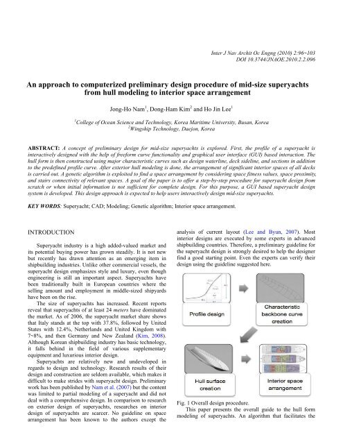
Fig. 1 Overall <strong>design</strong> <strong>procedure</strong>.<br />
This paper presents the overall guide <strong>to</strong> the hull form<br />
modeling <strong>of</strong> superyachts. <strong>An</strong> algorithm that facilitates the
Inter J Nav Archit Oc Engng (2010) 2:96~103 97<br />
interior space arrangement is implemented. The overall<br />
<strong>design</strong> flow is depicted in Fig.1.<br />
DETERMINATION OF PROFILE CURVE<br />
One way <strong>to</strong> generate the hull form is <strong>to</strong> build up a surface<br />
over a set <strong>of</strong> backbone curves. The hull form <strong>of</strong> the<br />
superyacht is not easy <strong>to</strong> standardize because its shape is<br />
very unique and different from that <strong>of</strong> conventional vessels.<br />
In this research, the pr<strong>of</strong>ile curve is selected as a key curve<br />
that characterizes the outline <strong>of</strong> hull form. The purpose <strong>of</strong><br />
<strong>design</strong>ing with the pr<strong>of</strong>ile curve is <strong>to</strong> consider the<br />
engineering as well as the aesthetic point <strong>of</strong> view.<br />
As superyachts have their own characteristic shapes and<br />
are different from each other, it is known <strong>to</strong> be difficult <strong>to</strong><br />
directly <strong>design</strong> the whole pr<strong>of</strong>ile curve. As a remedy, it is<br />
suggested that the pr<strong>of</strong>ile curve be divided in<strong>to</strong> the zones.<br />
Each zone is <strong>design</strong>ed separately <strong>to</strong> be merged later.<br />
The pr<strong>of</strong>ile curve is defined by the NURBS<br />
representation (Piegl and Tiller, 1995; Rogers, 2001). The<br />
piecewise pr<strong>of</strong>ile curve in each zone is <strong>design</strong>ed using the<br />
parameters that characterize the curve and those piecewise<br />
curves are later merged in<strong>to</strong> a single pr<strong>of</strong>ile curve by<br />
imposing the necessary continuity across neighboring zones.<br />
Pr<strong>of</strong>ile shape can be modified by interactively changing the<br />
parameter values. To make the <strong>design</strong> process more intuitive,<br />
the graphical user interface that enables the construction as<br />
well as the modification <strong>of</strong> the existing shape is constructed.<br />
Fig.2 shows an example <strong>of</strong> the dialog box that manipulates<br />
five parameters <strong>to</strong> <strong>design</strong> a flat type bow. The five<br />
parameters consist <strong>of</strong> two pairs <strong>of</strong> control points in xz plane<br />
and a scalar fac<strong>to</strong>r C that controls the fullness <strong>of</strong> stem.<br />
HULL SURFACE MODELING<br />
In general, the three-dimensional geometric data <strong>of</strong> a ship<br />
is necessary in order <strong>to</strong> model the hull form. Unfortunately,<br />
these data for superyachts are not easy <strong>to</strong> obtain and, if<br />
available, it is not easy <strong>to</strong> use conventional hull variation<br />
techniques that treat the existing ship as a mother ship,<br />
because <strong>of</strong> the unique and special hull shape <strong>of</strong> superyachts.<br />
Bearing in mind that our goal is <strong>to</strong> suggest a guideline for the<br />
overall <strong>design</strong> <strong>of</strong> a superyacht rather than <strong>to</strong> perform a<br />
detailed <strong>design</strong> <strong>of</strong> hull form, we carry out a direct hull form<br />
modeling without using the concept <strong>of</strong> a mother ship.<br />
A modeling technique presented in this research is <strong>to</strong><br />
interactively determine the major characteristic curves and<br />
then <strong>to</strong> generate an outer hull surface based on those major<br />
curves. This technique is not new and the concept is similar<br />
<strong>to</strong> that <strong>of</strong> l<strong>of</strong>ting, sweeping, or skinning, all <strong>of</strong> which are<br />
popular surface generation techniques used in modern CAD<br />
systems (Woodward, 1988; Piegl and Tiller, 1995). Preparing<br />
adequate characteristic and spine curves in advance is<br />
necessary <strong>to</strong> obtain accurate results from those techniques,.<br />
One <strong>of</strong> the concerns in regards <strong>to</strong> generating a correct<br />
hull form is how <strong>to</strong> determine the ‘appropriate’ characteristic<br />
curves from a superyacht that may contain very eccentric<br />
shape in stern or stem. Commercial CAD packages are<br />
utilized <strong>to</strong> model the major curves and the hull surface. High<br />
level packages such UGNX (2008) and solidThinking (2009)<br />
are used <strong>to</strong> confirm the possibility <strong>of</strong> skinning process from<br />
prepared major curves, while the popular Rhino3D (2009) is<br />
adopted <strong>to</strong> generate final surfaces.<br />
In this work, the characteristic spine curves are a <strong>design</strong><br />
waterline, a deck sideline, and multiple sections. If the stern<br />
has sharply corners or unnatural geometric shape, however, it<br />
is recommended <strong>to</strong> include more curves that support the<br />
skinning process.<br />
Determination <strong>of</strong> <strong>design</strong> waterline and deck sideline<br />
Fig. 2 Dialog for stem <strong>design</strong>.<br />
The waterline at draft and the deck sideline are<br />
significant fac<strong>to</strong>rs in determining the hull form. In most ships,<br />
even in superyachts, those two curves are assumed <strong>to</strong> be<br />
similar in shape and thus, the same modeling technique can<br />
be applied <strong>to</strong> them. This assumption is still valid in this work<br />
but the <strong>design</strong>er should be entitled <strong>to</strong> greater freedom without<br />
being restricted by the assumption.<br />
Determining the waterline at draft, also known as <strong>design</strong><br />
waterline, can be categorized as two methods: the one that<br />
uses the numerical values from hydrostatic and/or<br />
hydrodynamic calculations, and the other that emphasizes the<br />
stylish shape. The former method uses the functional values<br />
such as area, longitudinal center <strong>of</strong> floatation (LCF), and<br />
entrance angle <strong>of</strong> waterline at draft. The control points <strong>of</strong> the<br />
curve representing the waterline are determined so that the<br />
given values are satisfied by the final curve. On the other<br />
hand, it is more natural <strong>to</strong> stress the style <strong>of</strong> superyachts on<br />
the basis <strong>of</strong> minimal geometric requirements, such as<br />
necessary spaces for equipment and rooms. In this work, the<br />
latter <strong>approach</strong> is adopted <strong>to</strong> generate more smooth and<br />
natural waterline at draft.
98 Inter J Nav Archit Oc Engng (2010) 2:96~103<br />
Technically, an arbitrary, rough NURBS curve that<br />
approximates the waterline is prepared in advance and its<br />
control points are interactively adjusted <strong>to</strong> converge the final<br />
shape. Unfortunately, moving a set <strong>of</strong> control points <strong>to</strong>gether<br />
<strong>to</strong> reach the desired shape by satisfying specified values is<br />
tricky and inefficient. The <strong>approach</strong> introduced in this<br />
research is <strong>to</strong> select a minimal set <strong>of</strong> <strong>design</strong> parameters that<br />
represent the waterline and <strong>to</strong> manipulate the parameters <strong>to</strong><br />
generate the desired waterline, following the same concept<br />
used in the pr<strong>of</strong>ile <strong>design</strong>.<br />
If the user demands certain functional values such as<br />
waterplane area or LCF, an interactive algorithm computes<br />
the area and LCF numerically at each <strong>design</strong> stage until the<br />
satisfac<strong>to</strong>ry values are fulfilled. The similar problem that<br />
determined the <strong>design</strong> parameters <strong>of</strong> the area and the<br />
longitudinal center <strong>of</strong> buoyancy in a commercial vessel was<br />
introduced by the author (Nam and Parsons, 2000). Rather<br />
than applying the interactive <strong>design</strong> <strong>approach</strong>, the problem<br />
was formulated in<strong>to</strong> an optimization problem and was solved<br />
numerically. This numerical <strong>approach</strong> can be applied <strong>to</strong> the<br />
current problem if the functional values are available in<br />
advance, which is not the case <strong>of</strong> superyacht <strong>design</strong>.<br />
Determination <strong>of</strong> sectional shape<br />
To determine a hull form, its geometric information<br />
should be available in advance. A traditional and convenient<br />
way is <strong>to</strong> use the two dimensional information, called<br />
sections, at key stations. Sections usually satisfy the<br />
engineering requirements imposed by a naval architect, such<br />
as area, center <strong>of</strong> mass, and other geometric constraints. Thus<br />
it is imperative <strong>to</strong> provide the accurate information <strong>of</strong><br />
sections <strong>to</strong> generate a desired hull form.<br />
Three characteristic curves, pr<strong>of</strong>ile, waterline at draft,<br />
and deck sideline, are used <strong>to</strong> <strong>design</strong> sections. As seen in<br />
Fig.3, the pr<strong>of</strong>ile determines the vertical position <strong>of</strong> the<br />
section bot<strong>to</strong>m while the waterline at draft and the deck<br />
sideline impose geometric constraints horizontally. A section<br />
must intersect with those three curves.<br />
A section can be determined numerically by the<br />
optimization technique as well. The problem is converted<br />
in<strong>to</strong> a minimization problem that determines the section<br />
based on the required functional values. A common and<br />
reasonable <strong>approach</strong> is <strong>to</strong> use the section area and the vertical<br />
center <strong>of</strong> floatation (VCF), as formulated in Eq.(1):<br />
Minimize f(X) subject <strong>to</strong> g(X) (1)<br />
where X is a vec<strong>to</strong>r <strong>of</strong> control points <strong>of</strong> a section curve <strong>to</strong> be<br />
determined, f(X) is the scalar value represented in sum <strong>of</strong> the<br />
differences between desired and obtained values <strong>of</strong> area and<br />
VCF, and g(X) is a set <strong>of</strong> constraints used <strong>to</strong> assign the<br />
geometric shape <strong>of</strong> the section. With the two <strong>design</strong><br />
parameters, f(X) is expressed as:<br />
f (X) w 1<br />
(A d<br />
A a<br />
) 2 w 2<br />
(V d<br />
V a<br />
) 2 (2)<br />
where w i is the weighting fac<strong>to</strong>rs controlling the contribution<br />
<strong>of</strong> the two parameters, A and V represent the area and VCF<br />
respectively, and subscript d denotes desired and o obtained.<br />
A weakness <strong>of</strong> the above formulation is that the <strong>design</strong>er<br />
must have an idea as <strong>to</strong> what the values <strong>of</strong> the section area<br />
and VCF are in advance. Conventional commercial ships are<br />
<strong>design</strong>ed from the <strong>of</strong>fset table and thus the geometric<br />
information and other functional values are available from<br />
simple and direct calculations. However, this kind <strong>of</strong><br />
scenario may not go along with superyacht <strong>design</strong>, as the hull<br />
form <strong>of</strong> a superyacht is likely <strong>to</strong> directly be <strong>design</strong>ed from<br />
stylist’s sketches in some cases. Therefore, dealing with the<br />
area or VCF in the earlier <strong>design</strong> stage is not practical.<br />
Fortunately, as suggested in the pr<strong>of</strong>ile and other<br />
characteristic curves’ <strong>design</strong> processes, it may be plausible <strong>to</strong><br />
interactively <strong>design</strong> the sections with the emphasis on styling<br />
aspects. In this work, control points are adjusted <strong>to</strong> obtain a<br />
desired section with a set <strong>of</strong> geometric constraints that<br />
restrict the shape <strong>of</strong> a section. Nonetheless, an option <strong>to</strong> use<br />
the area and VCF as constraints should not be neglected. A<br />
dialog that determines a section is depicted in Fig.4.<br />
Fig. 3 Intersection <strong>of</strong> section with pr<strong>of</strong>ile, waterline at draft,<br />
and deck sideline.<br />
Fig. 4 Dialog for interactive section <strong>design</strong>.
Inter J Nav Archit Oc Engng (2010) 2:96~103 99<br />
Construction <strong>of</strong> hull surface by skinning technique<br />
With the characteristic curves and sections, the hull form<br />
<strong>of</strong> a superyacht is generated. Two important fac<strong>to</strong>rs<br />
considered in the hull form generation are the number <strong>of</strong><br />
sections and their positions. The more sections we have, the<br />
more accurate hull form is obtained in general. However,<br />
more sections sometimes result in a wiggly shape. On the<br />
other hand, lesser sections cannot represent the hull form<br />
properly, and thus, the resulting hull form is inaccurate. The<br />
positions <strong>of</strong> sections are hard <strong>to</strong> generalize because they<br />
significantly influence the shape <strong>of</strong> the final hull form.<br />
Therefore dealing with the appropriate number <strong>of</strong> sections<br />
and their positions should be seriously considered.<br />
Unfortunately, no analytical solution that computes the<br />
number <strong>of</strong> sections and their positions is known <strong>to</strong> the<br />
authors.<br />
In our work, an indirect method <strong>to</strong> determine the number<br />
<strong>of</strong> sections and positions interactively through a GUI system<br />
is introduced. From the repeated practice <strong>of</strong> the surface<br />
skinning technique <strong>of</strong> CAD systems, rough estimation can be<br />
<strong>of</strong>fered <strong>to</strong> enhance the efficiency <strong>of</strong> skinning process. Ten<br />
sections are shown <strong>to</strong> be sufficient enough <strong>to</strong> generate a<br />
smooth hull form, as illustrated in Fig.5.<br />
AUTOMATIC GENERATION OF INTERIOR<br />
SPACE ARRANGEMENT<br />
Many publications regarding the general space allocation<br />
have been released. Nehrling (1985) proposed a way <strong>to</strong><br />
determine the general arrangement <strong>of</strong> a ship using fuzzy set<br />
theory. This paper advocated a method that evaluated and<br />
compared goals and constraints. Jo and Gero (1998) from the<br />
University <strong>of</strong> Sydney proposed using a genetic algorithm <strong>to</strong><br />
solve allocation problems. They formulated a <strong>design</strong> problem<br />
with n number <strong>of</strong> spaces. <strong>An</strong> <strong>approach</strong> using a modified<br />
genetic algorithm was introduced by Lee et al. (2002) who<br />
tried <strong>to</strong> meet the need <strong>of</strong> better space utilization. Recently, an<br />
agent-based <strong>approach</strong> <strong>to</strong> allocate spaces was discussed by<br />
Daniels and Parsons (2006).<br />
The interior <strong>of</strong> superyachts is heavily dependent on the<br />
purpose the cus<strong>to</strong>mer has in mind, which, in turn, can be<br />
influenced by the cus<strong>to</strong>mer’s personality or culture. It has<br />
been investigated that there exists no specified formula in<br />
<strong>design</strong>ing the interior spaces. The interior is <strong>design</strong>ed by an<br />
experienced <strong>design</strong>er usually after the length <strong>of</strong> a superyacht<br />
is decided. For a novice or inexperienced worker, this would<br />
be a difficult task.<br />
<strong>An</strong> algorithm that determines a layout <strong>of</strong> interior spaces<br />
is developed based on the fact that the layout <strong>of</strong> current<br />
interior spaces can be standardized or formulated up <strong>to</strong> a<br />
certain level by the analysis <strong>of</strong> experts’ <strong>design</strong> experiences.<br />
The algorithm does not completely replace the experts’<br />
<strong>design</strong> knowhow’s but at least it suggests a guideline <strong>to</strong><br />
initial layout <strong>of</strong> interior spaces.<br />
Classification <strong>of</strong> interior spaces and stairs<br />
Fig. 5 Sections at particular stations.<br />
The hull form constructed using a sweeping function <strong>of</strong><br />
Rhino3D (2009) is shown in Fig. 6.<br />
Fig. 6 Swept hull form <strong>of</strong> superyacht.<br />
The first task was <strong>to</strong> collect the layout <strong>of</strong> interior spaces<br />
<strong>of</strong> currently operating superyachts. Many data <strong>of</strong> general<br />
arrangement were obtained from the 48 th Genoa International<br />
Boat Show (GIBS, 2008) and from rental companies’ web<br />
pages. Previous research on the space elements <strong>of</strong><br />
superyachts done by Lee and Byun (2007) was referenced as<br />
well.<br />
The <strong>design</strong> concept <strong>of</strong> the interior layout <strong>of</strong> superyachts<br />
varies depending on the ship size. A common interior layout<br />
that covers all range <strong>of</strong> ship’s length is not only unavailable<br />
but also undesirable because <strong>of</strong> the emphasis on the aesthetic<br />
<strong>design</strong>. From the analysis <strong>of</strong> wide range <strong>of</strong> layout samples, a<br />
superyacht <strong>of</strong> 50 meters was chosen because <strong>of</strong> their<br />
abundance in amount and their variety <strong>of</strong> interior spaces. The<br />
<strong>design</strong> concept can be readily extended <strong>to</strong> other lengths.<br />
Superyachts <strong>of</strong> 50 meters consist <strong>of</strong> four decks from<br />
bot<strong>to</strong>m <strong>to</strong> <strong>to</strong>p: lower deck, main deck, upper deck, and sun<br />
deck. Thirteen vessels are investigated and their space<br />
arrangements are summarized in Table 1. The acronyms are<br />
explained in Table 2 where typical spaces located in each<br />
deck are tabulated. They show the similar arrangement<br />
pattern as expected.<br />
WESTPORT64 (2007) is selected as a sample model in<br />
this work. Its interior space arrangement is shown in Fig.7,<br />
categorized by different colors. Some neighboring spaces are
100 Inter J Nav Archit Oc Engng (2010) 2:96~103<br />
hard <strong>to</strong> discern due <strong>to</strong> their overlap. Sometimes they join in a<br />
stepwise fashion that makes it difficult <strong>to</strong> represent a space in<br />
a simple rectangular polygon. The spaces near the stern and<br />
the stem are not included because <strong>of</strong> their irrelevance <strong>to</strong> the<br />
space arrangement.<br />
Table 1 Various space arrangement in superyachts <strong>of</strong> 50<br />
meters.<br />
Superyacht<br />
WESTPORT164<br />
Benetti LATINOU<br />
SUNSEEKER4M<br />
ISA 470,480,500<br />
SENSATION<br />
TIMMERMAN<br />
LADY MICHELLE<br />
INEVITABLE<br />
LOHEGRIN<br />
MINE GAMES<br />
ALEXANDRA<br />
Lower<br />
deck<br />
P TB ER<br />
GR CS<br />
P TB ER<br />
GR CS<br />
P TB ER<br />
GR CS<br />
P TB ER<br />
GR CS<br />
P TB ER<br />
GR CS<br />
P TB ER<br />
GR CS<br />
P TB ER<br />
GR CS<br />
P TB ER<br />
GR CS<br />
P CS ER<br />
GR CS<br />
TB CS ER<br />
GR CS<br />
P TB ER<br />
GR CS<br />
Main<br />
deck<br />
AD S DR<br />
G MR FD<br />
AD S DR<br />
G MR FD<br />
AD S DR<br />
G MR FD<br />
AD S DR<br />
G MR FD<br />
AD S DR<br />
G MR FD<br />
AD S DR<br />
G MR FD<br />
AD S DR<br />
G MR FD<br />
AD S DR<br />
G MR FD<br />
AD S DR<br />
G MR FD<br />
AD S DR<br />
G MR FD<br />
AD S DR<br />
G VR FD<br />
Table 2 Typical space allocations at each deck.<br />
Deck<br />
Sun deck<br />
Upper deck<br />
Main deck<br />
Lower deck<br />
Allocated spaces<br />
Fly bridge(FB), Boat(B)<br />
Upper<br />
deck<br />
AD VL<br />
VR L PH<br />
AD VL<br />
VR L PH<br />
AD VL<br />
L PH<br />
AD VL<br />
L PH<br />
AD VL<br />
L PH<br />
AD VL<br />
L PH<br />
AD VL<br />
L PH<br />
AD VL<br />
L PH<br />
AD VL<br />
L PH<br />
AD VL<br />
L PH<br />
AD MR<br />
L PH<br />
Pilot house(PH), Lobby(L), VIP room(VR),<br />
VIP lounge(VL), Aft deck(AD)<br />
Sun<br />
deck<br />
B FB<br />
FB<br />
FB<br />
FB<br />
FB<br />
FB<br />
B FB<br />
B FB<br />
B FB<br />
FB<br />
FB<br />
Fore deck(FD), Master room(MR), Galley(G),<br />
Salon(S), Dining room(DR), Aft deck(AD),<br />
VIP room(VR)<br />
Crew space(CS), Guest room(GR), Engine<br />
room(ER), Tender boat(TB), Platform(P)<br />
The traffic lines <strong>of</strong> passengers and crew are determined<br />
by the respective locations <strong>of</strong> spaces and stairs. Passengers’<br />
privacy is regarded as an important fac<strong>to</strong>r and thus the spaces<br />
should be allocated so that the passengers and crew<br />
encounter one another less frequently. In this case, the<br />
positions <strong>of</strong> stairs can be made by considering the desired<br />
traffic lines. All stairs residing in a superyacht are labeled in<br />
regards <strong>to</strong> their respective connection <strong>to</strong> a certain space,<br />
summarized in Table 3.<br />
Application <strong>of</strong> genetic algorithm <strong>to</strong> space arrangement<br />
To <strong>design</strong>ate spaces and stairs, the connecting<br />
information between the two entities must be identified<br />
through the analysis <strong>of</strong> stairs with respect <strong>to</strong> their usage and<br />
locations. This problem can be formulated as an optimization<br />
problem and the genetic algorithm (Goldberg, 1989) is used<br />
<strong>to</strong> solve the problem here.<br />
Table 3 Usage <strong>of</strong> stairs.<br />
Stairs<br />
Crew<br />
Guest<br />
Engine<br />
Platform<br />
Galley<br />
Exterior<br />
Sun<br />
Fly<br />
Usage<br />
Connect crew spaces and galley. Exclusively used<br />
by crew<br />
Connect guest rooms and galley or salon.<br />
Exclusively used by guests<br />
Connect main deck and engine room<br />
Connect main deck and platform / tender boat area<br />
Connect galley, pilothouse, and lounge.<br />
Exclusively used by crew<br />
Connect main deck and upper deck. Usually<br />
located near aft deck<br />
Connect upper deck and Sun deck. Usually located<br />
near aft deck<br />
Connect fly bridge, pilot house, lounge or VIP<br />
lounge<br />
Each deck is represented by 440 equal sized grids and<br />
each space is supposed <strong>to</strong> occupy some grids, that is, specific<br />
area. The space arrangement <strong>of</strong> WESTPORT164 shown in<br />
Fig.7 is simplified <strong>to</strong> rectangular shapes as depicted in Fig.8.<br />
The purpose <strong>of</strong> simplifying the space arrangement is <strong>to</strong> figure<br />
out a possible arrangement <strong>of</strong> interior spaces without respect<br />
<strong>to</strong> every detail. A detailed and more accurate arrangement<br />
can be tailored from the result <strong>of</strong> our work by an expert, as<br />
suggested in the beginning.<br />
The simple genetic algorithm is adopted <strong>to</strong> solve the<br />
arrangement problem. For the faster performance,<br />
<strong>to</strong>urnament-crossover selection is used (Mahfound, 2000).<br />
This selection is known <strong>to</strong> yield good results as long as the<br />
objective function is simple and the constraints are not<br />
complex. The search proceeds from the lower deck <strong>to</strong> the sun<br />
deck step by step. If the s<strong>to</strong>pping criteria are met at each deck,
Inter J Nav Archit Oc Engng (2010) 2:96~103 101<br />
the algorithm jumps in<strong>to</strong> next deck. 3000 generation run at<br />
each deck is set as a failure condition and the algorithm goes<br />
back <strong>to</strong> the previous deck <strong>to</strong> resume the search. A final result<br />
is obtained when the algorithm s<strong>to</strong>ps at the sun deck without<br />
failure.<br />
Assessment criteria for space fitness<br />
For the application <strong>of</strong> the genetic algorithm <strong>to</strong> finding an<br />
space arrangement, reasonable <strong>design</strong> criteria are necessary.<br />
Hybrid assessment criteria that consider both the current<br />
layout <strong>of</strong> existing superyachts and the new <strong>design</strong> philosophy<br />
provided by the <strong>design</strong>er are introduced.<br />
Criterion 1: Fitness value for spaces<br />
To evaluate the fitness <strong>of</strong> a specific space at a deck, its<br />
location is quantified with the help <strong>of</strong> interior <strong>design</strong> experts<br />
and collected layout data. Those values are listed in Table 4.<br />
The region 1 is close <strong>to</strong> the stern while 4 <strong>to</strong> the stem.<br />
The values range from 1 <strong>to</strong> 10 and the higher the value is, the<br />
better fit that location is for the space element. For example,<br />
the space for a tender boat has the highest fitness value when<br />
it is located close <strong>to</strong> stern at the lower deck, as it is normally<br />
released <strong>to</strong> the water behind the hull.<br />
Fig. 7 Space arrangement <strong>of</strong> WESPORT164 (2007).<br />
Criterion 2: Ratio <strong>of</strong> neighboring spaces in each deck<br />
The second assessment criterion is the area <strong>of</strong> each space<br />
element. Each space is represented as the area ratio at each<br />
deck. The lower and upper bounds for a space are derived<br />
from the collected data and the knowledge <strong>of</strong> experts. The<br />
area <strong>of</strong> each space, represented as the number <strong>of</strong> grids, must<br />
be within the bounds. These bounding values are can be<br />
changed based on the owner’s request and hence, a different<br />
space arrangement can result. Space area ratios at the lower<br />
deck, for instance, are illustrated in Fig.9.<br />
Table 4 Quantification <strong>of</strong> each space element at a certain<br />
position.<br />
1 2 3 4<br />
L 6 8 10 3<br />
PH 1 3 5 10<br />
Upper deck<br />
VL 10 8 6 1<br />
MR 8 8 6 3<br />
VR 7 10 6 3<br />
S 10 7 7 3<br />
Main deck<br />
DR 7 10 7 3<br />
G 3 8 10 3<br />
MR 1 3 8 10<br />
VR 1 3 6 8<br />
TB 10 3 8 1<br />
Lower deck<br />
ER 8 10 3 1<br />
GR 1 8 10 6<br />
Fig. 8 Initial layout <strong>of</strong> simplified space elements.<br />
CS 1 3 6 10
102 Inter J Nav Archit Oc Engng (2010) 2:96~103<br />
Fig. 9 Range <strong>of</strong> space occupancy in lower deck.<br />
Criterion 3: Relationship between spaces and stairs<br />
The fitness <strong>of</strong> stair’s location is the third assessment<br />
criterion. Stairs are important as they provide the traffic line<br />
across decks. Convenient and practical space arrangement is<br />
possible when an appropriate stair connects spaces.<br />
The typical connectivity relation <strong>of</strong> stairs is shown in<br />
Fig.10. Stairs are indicated as arrows across decks. The<br />
condition must be met within the developed algorithm.<br />
Fig. 11 A result <strong>of</strong> space arrangement with stairs.<br />
CONCLUSIONS<br />
Fig. 10 Connectivity relationship <strong>of</strong> spaces through stairs.<br />
GUI based interior space arrangement system<br />
<strong>An</strong> interior <strong>design</strong> system for space arrangement is<br />
developed. It uses the genetic algorithm and the three<br />
assessment criteria <strong>to</strong> derive possible space arrangements.<br />
The system is based on micros<strong>of</strong>t foundation class (MFC)<br />
and the graphic user interface <strong>to</strong> enable an interactive <strong>design</strong><br />
<strong>procedure</strong>.<br />
On the dialog <strong>of</strong> the system, the user simply assigns the<br />
area ratio <strong>of</strong> all spaces. The system starts the search based on<br />
the assessment criteria built in the system. Searching process<br />
is moni<strong>to</strong>red in real-time by displaying each result at a<br />
generation on the screen. The search starts from the lower<br />
deck and s<strong>to</strong>ps when the assessment criteria are satisfied up<br />
<strong>to</strong> the sun deck. Fig.11 shows an arrangement result.<br />
Arranged spaces are represented in different colors. Pairs <strong>of</strong><br />
black grids are stairs but not their size but their location<br />
matters here. It takes averagely about 3 minutes <strong>to</strong> generate<br />
an arrangement with the current computing power.<br />
It should be stressed that the arrangement resulting from<br />
the developed system needs <strong>to</strong> be reviewed by the <strong>design</strong>er.<br />
For more practical and desirable results, a tuning process by<br />
the expert is strongly recommended.<br />
Research on the hull modeling and interior space<br />
arrangement was carried out <strong>to</strong> provide a background <strong>of</strong> the<br />
<strong>preliminary</strong> superyacht <strong>design</strong>. A <strong>computerized</strong> <strong>design</strong><br />
system for hull modeling and space arrangement <strong>of</strong><br />
superyacht was developed.<br />
A superyacht is first characterized by its pr<strong>of</strong>ile and the<br />
pr<strong>of</strong>ile is divided in<strong>to</strong> separate zones for detailed modeling.<br />
NURBS representation is utilized <strong>to</strong> model characteristic<br />
curves, such as waterline at draft, deck sideline, and sections.<br />
They are interactively <strong>design</strong>ed <strong>to</strong> give more freedom <strong>to</strong> the<br />
<strong>design</strong>er. A hull surface is constructed using a skinning<br />
technique available in most commercial CAD systems.<br />
Interior spaces are identified by their usage and locations.<br />
Three assessment criteria that judge the fitness <strong>of</strong> each space<br />
at a certain location are established. The genetic algorithm is<br />
adopted <strong>to</strong> search possible space allocation.<br />
Superyachts are relatively new and thus, neither<br />
engineering data nor accumulated <strong>design</strong> practice are readily<br />
available. The developed <strong>design</strong> system will serve a<br />
fundament <strong>design</strong> aid <strong>to</strong>ol, especially for the beginners, in the<br />
field <strong>of</strong> superyacht <strong>design</strong> that has been dominated by a small<br />
number <strong>of</strong> experienced <strong>design</strong>ers. It is believed that the<br />
develop system can contribute <strong>to</strong> the further superyacht<br />
<strong>design</strong> field by <strong>of</strong>fering a fundamental and basic <strong>design</strong><br />
guideline.<br />
ACKNOWLEDGMENTS<br />
The article was a part <strong>of</strong> a Specific Fundamental<br />
Research Project (R01-2006-000-10541-0) sponsored by the<br />
National Research Foundation <strong>of</strong> Korea. The authors are<br />
grateful for its generous financial support.
Inter J Nav Archit Oc Engng (2010) 2:96~103 103<br />
REFERENCES<br />
Daniels, A. and Parsons, M.G., 2006. <strong>An</strong> agent based<br />
<strong>approach</strong> <strong>to</strong> space allocation in general arrangements,<br />
9th International Marine Design Conference, <strong>An</strong>n Arbor,<br />
Michigan, U.S.A.<br />
GIBS, 2008. Genoa International Boat Show.<br />
http://www.genoaboatshow.com<br />
Goldberg, D.E., 1989. Genetic Algorithms in Search,<br />
Optimization, and Machine Learning, 1 st Ed, Addison-<br />
Wesley publishing, Inc.<br />
Jo, J. and Gero, J., 1998. Space layout planning using an<br />
evolutionary <strong>approach</strong>, Artificial Intelligence in<br />
Engineering, 12, pp.149–162<br />
Kim, J.K., 2008. Prospect <strong>of</strong> World Ocean Industry and<br />
Growth <strong>of</strong> Superyacht Market. Review <strong>of</strong> South Region<br />
Era, Research Institute for Development <strong>of</strong> Kyungnam<br />
Province, 3, pp.36-45.<br />
Lee, H.S. and Byun, L.S., 2007. A Study on Space<br />
Arrangement and Interior Space Division <strong>of</strong> Superyachts,<br />
Journal <strong>of</strong> Korean Institute <strong>of</strong> Interior Design, Vol.6,<br />
No.2, pp.224-231.<br />
Lee, K.Y. Han, S.N. and Roh, M.I., 2002. Optimal<br />
Compartment Layout Design for a Naval Ship Using an<br />
Improved Genetic Algorithm, Marine Technology, 39(3),<br />
pp.159-169.<br />
Mahfound, S., 2000. Niching Method, Evolutionary<br />
Computation 2: Advanced Algorithms and Opera<strong>to</strong>rs.<br />
Institute <strong>of</strong> Physics Publishing, pp.87-92.<br />
Nam, J-.H. and Parsons, M.G., 2000. A Parametric Approach<br />
for Initial Hull Form Modeling Using NURBS<br />
Representation, Journal <strong>of</strong> Ship Production, 16(2),<br />
pp.76-89.<br />
Nam, J-.H. Hyun, B.S. Kim, T.Y. and Kim, D.H., 2007.<br />
<strong>An</strong>alysis <strong>of</strong> Hydrodynamic Performance and<br />
Establishment <strong>of</strong> Modeling Technique for Determination<br />
<strong>of</strong> Preliminary Hull Form <strong>of</strong> Superyachts. Journal <strong>of</strong> the<br />
Society <strong>of</strong> Naval Architects <strong>of</strong> Korea, 44(4), pp.451-458,<br />
Piegl, L. and Tiller, W., 1995. The NURBS Book, Springer.<br />
Rogers, D.F., 2001. <strong>An</strong> Introduction <strong>to</strong> NURBS with His<strong>to</strong>ric<br />
Perspective, Academic Press.<br />
Rhino3D, 2009. www.rhino3d.com, Version 4.0. Robert<br />
McNeel & Associates.<br />
SolidThinking, 2009. www.solidthinking.com, Version 8.0,<br />
solidThinking Inc.<br />
UGNX, 2008. www.plm.au<strong>to</strong>mation.siemens.com, Version<br />
4.0, Siemens PLM Inc.<br />
WESTPORT164., 2007. www.westportyachts.com<br />
Woodward, C.D., 1988. Skinning techniques for interactive<br />
B-spline surface interpolation. Computer-Aided Design,<br />
20(8), pp.441-451.