Create successful ePaper yourself
Turn your PDF publications into a flip-book with our unique Google optimized e-Paper software.
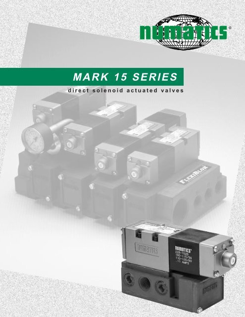
MARK 15 SERIES<br />
direct solenoid actuated valves<br />
®
MARK 15<br />
M a r k 1 5 d i r e c t s o l e n o i d a c t u a t e d v a l v e s<br />
T E C H N I C A L D A T A . . . . . . . . . . . . . . . . . . . . . . . . . . . . . . . . . . . . . . . . . . . . . . . . . . . 3<br />
V A L V E M O D E L S E L E C T I O N . . . . . . . . . . . . . . . . . . . . . . . . . . . . . . . . . . . . . . . 4<br />
V A L V E / B A S E D I M E N S I O N S . . . . . . . . . . . . . . . . . . . . . . . . . . . . . . . . . . . . . . . 5<br />
F L E X I B L O K M A N I F O L D S . . . . . . . . . . . . . . . . . . . . . . . . . . . . . . . . . . . . . . 6–7<br />
S A N D W I C H P R E S S U R E R E G U L A T O R S . . . . . . . . . . . . . . . . . . . . . 8–11<br />
R E G U L A T O R K I T S . . . . . . . . . . . . . . . . . . . . . . . . . . . . . . . . . . . . . . . . . . . . . . . . . . 11<br />
M A N I F O L D A C C E S S O R Y K I T S . . . . . . . . . . . . . . . . . . . . . . . . . . . . . . . . . . 12<br />
B A S E A S S E M B L Y K I T S . . . . . . . . . . . . . . . . . . . . . . . . . . . . . . . . . . . . . . . . . . . . 13<br />
F L E X I B L O K M A N I F O L D K I T S . . . . . . . . . . . . . . . . . . . . . . . . . . . . . . . . . . 13<br />
V A L V E S E R V I C E K I T S . . . . . . . . . . . . . . . . . . . . . . . . . . . . . . . . . . . . . . . . . . . . . 14<br />
S O L E N O I D A S S E M B L Y K I T S . . . . . . . . . . . . . . . . . . . . . . . . . . . . . . . . . . . . . 15<br />
Die cast aluminum alloy<br />
multi–purpose construction<br />
Time–proven lapped spool<br />
and sleeve assembly<br />
Plug–in direct solenoid<br />
provides fast response<br />
Valve unit to base<br />
integral plug<br />
MARK 15 FEATURES:<br />
Mark 15 valves have a plug–<br />
in base or manifold, a plug–in<br />
solenoid, and an optional<br />
speed control sandwich. The<br />
unit to base electrical plug<br />
permits instant valve unit<br />
replacement without disconnecting<br />
piping or wiring.<br />
Pilot light indicates when<br />
power is supplied to solenoid<br />
Flush non–locking<br />
manual override<br />
High flow capacity<br />
in a compact design
M a r k 1 5 v a l v e s<br />
• direct solenoid actuated<br />
• plug–in solenoid with indicator light<br />
• multi–purpose<br />
• 5–ported, 4–way, 2 and 3 position<br />
• lapped spool and sleeve assembly<br />
• Cv to 1.5<br />
• 1/4 and 3/8 NPTF or G Tap<br />
• for unlubricated or lubricated service<br />
• integral regulators available<br />
• integral speed control available<br />
• modular building block system<br />
• NEMA 4<br />
®<br />
T e c h n i c a l d a t a<br />
Valve Data NPTF<br />
G tap<br />
O p e r a t i n g d a t a<br />
All solenoids are continuous duty rated.<br />
Time to<br />
Energize<br />
in Seconds<br />
Time to<br />
De–Energize<br />
in Seconds<br />
12 VDC 24 VDC<br />
24 V<br />
AC<br />
50 Hz.<br />
24 V<br />
AC<br />
60 Hz.<br />
115 V<br />
AC<br />
50 Hz.<br />
M A R K 15<br />
Cv: 1/4 NPTF = 1.4 3/8 NPTF = 1.5 1/4 G Tap = 1.4 3/8 G Tap = 1.5<br />
Flow Capacity: upstream pressure to atmosphere 65 SCFM @ 80 PSIG 69 SCFM @ 80 PSIG 1379 Nl/m 1477 Nl/m<br />
6 Bar upstream/5 Bar downstream<br />
Operating Pressure Range: 28” Hg. Vacuum to 150 PSIG Vacuum to 10 Bar<br />
Temperature Range: –10°F to +115°F ambient –23°C to +46°C ambient<br />
120 V<br />
AC<br />
60 Hz.<br />
230 V<br />
AC<br />
50 Hz.<br />
240 V<br />
AC<br />
60 Hz.<br />
Power (Watts) 6.0 6.0 ––––– ––––– ––––– ––––– ––––– –––––<br />
Holding Current (Amps.) 0.50 0.250 0.59 0.42 0.11 0.09 0.07 0.05<br />
Inrush Current (Amps.) N/A N/A 2.85 2.53 0.63 0.58 0.31 0.29<br />
2–Position, Single, Spring Return 0.038 0.034 0.010 0.010 0.010 0.010 0.010 0.010<br />
2–Position, Double, Detented 0.035 0.035 0.010 0.010 0.010 0.010 0.010 0.010<br />
3–Position, Spring Centered 0.040 0.040 0.010 0.010 0.010 0.010 0.010 0.010<br />
2–Position, Single, Spring Return 0.016 0.011 0.015 0.015 0.015 0.015 0.015 0.015<br />
2–Position, Double, Detented N/A N/A N/A N/A N/A N/A N/A N/A<br />
3–Position, Spring Centered 0.010 0.010 0.012 0.012 0.012 0.012 0.012 0.012<br />
MK15-3<br />
MARK 15
MARK 15<br />
M a r k 1 5 m o d e l s e l e c t i o n t a b l e (standard valve/mounting combinations)<br />
Valve<br />
Function<br />
UNIT ONLY<br />
152SA400K UNIT ONLY (AC)<br />
152SA400M 152SA400K (DC)<br />
(2)(4)<br />
B A<br />
EB P EA<br />
(3) (1) (5)<br />
UNIT ONLY<br />
152SS400K UNIT ONLY (AC)<br />
152SS400M 152SS400K (DC)<br />
(2)(4)<br />
B A<br />
EB P EA<br />
(3) (1) (5)<br />
A<br />
(14)<br />
A<br />
(14)<br />
UNIT ONLY<br />
152SS500K UNIT ONLY(AC)<br />
152SS500M 152SS500K(DC)<br />
(2)(4)<br />
B A<br />
EB P EA<br />
(3) (1) (5)<br />
A<br />
(14)<br />
UNIT ONLY<br />
152SS600K UNIT ONLY(AC)<br />
152SS600M 152SS600K(DC)<br />
(2)(4)<br />
B A<br />
EB P EA<br />
(3) (1) (5)<br />
A<br />
(14)<br />
Port<br />
Size<br />
NPTF<br />
1/4<br />
1/4<br />
3/8<br />
3/8<br />
1/4<br />
1/4<br />
3/8<br />
3/8<br />
1/4<br />
1/4<br />
3/8<br />
3/8<br />
1/4<br />
1/4<br />
3/8<br />
3/8<br />
AC<br />
or<br />
DC<br />
*<br />
Individual base with<br />
side ports and<br />
common exhaust<br />
without<br />
speed<br />
control<br />
with<br />
speed<br />
control<br />
Individual base with<br />
side ports and<br />
individual exhaust<br />
without<br />
speed<br />
control<br />
with<br />
speed<br />
control<br />
FlexiBlok manifold,<br />
with side & bottom<br />
cylinder ports<br />
without<br />
speed<br />
control<br />
with<br />
speed<br />
control<br />
AC 152SA431K 152SA435K 152SA43AK 152SA43CK 152SA415K 152SA425K<br />
DC 152SA431M 152SA435M 152SA43AM 152SA43CM 152SA415M 152SA425M<br />
AC 153SA431K 153SA435K 153SA43AK 153SA43CK 153SA415K 153SA425K<br />
DC 153SA431M 153SA435M 153SA43AM 153SA43CM 153SA415M 153SA425M<br />
AC 152SS431K 152SS435K 152SS43AK 152SS43CK 152SS415K 152SS425K<br />
DC 152SS431M 152SS435M 152SS43AM 152SS43CM 152SS415M 152SS425M<br />
AC 153SS431K 153SS435K 153SS43AK 153SS43CK 153SS415K 153SS425K<br />
DC 153SS431M 153SS435M 153SS43AM 153SS43CM 153SS415M 153SS425M<br />
AC 152SS531K 152SS535K 152SS53AK 152SS53CK 152SS515K 152SS525K<br />
DC 152SS531M 152SS535M 152SS53AM 152SS53CM 152SS515M 152SS525M<br />
AC 153SS531K 153SS535K 153SS53AK 153SS53CK 153SS515K 153SS525K<br />
DC 153SS531M 153SS535M 153SS53AM 153SS53CM 153SS515M 153SS525M<br />
AC 152SS631K 152SS635K 152SS63AK 152SS63CK 152SS615K 152SS625K<br />
DC 152SS631M 152SS635M 152SS63AM 152SS63CM 152SS615M 152SS625M<br />
AC 153SS631K 153SS635K 153SS63AK 153SS63CK 153SS615K 153SS625K<br />
DC 153SS631M 153SS635M 153SS63AM 153SS63CM 153SS615M 153SS625M<br />
* Specify volts and Hz. after the model number.<br />
G tap options: For G tap ports, add a “G” to the model number. EXAMPLE: 153SS431MG<br />
DIN solenoid options: Replace “K” with “6” for DIN AC plug–in with light. For DIN DC plug–in w/out light replace “M” with “4” .<br />
EXAMPLES: DIN AC w/LIGHT: 153SS4316 DIN DC: 153SS4314 153224314 (for plug assemblies, see page MK15–15)
M a r k 1 5 v a l v e a n d b a s e d i m e n s i o n s<br />
152SA4 single direct solenoid actuated valve<br />
152SS4, 5, 6 double direct solenoid actuated valve<br />
Base 1/4 or 3/8 NPTF or G tap side ports<br />
1/2 NPTF conduit port connection<br />
3/8 NPTF common exhaust port<br />
Dimensions<br />
A<br />
B<br />
C<br />
D<br />
E<br />
F<br />
G<br />
H<br />
I<br />
J<br />
K AC<br />
K DC<br />
L AC<br />
L DC<br />
M AC<br />
M DC<br />
N<br />
O<br />
P<br />
Q<br />
R<br />
S<br />
T<br />
U<br />
V<br />
W<br />
X<br />
Y<br />
1.72<br />
(43.7)<br />
0.78<br />
(19.8)<br />
0.31<br />
(7.9)<br />
0.84<br />
(21.3)<br />
0.47<br />
(11.9)<br />
0.72<br />
(18.3)<br />
0.20<br />
(5.2)<br />
0.88<br />
(22.4)<br />
1.75<br />
(44.4)<br />
3.25<br />
(82.5)<br />
4.22<br />
(107)<br />
4.95<br />
(126)<br />
6.13<br />
(156)<br />
6.86<br />
(174)<br />
8.44<br />
(214)<br />
9.90<br />
(251)<br />
1.76<br />
(44.7)<br />
0.91<br />
(23)<br />
0.06<br />
(1.6)<br />
2.16<br />
(54.8)<br />
1.56<br />
(39.6)<br />
2.47<br />
(62.7)<br />
3.30<br />
(83.8)<br />
1.00<br />
(25.4)<br />
5.11<br />
(130)<br />
0.37<br />
(9.5)<br />
0.31<br />
(7.9)<br />
0.78<br />
(19.8)<br />
O E<br />
dimensions = inches<br />
(in parenthesis) = mm<br />
N<br />
Q<br />
P<br />
H<br />
3/8 NPTF<br />
Common<br />
Exhaust<br />
Optional Bottom<br />
Port Locations (5)<br />
1/4 or 3/8 NPTF or G tap<br />
E<br />
D<br />
G<br />
R<br />
D<br />
W<br />
W<br />
B<br />
J<br />
M<br />
A<br />
C<br />
U U<br />
V<br />
U U<br />
Y<br />
I<br />
X<br />
L<br />
M A R K 15<br />
K<br />
1/2 NPTF<br />
conduit port<br />
connection<br />
F<br />
E<br />
S<br />
H<br />
T<br />
MARK 15
MARK 15<br />
M a r k 1 5 F l e x i B l o k m a n i f o l d s<br />
stackable manifold mounting<br />
single supply and 2 common exhaust galleries<br />
end plate tapped, both ends<br />
H o w t o o r d e r<br />
List in order, left to right, facing cylinder ports A & B: (example)<br />
Assembly kit* AK151–4<br />
Pipe Plug: 129–102 in P gallery<br />
Station 1 153SA416K 120/60<br />
Blocking Disc 124–141 in P gallery<br />
Station 2 152SA400K 120/60<br />
153RT118J016N Regulator<br />
Blocking Disc 124–141 in P gallery<br />
Station 3 152SA400K 120/60<br />
153RT11BJ Regulator<br />
Station 4 153SA415K 120/60<br />
ASSEMBLED<br />
*<br />
AK151–<br />
No. of<br />
Stations<br />
Port<br />
Type<br />
Blank = NPTF<br />
G = G Tap Galleries and Metric Conduit<br />
C = G Tap Galleries and NPTF Conduit<br />
Assembly kits are for factory assembled units only. Kits consist of end plates, and screw assemblies; and also include assembly and testing of the entire FlexiBlok manifold for proper operation.<br />
Due to flow, wiring, and practical assembly limitations, a maximum of 12 stations per assembly is recommended.<br />
F l e x i B l o k D i a g r a m<br />
Sample diagram with regulators<br />
Mark 15 3–pressure selector FlexiBlok with output valve and separate 4–way (3/8 NPTF)<br />
EA<br />
P<br />
EB<br />
A<br />
FlexiBlok No. 16<br />
auxiliary inlet<br />
Output<br />
153SA416K<br />
B<br />
A<br />
B<br />
EA<br />
P<br />
EB<br />
XP XB<br />
FlexiBlok No. 18<br />
alternate outlet & auxiliary inlet<br />
+ jumper plate on A end<br />
Selector<br />
152SA400K<br />
153RT118J016N<br />
A<br />
R<br />
EA<br />
P<br />
EB<br />
XP XB<br />
B<br />
A B<br />
A B<br />
FlexiBlok No. 1B<br />
alternate outlet<br />
Selector<br />
152SA400K<br />
153RT11BJ<br />
A<br />
B<br />
EA<br />
P<br />
EB<br />
FlexiBlok No. 15<br />
side and bottom<br />
cylinder ports<br />
Standard<br />
4–Way<br />
153SS415K<br />
STATION 1 STATION 2 STATION 3 STATION 4<br />
Blocking discs must be installed in “P” gallery, as shown.<br />
A<br />
B<br />
A<br />
B<br />
EA<br />
P<br />
EB
M a r k 1 5 F l e x i B l o k a s s e m b l y d i m e n s i o n s<br />
FlexiBlok Manifold Block, Mark 15 valve shown with speed control<br />
1/4 and 3/8 NPTF or G tap side ports (A & B)<br />
1 1/4 NPTF conduit port connection<br />
Dimensions<br />
9.13<br />
A AC<br />
(232)<br />
9.86<br />
A DC<br />
(250)<br />
4.22<br />
B AC<br />
(107)<br />
4.95<br />
B DC<br />
(126)<br />
2.19<br />
C<br />
(56)<br />
6.00<br />
D<br />
(152)<br />
6.41<br />
E AC<br />
(163)<br />
7.14<br />
E DC<br />
(181)<br />
7.12<br />
F<br />
(181)<br />
5.11<br />
(130)<br />
H 4.29<br />
(109)<br />
I 0.53<br />
(13.5)<br />
J 1.12<br />
(28.4)<br />
K 3.54<br />
(89.9)<br />
L 4.36<br />
(110)<br />
M 0.42<br />
(10.7)<br />
N 1.16<br />
(29.5)<br />
O 1.06<br />
(26.9)<br />
P 1.25<br />
(31.7)<br />
Q 2.31<br />
(58.7)<br />
R 2.62<br />
(66.5)<br />
S 0.12<br />
(3.0)<br />
T 1.19<br />
(30.2)<br />
U 3.00<br />
(7.62)<br />
V 1.91<br />
(48.5)<br />
W 0.34<br />
(8.6)<br />
X 0.90<br />
(23.1)<br />
Y 0.67<br />
(17)<br />
Z 0.90<br />
(23.1)<br />
AA 0.15<br />
(4.1)<br />
BB 0.74<br />
(18.8)<br />
CC 0.44<br />
(11.1)<br />
DD 0.72<br />
(18.3)<br />
G<br />
H<br />
I<br />
1/4 or 3/8<br />
NPTF<br />
or G tap<br />
ports<br />
M<br />
dimensions = inches<br />
(in parenthesis) = mm<br />
N<br />
P<br />
Q<br />
Q<br />
O<br />
J<br />
K<br />
L<br />
R<br />
1/2 NPTF<br />
ports (6)<br />
Y<br />
Z<br />
AA<br />
1/4 or 3/8 NPTF<br />
(ports A and B)<br />
B<br />
N<br />
M<br />
DD<br />
C<br />
V<br />
E<br />
T T<br />
M A R K 15<br />
A<br />
W<br />
CC<br />
D<br />
F<br />
U<br />
1/4 or 3/8 NPTF<br />
(optional)<br />
X<br />
J<br />
S<br />
1 1/4 NPTF<br />
conduit port<br />
connection<br />
(both ends)<br />
BB<br />
MARK 15
MARK 15<br />
M a r k 1 5<br />
s a n d w i c h p r e s s u r e r e g u l a t o r s<br />
Types: RS / RD / RE / RT / RC / RQ<br />
When ordering a valve plus regulator mounted on a base or manifold,<br />
list the valve unit only model number and include the mounting<br />
requirements only with the regulator. Specify “Assembled.”<br />
Examples:<br />
TYPE RS TYPE RD<br />
Valve: 152SA400K 120/60 152SA400K 120/60<br />
Regulator: 153RS115J 153RD115J<br />
ASSEMBLED ASSEMBLED<br />
T Y P E<br />
RS<br />
T Y P E<br />
RE<br />
P<br />
P<br />
SUPPLY<br />
T Y P E<br />
RC<br />
Type RC is is Non–Relieving:<br />
Non-Relieving:<br />
traps downstream pressure<br />
if upstream pressure is exhausted.<br />
Recommended<br />
for accurate cylinder positioning<br />
when used with wih<br />
valve model model152SS500K.<br />
152SS500K.<br />
B A<br />
P<br />
SUPPLY<br />
CHECK<br />
ASSEMBLY<br />
Single<br />
pressure from<br />
a single<br />
supply.<br />
Dual pressure<br />
from a single<br />
supply.<br />
EB EA<br />
P<br />
SUPPLY<br />
External outlet<br />
regulator used with<br />
jumper plate for<br />
single or dual<br />
pressure.<br />
Two–pressure<br />
selector used for<br />
multi–pressure<br />
applications.<br />
CHECK<br />
ASSEMBLY<br />
EB EA<br />
P<br />
SUPPLY<br />
T Y P E<br />
RQ<br />
T Y P E<br />
RD<br />
Type RQ is Relieving:<br />
exhausts<br />
exhausts<br />
pressure<br />
pressure<br />
in<br />
in<br />
cylinder<br />
cylinder<br />
cylinder<br />
if<br />
if<br />
upstream pressure is exhausted.<br />
Recommended upstream pressure for accurate is exhausted.<br />
cylinder Recommended positioning for accurate when used<br />
with cylinder valve positioning model 152SS500K.<br />
when used<br />
wih valve model152SS500K.<br />
EB P<br />
P<br />
SUPPLY<br />
T Y P E<br />
RT
M a r k 1 5 r e g u l a t o r m o d e l s e l e c t i o n (Standard regulator/mounting combinations)<br />
Regulator<br />
Function<br />
Type RS<br />
UNIT ONLY<br />
152RS_00J<br />
Type RS*<br />
no receptacle<br />
(used with<br />
valve + speed control<br />
+ mounting)<br />
Type RD<br />
UNIT ONLY<br />
152RD_00J<br />
Type RE**<br />
no receptacle<br />
UNIT ONLY<br />
152RE_00O<br />
Type RT<br />
UNIT ONLY<br />
152RT_00J<br />
Type RC<br />
UNIT ONLY<br />
152RC_00J<br />
Type RQ<br />
UNIT ONLY<br />
152RQ_00J<br />
Port<br />
Size<br />
NPTF<br />
1/4<br />
3/8<br />
1/4<br />
3/8<br />
1/4<br />
3/8<br />
1/4<br />
3/8<br />
1/4<br />
3/8<br />
1/4<br />
3/8<br />
1/4<br />
3/8<br />
M A R K 15<br />
152RS131J 152RS331J 152RS431J 152RS115J 152RS315J 152RS415J<br />
153RS131J 153RS331J 153RS431J 153RS115J 153RS315J 153RS415J<br />
152RS131O 152RS331O 152RS431O 152RS115O 152RS315O 152RS415O<br />
153RS131O 153RS331O 153RS431O 153RS115O 153RS315O 153RS415O<br />
152RD131J 152RD331J 152RD431J 152RD115J 152RD315J 152RD415J<br />
153RD131J 153RD331J 153RD431J 153RD115J 153RD315J 153RD415J<br />
152RE131O 152RE331O 152RE431O 152RE115O 152RE315O 152RE415O<br />
153RE131O 153RE331O 153RE431O 153RE115O 153RE315O 153RE415O<br />
152RT131J 152RT331J 152RT431J 152RT115J 152RT315J 152RT415J<br />
153RT131J 153RT331J 153RT431J 153RT115J 153RT315J 153RT415J<br />
152RC131J 152RC331J 152RC431J 152RC115J 152RC315J 152RC415J<br />
153RC131J 153RC331J 153RC431J 153RC115J 153RC315J 153RC415J<br />
152RQ131J 152RQ331J 152RQ431J 152RQ115J 152RQ315J 152RQ415J<br />
153RQ131J 153RQ331J 153RQ431J 153RQ115J 153RQ315J 153RQ415J<br />
G tap options: For G tap ports, add a “G” to the model number. EXAMPLE: 153RD115JG<br />
* Speed control can only be used with TYPE RS. These model numbers indicate regulators with no receptacle. The plug–in receptacle is installed<br />
in the speed control body. For more information, see page 11.<br />
** Type RE includes jumper plate kit #229–620<br />
Individual base, side ports,<br />
common exhaust with plug–in receptacle<br />
FlexiBlok manifold, side and bottom<br />
cylinder ports with plug–in receptacle<br />
10–130 PSIG 3–30 PSIG 5–60 PSIG 10–130 PSIG 3–30 PSIG 5–60 PSIG<br />
MARK 15
MARK 15<br />
M a r k 1 5 s a n d w i c h p r e s s u r e r e g u l a t o r d i m e n s i o n s<br />
C<br />
D<br />
E<br />
Dimensions<br />
B<br />
F<br />
A B C D E F G<br />
3.87 1.62 5.70 3.15 1.73 1.94 2.80<br />
(98) (41) (144) (80) (44) (49) (71)<br />
H I J K L M N<br />
3.025 1.66 5.68 7.02 7.33 10.92 0.657<br />
(76.8) (42.2) (144) (178) (186) (277) (16.7)<br />
13 6 14<br />
N<br />
G<br />
A<br />
15<br />
1 2 3<br />
dimensions = inches<br />
(in parenthesis) = mm<br />
D u a l c h e c k a s s e m b l y k i t s: RC 239–533<br />
(For converting RD into RC or RQ.)<br />
RQ 239–537<br />
9<br />
11 12<br />
4 5 6 7 8<br />
H<br />
10<br />
I<br />
M<br />
DET.<br />
NO.<br />
L<br />
K<br />
NO.<br />
REQ’D PART NAME PART NO.<br />
1 *2 Gauge See chart on page 11<br />
2 *2 90 Tube Fitting 134–289<br />
3 *2 Straight Fitting 134–293<br />
4 1 Plug Receptacle Assembly 230–257<br />
5 1 Screw 127–342<br />
6 ** Gasket to regulator 113–272<br />
7 ~8 Screw 127–235<br />
8 *2 Reg. Assembly (not sold separately)<br />
9 1 Nameplate 122–551<br />
10 1 Regulator Block: RS 125–311<br />
RD, RC, RQ 125–312<br />
RT 125–313<br />
RE 125–316<br />
11 1 Gasket body to base 113–264<br />
12 3 Studs 127–304<br />
13 2 Check Assembly (not sold separately)<br />
14 8 Hi–Collar Lockwasher<br />
(RC, RQ only)<br />
128–144<br />
15 8 Screw (RC, RQ only) 127–227<br />
* RS Models require (1).<br />
** (1) for RS; (2) for RD RE RT; (4) for RC RQ.<br />
~ RS Models require (4)<br />
J
M a r k 1 5 v a l v e / s p e e d c o n t r o l / r e g u l a t o r p l u g – i n a s s e m b l y<br />
Screw<br />
Assembly<br />
#127–295<br />
(3) Studs<br />
#127–304<br />
R e g u l a t o r s e r v i c e k i t 229–640*<br />
1 2 3 4 5 6<br />
7<br />
3–wire plug assembly<br />
#230–233<br />
(SA4 model only)<br />
5– Wire Plug<br />
Receptacle<br />
Assembly<br />
#230–229<br />
M a r k 1 5 r e g u l a t o r k i t s & s e r v i c e p a r t s<br />
8 9 10<br />
J u m p e r p l a t e k i t 229–644<br />
(includes gasket #113–434 and screws #127–235)<br />
11<br />
12<br />
13<br />
14<br />
NOT TO SCALE<br />
NOTE:<br />
models SS4, 5, & 6<br />
use a 5–wire plug<br />
assembly #230–234<br />
DET.<br />
NO.<br />
EXAMPLE<br />
152SA401K<br />
Single solenoid valve unit +<br />
speed control sandwich<br />
with 5–wire plug receptacle<br />
and extra long screws<br />
153RS131O<br />
M A R K 15<br />
NO.<br />
PRESSURE RANGE PSIG<br />
REQ’D PART NAME<br />
3–30 5–60 10–130<br />
1 1 Regulator Assembly Not Sold Separately<br />
*2 1 Retainer 116–291 116–291 116–291<br />
*3 1 Spring 115–210 115–210 115–210<br />
*4 1 Poppet Assembly 221–121 221–121 221–121<br />
*5 1 Poppet Seat 124–142 124–142 124–142<br />
*6 1 Diaphragm Ass’y 213–285 213–285 213–285<br />
*7 1 Washer 116–292 116–292 116–292<br />
8 1 Bonnet Spring 115–211 115–212 115–213<br />
*9 1 Spring Guide 116–293 116–293 116–293<br />
10 1 Bonnet 125–314 125–314 125–314<br />
11 1 Locknut 128–177 128–177 128–177<br />
12 1 Pressure Label 122–508 122–509 122–510<br />
13 1 Knob Assembly 213–284 213–284 213–284<br />
14 Regulator Gauges 214–116 214–117 214–103<br />
(with PSIG of . . .) (0–60) (0–100) (0–160)<br />
Regulator Unit Kits (includes<br />
regulator assembly, gaskets, screws)<br />
229–641 229–642 229–643<br />
* Indicates all parts included in regulator service kit.<br />
3/8 NPTF single pressure regulator<br />
(10–130 PSIG) with no receptacle<br />
mounted on an individual base<br />
with side ports and common exhaust<br />
EXAMPLE ORDER:<br />
Valve: 152SA401K 120/60<br />
Regulator: 153RS131O<br />
ASSEMBLED<br />
RE t o p j u m p e r p l a t e k i t 229–620<br />
(includes gasket #113–264 and screws #127–235)<br />
MARK 15
MARK 15<br />
M a r k 1 5 m a n i f o l d a c c e s s o r y k i t s<br />
E n d p l a t e k i t s NPTF 229–621 G Tap 229–993 G Tap 239–530<br />
B l a n k s t a t i o n p l a t e 229–620<br />
(includes plate, gasket #113–264 and (3) screws #127–235)<br />
A d a p t o r k i t s w i t h e n d p l a t e s<br />
Mark 15 RIGHT* of Mark 8 229–695<br />
includes Kit #229–694 (adaptor, screws, seals) + Mark 15 & 8 end plates<br />
Mark 15 LEFT* of Mark 8 229–693<br />
includes Kit #229–692 (adaptor, screws, seals) + Mark 15 & 8 end plates<br />
Mark 15 RIGHT* of Mark 55 Compact 229–858<br />
includes Kit #229–857 (adaptor, screws, seals) + Mark 15 & 55 end plates<br />
Mark 15 LEFT* of Mark 55 Compact 229–860<br />
includes Kit #229–859 (adaptor, screws, seals) + Mark 15 & 55 end plates<br />
Mark 15 RIGHT* of Mark Plus 6 239–766<br />
includes Kit #239–709 (adaptor, screws, seals) + Mark 15 & 6 end plates<br />
Mark 15 LEFT* of Mark Plus 6 239–767<br />
includes Kit #239–710 (adaptor, screws, seals) + Mark 15 & 6 end plates<br />
* left / right when viewed from the cylinder ports of assembly<br />
S p e e d c o n t r o l k i t 229–664<br />
w i t h p l u g, Cv = 2.0<br />
1<br />
A<br />
B<br />
2 3<br />
5<br />
4<br />
C<br />
Mounts between valve and base.<br />
D<br />
6<br />
NO.<br />
REQ’D<br />
G galleries with metric conduit G galleries with NPTF conduit<br />
PART NAME<br />
NPTF<br />
PART NUMBER<br />
G Tap<br />
w/metric<br />
conduit<br />
G Tap<br />
w/NPTF<br />
conduit<br />
1 Seal 126–121 126–121 126–121<br />
1 Right End Plate 104–217 104–287 104–468<br />
1 Nameplate 122–199 122–199 122–199<br />
1 Left End Plate 104–218 104–288 104–469<br />
2 Screws 127–152 127–152 127–152<br />
3 Seal 126–209 126–209 126–209<br />
B l o c k i n g d i s c 124–141<br />
Mark 15<br />
left end plate<br />
O – Ring<br />
(not included)<br />
Mark 15 to<br />
Mark 55 Compact<br />
adaptor<br />
Mark 55 Compact<br />
right end plate<br />
B A<br />
S p e e d c o n t r o l k i t 229–622<br />
Cv = 2.0<br />
DET.<br />
NO.<br />
NO.<br />
REQ’D PART NAME<br />
PART NO.<br />
*1 1 Gasket 113–264<br />
*2 3 Screw Assembly 127–295<br />
*3 1 Speed Control Ass’y<br />
not sold separately<br />
–––<br />
**4 1 Receptacle Ass’y 230–229<br />
**5 1 Receptacle Screw 127–169<br />
*6 2 Needle Assembly 213–180<br />
* indicates parts included in kit<br />
** included in 229–664 kit only<br />
Dimensions<br />
Blocking Disc<br />
A B C D<br />
inches 2.94 2.69 1.69 0.75<br />
(mm) (74.7) (68) (43) (19)
M a r k 1 5 b a s e a s s e m b l y k i t s<br />
1<br />
2<br />
3<br />
4<br />
5<br />
6<br />
7<br />
DET.<br />
NO.<br />
NO.<br />
REQ’D<br />
PART NAME<br />
M A R K 15<br />
PART NO.<br />
*1 1 Base — not sold separately<br />
*2 2 Screw 127–176<br />
*3 1 Washer 128–162<br />
*4 1 Screw 127–342<br />
*5 1 Receptacle Assembly<br />
Plug–in units only<br />
230–229<br />
*6 1 Conduit Cover Ass’y 205–302<br />
*7 ** Plug: 1/4 NPTF 129–101<br />
3/8 NPTF 129–102<br />
G 1/4 129–161<br />
G 3/8 129–163<br />
* indicates parts included in kit.<br />
** Not used on 3A, 3C; # plugs vary – Consult factory.<br />
1/4 NPTF 3/8 NPTF G 1/4 G 3/8<br />
Base Exhaust Plug–In No Plug Plug–In No Plug Plug–In No Plug Plug–In No Plug<br />
31 & 35: Side ports only common 203–353 203–349 203–361 203–357 203–561 203–659 203–557 203–660<br />
32 & 36: Side & bottom ports common 203–354 203–350 203–362 203–358 203–663 203–661 203–664 203–662<br />
3A & 3C: Side ports only individual 203–351 203–347 203–359 203–355 203–611 203–665 203–612 203–645<br />
3B & 3D: Side & bottom ports individual 203–352 203–348 203–360 203–356 203–668 203–667 203–670 203–669<br />
M a r k 1 5 F l e x i b l o k m a n i f o l d k i t s<br />
1<br />
2<br />
3<br />
4<br />
5<br />
6<br />
7<br />
8<br />
9<br />
10<br />
11<br />
12<br />
DET. NO.<br />
NO. REQ’D PART NAME<br />
PART NO.<br />
*1 1 Valve blok — not sold separately.<br />
*2 1 Seal 126–121<br />
*3 3 Seal 126–209<br />
*4 1 Seal (for “1B” & “18”) 126–202<br />
*5 2 Nut 128–103<br />
*6 2 Screw 127–176<br />
*7 1 Washer 128–162<br />
*8 1 Conduit Cover Ass’y 205–303<br />
*9 1 Receptacle Assembly<br />
(Plug–in units only)<br />
230–229<br />
*10 1 Screw – receptacle 127–342<br />
*11 2 Screw 127–152<br />
*12 2 Plug: 1/4 NPTF 129–101<br />
3/8 NPTF 129–102<br />
G 1/4 129–161<br />
G 3/8 129–163<br />
* indicates parts included in kit.<br />
1/4 NPTF 3/8 NPTF G 1/4 G 3/8<br />
FlexiBlok Description Plug–In No Plug Plug–In No Plug Plug–In No Plug Plug–In No Plug<br />
#15: side & bottom cylinder ports 229–629 229–627 229–630 229–628 239–210 239–367 229–999 239–368<br />
#15: side & bottom cyl. ports w/bottom P port 229–632 229–631 229–634 229–633 239–371 239–369 239–372 239–370<br />
#16: auxiliary inlet 229–792 229–789 229–798 229–795 239–375 239–373 239–376 239–374<br />
#1B: alternate outlet 229–793 229–790 229–799 229–796 239–383 239–381 239–384 239–382<br />
#18: alternate outlet & auxiliary inlet 229–794 229–791 229–800 229–797 239–379 239–377 239–380 239–378<br />
MARK 15
MARK 15<br />
M a r k 1 5 v a l v e s e r v i c e k i t s a n d p a r t s<br />
Kit No. MK15–K1* (for models 152SA4, 153SA4) Kit No. MK15–K2* (for models 152SS4, 153SS4)<br />
1<br />
2 3 4 5 6 7 8 9 10 11<br />
12 13 14 15 16<br />
DET.<br />
NO.<br />
NO.<br />
REQ’D.<br />
PART NAME PART NO.<br />
1 1 End Plate Assembly 204–215<br />
*2 1 Spring Retainer 116–286<br />
*3 1 Spring 115–214<br />
4 1 Nameplate 122–941<br />
5 1 Sleeve Assembly with seals 209–246<br />
*6 6 Seal 126–202<br />
7 3 Screw 127–294<br />
8 1 Electrical Receptacle 125–309<br />
*9 2 Gasket Solenoid to Valve 113–268<br />
*10 1 Detent Body 110–113<br />
11 1 Solenoid Capsule Assembly See Chart<br />
12 1 Valve Body (Not Sold Separately)<br />
*13 1 Gasket (Body to Base) 113–264<br />
14 1 Screw 127–169<br />
15 1 3–Wire Plug Assembly 230–233<br />
*16 1 Gasket Solenoid to end cap 113–267<br />
1 2 5 4 5 6 7 8 9<br />
10 11 12 13 14<br />
DET.<br />
NO.<br />
NO.<br />
REQ’D.<br />
PART NAME PART NO.<br />
*1 1 Spacer 116–285<br />
2 1 Nameplate 122–941<br />
3 1 Sleeve Assembly with Seals 209–247<br />
*4 6 Seal 126–202<br />
5 3 Screw 127–294<br />
6 2 Electrical Receptacle 125–309<br />
*7 2 Gasket Solenoid to Valve 113–268<br />
*8 1 Detent Assembly 210–116<br />
9 2 Solenoid Capsule Assembly See Chart<br />
10 1 Valve Body (Not Sold Separately)<br />
*11 1 Gasket (Body to Base) 113–264<br />
12 1 Screw 127–169<br />
13 1 5–Wire Plug Assembly 230–234<br />
*14 2 Gasket (Solenoid to end cap) 113–267<br />
Kit No. MK15–K3* (for models 152SS5, 153SS5) Kit No. MK15–K3* (for models 152SS6, 153SS6)<br />
1 2 5 4 5 6 7 8 9<br />
11<br />
12 13 14 15 16<br />
DET.<br />
NO.<br />
NO.<br />
REQ’D.<br />
PART NAME PART NO.<br />
*1 2 Spring 115–204<br />
2 2 Electrical Receptacle 125–309<br />
3 1 Nameplate 122–941<br />
4 1 Sleeve Assembly with Seals 209–248<br />
*5 6 Seals 126–202<br />
6 3 Screw Assembly 127–294<br />
*7 2 Spring Retainer 116–287<br />
*8 2 Gasket (Solenoid to Valve) 113–268<br />
*9 1 Spacer 116–288<br />
10 2 Solenoid Capsule Assembly See Chart<br />
*11 1 Spacer 116–289<br />
12 1 Valve Body (Not Sold Separately)<br />
*13 1 Gasket (Body to Base) 113–264<br />
14 1 Screw 127–169<br />
15 1 5–Wire Plug Assembly 230–234<br />
*16 2 Gasket (Solenoid to end cap) 113–267<br />
10<br />
1 2 5 4 5 6 7 8 9<br />
11<br />
12 13 14 15 16<br />
DET.<br />
NO.<br />
NO.<br />
REQ’D.<br />
PART NAME PART NO.<br />
*1 2 Spring 115–204<br />
2 2 Electrical Receptacle 125–309<br />
3 1 Nameplate 122–941<br />
4 1 Sleeve Assembly with Seals 209–249<br />
*5 6 Seals 126–202<br />
6 3 Screw Assembly 127–294<br />
*7 2 Spring Retainer 116–287<br />
*8 2 Gasket (Solenoid to Valve) 113–268<br />
*9 1 Spacer 116–288<br />
10 2 Solenoid Capsule Assembly See Chart<br />
*11 1 Spacer 116–289<br />
12 1 Valve Body (Not Sold Separately)<br />
*13 1 Gasket (Body to Base) 113–264<br />
14 1 Screw 127–169<br />
15 1 5–Wire Plug Assembly 230–234<br />
*16 2 Gasket (Solenoid to end cap) 113–267<br />
* Indicates parts included in service kit. Spool & sleeve assemblies are precision matched sets; assemblies include (6) 126–202 seals; spools are not interchangeable..<br />
10
M a r k 1 5 s o l e n o i d a s s e m b l i e s<br />
C o m p l e t e s o l e n o i d c a p s u l e a s s e m b l i e s E n d c a p o n l y<br />
includes solenoid and end cap assemblyy VOLTAGE LIGHT OPTION<br />
+ screws and gaskets<br />
AC DC AC DC<br />
Override<br />
Type<br />
Flush<br />
non–locking l ki<br />
override<br />
Valve<br />
Function<br />
Plug–in<br />
Style<br />
100–115/50<br />
110–120/60<br />
M A R K 15<br />
200–230/50<br />
220–240/60 24/50–60 12 VDC 24 VDC 100–130V 200–260V 12VDC 24VDC NO LIGHT<br />
2 position Standard 237–325 237–326 237–426 226–800 226–801 204–217 204–218 204–491 204–492 204–216<br />
2 position DIN plug–in 237–337 237–338 ––– 226–509* 226–510* 204–217 204–218 N/A N/A 204–216<br />
with light 3 position Standard 237–331 237–332 237–425 226–804 226–805 204–220 204–221 204–495 204–496 204–219<br />
3 position DIN plug–in 237–343 237–344 ––– 226–515* 226–516* 204–220 204–221 N/A N/A 204–219<br />
Flush 2 position Standard 237–361 237–362 ––– ––– 226–902 204–226 204–227 ––– ––– 204–224<br />
locking<br />
w/light 3 position Standard 237–363 237–364 ––– ––– 236–213 204–228 204–229 ––– ––– 204–225<br />
Ext. rod 2 position Standard 237–365 237–366 237–612 ––– 226–906 204–238 204–239 ––– ––– 204–236<br />
locking<br />
w/light 3 position Standard 237–367 237–368 ––– ––– 226–553 204–240 204–241 ––– ––– 204–237<br />
S o l e n o i d o n l y<br />
no end cap;<br />
Standard 228–702 228–707 228–708 225–371 225–372 * DIN DC solenoids are not available with light.<br />
screws screws, gaskets are<br />
NOT included. DIN plug–in 228–694 228–695 228–696 225–265 225–266<br />
1<br />
Flush Locking Override with light<br />
(Add option “011B” to model no.)<br />
Example: 152SA400K011B<br />
Flush Non–Locking Override<br />
with light (Standard)<br />
Extended Knurled Rod<br />
Locking Override with light<br />
(Add option “011Z” to model no.)<br />
Example: 152SA400K011Z<br />
DET.<br />
NO.<br />
NO.<br />
REQ’D PART NAME<br />
PART NO.<br />
1 1 Gasket (sol. to valve) 113–268<br />
2 1 Solenoid see chart<br />
3 1 Light Assembly:<br />
100–115/50 230–235<br />
110–120/60 230–235<br />
200–230/50 230–236<br />
220–240/60 230–236<br />
12VDC 230–283<br />
24VDC 230–284<br />
4 1 O–Ring Seal 126–144<br />
5 1 Gasket (Sol. to end cap) 113–267<br />
6 1 Bumper:<br />
Black for 2–Position 114–134<br />
Red for 3–Position 114–133<br />
7 1 End Cap Assembly see chart<br />
8 2 Screw (cap to sol.) 127–297<br />
9 2 Screw (AC sol. to valve) 127–298<br />
Screw (DC sol. to valve) 127–302<br />
P l u g – in c o n n e c t o r a s s e m b l i e s S u p e r s t r u c t u r e p l u g c o n n e c t o r w i t h c o r d<br />
Per DIN Spec. No. 43650 Per DIN Spec. No. 43650<br />
Accepts cable dia. .310 – .410 For DIN plug–in solenoids wiring options 6 & 4 For DIN plug–in solenoids wiring options 6 & 4<br />
1.04<br />
(26.4)<br />
2 3 4<br />
5<br />
6 7<br />
8 9<br />
Part Name Part No. Part Name Part No.<br />
Grey (A) Plug. Ass’y. 230–369 1.06<br />
(26.8)<br />
Plug with 4’ Cord 230–213<br />
Black (B) Plug Ass’y. 230–370 Plug with 6’ Cord 230–215<br />
Plug with 24VDC Light 230–371<br />
Plug with 110VAC Light 230–372<br />
Plug with 220VAC Light 230–373<br />
Plug with 12VDC Light 230–385<br />
dimensions = inches<br />
(in parenthesis = mm)<br />
MARK 15


