IMO - 49 EJ/EJX (MODEL G) ELECTRIC ACTUATORS
IMO - 49 EJ/EJX (MODEL G) ELECTRIC ACTUATORS
IMO - 49 EJ/EJX (MODEL G) ELECTRIC ACTUATORS
You also want an ePaper? Increase the reach of your titles
YUMPU automatically turns print PDFs into web optimized ePapers that Google loves.
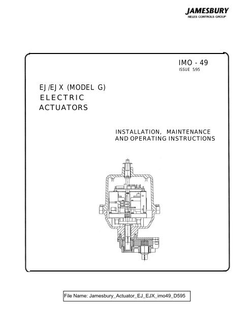
<strong>EJ</strong>/<strong>EJ</strong>X (<strong>MODEL</strong> G)<br />
<strong>ELECTRIC</strong><br />
<strong>ACTUATORS</strong><br />
<strong>IMO</strong> - <strong>49</strong><br />
ISSUE 5/95<br />
INSTALLATION, MAINTENANCE<br />
AND OPERATING INSTRUCTlONS
2<br />
Table of Contents<br />
I GENERAL ................................ 3<br />
1.1 Warning . . . . . . . . . . . . . . . . . . . . . . . . . . . . . . . . . . 3<br />
1.2 Operating Instructions . . . . . . . . . . . . . . . . . . . . . . . . . . . 3<br />
2 INSTALLATION ............................ 3<br />
2.1 General. . . . . . . . . . . . . . . . . . . . . . . . . . . . . . . . . . . 3<br />
2.2 Installation of Accessories . . . . . . . . . . . . . . . . . . . . . . . . . 4<br />
2.3 Installation of Heater Option (LK5060) . . . . . . . . . . . . . . . . . . 4<br />
2.4 Installation of the Auxiliary Board , . . . . . . . . . . . . . . . . . . . . . 4<br />
2.5 Installation of the Two Extra SPDT Limit Switches Option (EH5089) . . . 4<br />
3 MAINTENANCE ............................ 5<br />
3.1 General. . . . . . . . . . . . . . . . . . . . . . . . . . . . . . . . . . . 5<br />
4 CAM ADJUSTMENT INSTRUCTIONS ................ 5<br />
4.1 General . . . . . . . . . . . . . . . . . . . . . . . . . . . . . . . . . . 5<br />
4.2 Valve Open Position . . . . . . . . . . . . . . . . . . . . . . . . . . . 5<br />
4.3 Valve Closed Position . . . . . . . . . . . . . . . . . . . . . . . . . . . 5<br />
5 REPLACEMENT OF MOTOR CONTROL LIMIT SWITCH ..... 5<br />
6 MANUAL OVERRIDE INSTRUCTIONS ............... 6<br />
7 EXPLODED VIEWS AND PARTS LIST. ............... 7<br />
READ THESE INSTRUCTIONS FIRST!<br />
These instructions provide information about safe handling and operation of the valve<br />
If you require additional assistance, please contact the distributor or representative.<br />
The address and phone number are printed on the back cover.<br />
SAVE THESE INSTRUCTIONS!<br />
Subject to change without notice.
I GENERAL<br />
1.1 WARNING<br />
I. DISCONNECT POWER BEFORE REMOVING COVER.<br />
2. TO PREVENT IGNITION OF HAZARDOUS ATMOSPHERES,<br />
DISCONNECT SUPPLY CIRCUIT BEFORE OPENING UNIT.<br />
KEEP ASSEMBLY TIGHTLY CLOSED WHEN IN OPERATION.<br />
3. TO MAINTAIN THE HAZARDOUS LOCATION RATING OF<br />
<strong>EJ</strong>X <strong>ACTUATORS</strong>, IT IS ESSENTIALTHAT MATING SURFACES<br />
OF FLANGES BE PROTECTED FROM NICKS AND SCRATCHES<br />
WHILE DISASSEMBLED. UPON REASSEMBLY, THERE MUST BE<br />
NO DIRT OR PARTICLES ON THE MATING SURFACES OR<br />
FLANGES.<br />
4. BEFORE INSTALLING THE VALVE AND ACTUATOR, BE<br />
SURE THAT THE INDICATOR POINTER ON TOP OF THE<br />
ACTUATOR IS CORRECTLY INDICATING THE VALVES PO-<br />
SITION. FAILURE TO ASSEMBLE THESE PRODUCTS TO INDI-<br />
CATE CORRECT VALVE POSITION COULD RESULT IN<br />
PERSONAL INJURY.<br />
1.2 OPERATING INSTRUCTION<br />
Normal operating voltages for electric actuators: 115 VAC, 230<br />
VAC as specified on the actuator. Refer to Product Bulletin A120-2<br />
for torque output, duty cycle and operating speed. See wiring<br />
diagram for proper wiring. Operating temperature range is -40°F<br />
to +120°F however, below +40° F the heater option is required.<br />
MOUNTING INSTRUCTIONS<br />
I/4" - 2" A, AF & B Style Valves AMI-I<br />
l/4" - 2" CLINCHER@ Valves AMI-2<br />
I-l/2" - 2" A, AF, B Style Valves AMI-3<br />
l/4" - 2" HP/HT Valves AMI-5<br />
I/4" - 2" Series 5000 Valves AMI-8<br />
3" - 4" 5150, 3" - 4" 5300, 2" - 3" 6150<br />
2" - 3" 6300 AMI-9<br />
1/2" - 2" Series 4000 Valves AMI-10<br />
Butterfly Valves (See Valve <strong>IMO</strong>)<br />
To obtain copies of these, contact your nearest Neles-Jamesbury<br />
stocking distributor or write: Neles-Jamesbury, Inc., Box 15004,<br />
640 Lincoln Street, Worcester, Massachusetts 01615-0004, U.S.A.<br />
CAUTION<br />
2 INSTALLATION CAUTION<br />
2.1 General<br />
Mount these actuators by following actuator mounting instructions<br />
contained in the following AMI’s:<br />
WIRING OF THE <strong>EJ</strong>/<strong>EJ</strong>X (<strong>MODEL</strong> G) ACTUATOR<br />
WHENEVER AN ACTUATOR IS REMOVED FROM THE<br />
VALVE AND THEN REMOUNTED, THE LIMIT SWITCHES<br />
MUST BE READJUSTED. SEE ADJUSTMENT SECTION.<br />
WHEN SERVICING A VALVE/ACTUATOR ASSEMBLY, THE<br />
BEST PRACTICE IS TO REMOVE THE ENTIRE ASSEMBLY<br />
FROM SERVICE.<br />
BEFORE PERFORMING ANY MAINTENANCE TO THIS AC-<br />
TUATOR, DISCONNECT INCOMING POWER AND UN-<br />
PLUG THE CAPACITOR FROM THE BASIC BOARD.<br />
3
4<br />
2.2 INSTALLATION OF ACCESSORIES 2.4 INSTALLATION OF THE<br />
To remove the cover from the <strong>EJ</strong> actuators remove the indicator<br />
pointer and the cover hold down screws. On <strong>EJ</strong>X actuators only,<br />
the indicator pointer is part of the cover sub-assembly and is<br />
therefore not removed prior to removing the cover.<br />
When reinstalling the cover care must be taken not to allow the<br />
cover to cock in relation to the base. On all <strong>EJ</strong> actuators the cover<br />
gasket must be installed between the cover and base flanges before<br />
reinstalling the cover. Tighten one screw partially then another on<br />
the opposite side of the flange, repeating this procedure until all<br />
screws are partially tightened. Repeat this procedure to fully<br />
tighten screws. On the <strong>EJ</strong>X actuators replace the cover and cover<br />
hold down screws. Care must be taken during reassembly that no<br />
particles or dirt are on the mating surface of flanges.<br />
2.3 INSTALLATION OF THE<br />
Internal Heater<br />
HEATER OPTION (LK 5060)<br />
An internal heater with a thermoswitch is available for Neles-<br />
Jamesbury <strong>EJ</strong> and <strong>EJ</strong>X actuators. These heaters are recommended<br />
for use whenever an actuator is installed in areas where the<br />
temperatures will be below +4O°F (+4°C) in order to prevent<br />
condensation. Power requirement for standard heaters for <strong>EJ</strong> and<br />
<strong>EJ</strong>X actuators is 100 watts.<br />
I. Mount the thermoswitch to the Basic Board mounting bracket<br />
using the screws, nuts and lock washer provided in the linkage kit.<br />
2. Place the heater blanket around the motor(s).<br />
3. Route one lead wire through the conduit. Cut the second lead<br />
wire approximately 4" or long enough to reach one of the terminals<br />
on the thermoswitch. Assemble one of the connectors and insulator<br />
provided in the linkage kit to it and connect it to the thermoswitch.<br />
4. Assemble a connector and insulator to one end of the cut off<br />
lead wire.<br />
5. Connect the lead wire to the thermoswitch and route it through<br />
the conduit.<br />
6. Apply the label from the linkage kit to the outside of the cover.<br />
FIGURE I<br />
AUXILIARY BOARD<br />
To install the board simply snap the two stand-offs into the holes<br />
provided on the leg of the mounting bracket. Terminal #I (N.O.),<br />
#2 (Common), #3 (N.C.) for the open auxiliary switch. Terminal<br />
#4 (N.O.), #5 (Common), #6 (N.C.) for the close auxiliary switch.<br />
Terminals 7, 8 and 9 are not used.<br />
NELES-JAMESBURY<br />
300-0017-00<br />
AUXILIARY BOARD<br />
FIGURE 2<br />
2.5 INSTALLATION OF THE TWO EXTRA<br />
SPDT LIMIT SWITCH OPTION (EH5089):<br />
The linkage kit contains two pre-wired SPDT limit switch packages,<br />
wiring labels and the auxiliary board. Each limit switch package is<br />
made up of: a limit switch housing, a cam, a prewired 5 AMP limit<br />
switch with a female connector. Once the auxiliary board has been<br />
installed the two SPDT limit switches will plug into the auxiliary<br />
board connectors.<br />
The standard convention for installing limit<br />
switches in N-J products is: the lower switch will<br />
control or indicate the close position, and the upper<br />
switch will control or indicate the open position.<br />
To install a switch package onto the top of the existing motor<br />
control limit switches follow the steps as outlined below:<br />
I. Slide a fully assembled switch package over the cam/gear shaft<br />
and snap the locking legs into the holes on top of the OPEN motor<br />
control switch housing. The lower switch (the switch installed first)<br />
could be used for control or to indicate the close position of the<br />
valve.<br />
2. Repeat the procedure for the next switch. This switch could be<br />
used for control or to indicate when the valve is in the open<br />
position.<br />
3. Attach the lead wire with the connector into the mating<br />
connector on the auxiliary board. The connectors on the auxiliary<br />
board are labeled OPEN and CLOSE.<br />
4. Cam adjustment is made the same as in the CAM ADJUSTMENT<br />
section of this <strong>IMO</strong>.
3 MAINTENANCE<br />
3.1 General<br />
CAUTION: Use the correct parts. Failure to do so could result<br />
in improper operation or personal injury. Contact your Neles-<br />
Jamesbury distributor or representative for authentic Neles-Jamesbury<br />
replacement parts.<br />
I. These actuators require no lubrication, and under normal<br />
operating conditions only periodic observation is needed to see<br />
that they are functioning properly. Maintenance or repair requirements<br />
other than those described herein, should be referred to<br />
Neles-Jamesbury for service.<br />
NOTE: These actuators are equipped with thermal overload<br />
protection, if the actuator does not run, allow to cool before<br />
operating. Also check to insure that the manual override shaft has<br />
fully re-engaged.<br />
2. To remove the <strong>EJ</strong> 20, 50 and 90 cover, remove the position<br />
indicator pointer and cover hold down screws. To remove the<br />
<strong>EJ</strong>X20, 50 and 90 cover, remove cover hold down screws. Extreme<br />
care must be taken to avoid any damage to mating faces of<br />
the cover flanges of <strong>EJ</strong>X actuators since scratches or nicks would<br />
violate hazardous location rating.<br />
3. To remove the capacitor, unplug the connector from the basic<br />
board and remove the capacitor from the wire tie.<br />
4. When reinstalling the cover, care must be taken not to allow<br />
the cover to cock in relation to the base. On all <strong>EJ</strong> actuators the<br />
cover gasket must be installed between the cover and base flanges<br />
before reinstalling the cover. Tighten one screw partially, then<br />
another on the opposite side of the flange, repeatingthis procedure<br />
until all screws are partially tightened. Repeat this procedure to<br />
fully tighten screws. On the <strong>EJ</strong>X actuators replace the cover and<br />
cover hold down screws. Care must be taken during reassembly<br />
that no particles or dirt are on the mating surface of flanges.<br />
4 CAM ADJUSTMENT<br />
4.1 General<br />
INSTRUCTIONS<br />
There are NO TOOLS REQUIRED to adjust the cams. The cam is<br />
a friction fit to the shaft. Cams are adjusted by rotating the cam<br />
on the shaft by hand. When reinstalling the cover care must be<br />
taken not to allow the cover to cock in relation to the base. On all<br />
<strong>EJ</strong> actuators the cover gasket must be installed between the cover<br />
and base flanges before reinstalling the cover. Tighten one screw<br />
partially then another on the opposite side of the flange, repeating<br />
this procedure until all screws are partially tightened. Repeat this<br />
procedure to fully tighten screws. On the <strong>EJ</strong>X actuators replace<br />
the cover and cover hold down screws. Care must be taken during<br />
reassembly that no particles or dirt are on the mating surface of<br />
flanges. To adjust for proper valve open and close positions, the<br />
cams for the motor control limit switches #I and #2 must be<br />
moved as follows:<br />
4.2 Valve Open Position:<br />
(Switch #2) (Upper Switch)<br />
(See Figures 3 and 5)<br />
If the valve needs to open more, rotate the cam clockwise as viewed<br />
from the top of the motor. (Counterclockwise on the <strong>EJ</strong>90 and<br />
<strong>EJ</strong>X90 actuators.) If less valve rotation is required, then rotate the<br />
cam in the opposite direction. There are three slots on the outside<br />
of each cam, these can be used to fine tune the final position of the<br />
cam lobe into the switch lever arm. The slots will accept the blade<br />
of a standard instrument style screw driver. The screw driver can<br />
be used as a lever arm to aid in moving the cam on the shaft. There<br />
is also a small “screwdriver/lever” type tool supplied with the<br />
instruction package. This tool can be used in place of a screwdriver.<br />
A Ball valve is fully open when the hole in the ball is in the center<br />
of the valve body water way.<br />
A Butterfly valve is fully open when the disc is perpendicular to the<br />
valve body flange.<br />
4.3 Valve Closed Position:<br />
(Switch #I) (Lower Switch)<br />
(See Figures 4 and 5)<br />
If the valve needs to close more, (refer to the appropriate AMI for<br />
proper closing position) rotate the cam counterclockwise as<br />
viewed from the top of the motor. (Clockwise on the <strong>EJ</strong>90 and<br />
<strong>EJ</strong>X90 actuators.) If less rotation is required, rotate the cam in the<br />
opposite direction.<br />
NOTE: <strong>EJ</strong>20, <strong>EJ</strong>50, <strong>EJ</strong>X20 and <strong>EJ</strong>X50 actuator cams rotate 135<br />
degrees, <strong>EJ</strong>X90 and <strong>EJ</strong>X90 actuator cams rotate 270 degrees<br />
because of the added gear box.<br />
5 REPLACEMENT OF A<br />
MOTOR CONTROL LIMIT<br />
SWITCH<br />
(See Figure 5)<br />
To remove a limit switch package that is not working, pry the<br />
housing off of the mounting bracket or limit switch housing using<br />
a small instrument type screw driver. Slide the switch package up<br />
and off the cam/gear shaft and discard. In most cases the switch<br />
package will be damaged during removal of the limit switch from<br />
the housing. A new housing is supplied with every limit switch.<br />
Each limit switch package is made up of: a limit switch housing, a<br />
cam and a prewired 5 ampere limit switch with a female connector.<br />
To install the switch package onto the top of an existing motor<br />
control limit switch or switch mounting bracket, follow the steps<br />
as outlined below:<br />
I. Slide a fully assembled switch package over the cam/gear shaft<br />
and snap the locking legs into the holes on top of the switch housing<br />
or switch mounting bracket. The lowerswitch (the switch installed<br />
first) is used to control the CLOSE position of the valve.<br />
2. Repeat the procedure for the next switch. This switch is used<br />
to control the OPEN position of the valve.<br />
3. Attach the lead wire with the connector into the mating<br />
connector on the Basic board. The connectors are labeled OPEN<br />
and CLOSE.<br />
4. Cam adjustment is made the same as in the Cam Adjustment<br />
Section of this <strong>IMO</strong>.<br />
5
6<br />
FIGURE 3<br />
FIGURE 4<br />
FIGURE 5<br />
6 MANUAL OVERRIDE<br />
INSTRUCTIONS<br />
To use the override, depress the override shaft and turn. NOTE:<br />
When the actuator is mounted to valves with a no-play coupling,<br />
the coupling has to be loosened before the override shaft of the<br />
<strong>EJ</strong>20, <strong>EJ</strong>50, <strong>EJ</strong>X20 and <strong>EJ</strong>X50 can be depressed. <strong>EJ</strong>90 and <strong>EJ</strong>X90<br />
overrides will work without loosening the no-play coupling<br />
screws. There are no mechanical rotational stops on the override.<br />
NOTE: Excessive force applied to the actuator manual override<br />
mechanism after the valve has reached its positive stop may<br />
damage the actuator, valve or both. After using the manual<br />
override check the valve/actuator unit by cycling several times and<br />
observing for proper operation. Neles-Jamesbury valves when<br />
factory mounted turn clockwise to close and counterclockwise to<br />
open unless otherwise specified by the customer. The <strong>EJ</strong>90 and<br />
<strong>EJ</strong>X90 override mechanism works through a gear reduction. The<br />
override shaft will turn in the opposite direction from the valve.<br />
TROUBLE SHOOTING<br />
PROBLEM TRY THIS<br />
Motor will not run. Check incoming voltage as it<br />
enters the terminal block.<br />
Allow the motor(s) to cool.<br />
Check that all plug-in<br />
connectors are tight.<br />
Review the cam adjustment<br />
section to insure that the cams<br />
are set correctly.<br />
Motor runs, but the If the manual override has<br />
output shaft does not been used, it is possible that it<br />
move. has not fully re-engaged. Move<br />
the shaft slightly until it re-<br />
engages. Loosen the cover<br />
hold down screws to allow the<br />
cover to center around the<br />
space, retighten the cover<br />
screws.<br />
If these steps fail to correct or<br />
identify the problem, contact<br />
the Neles-Jamesbury<br />
Distributor or Representative<br />
in your area.
7 EXPLODED VIEWS AND PARTS LISTS
12<br />
Jamesbury Inc. 640 Lincoln Street Box 15004<br />
Worcester, Massachusetts 01615-0004 USA<br />
Tel: 508-852-0200 Fax: 508-852-8172 Internet: www.jamesbury.com<br />
NELES CONTROLS GROUP A MEMBER OF RAUMA CORPORATION


