

IMO - 49 EJ/EJX (MODEL G) ELECTRIC ACTUATORS
IMO - 49 EJ/EJX (MODEL G) ELECTRIC ACTUATORS
IMO - 49 EJ/EJX (MODEL G) ELECTRIC ACTUATORS

You also want an ePaper? Increase the reach of your titles
YUMPU automatically turns print PDFs into web optimized ePapers that Google loves.
4<br />
2.2 INSTALLATION OF ACCESSORIES 2.4 INSTALLATION OF THE<br />
To remove the cover from the <strong>EJ</strong> actuators remove the indicator<br />
pointer and the cover hold down screws. On <strong>EJ</strong>X actuators only,<br />
the indicator pointer is part of the cover sub-assembly and is<br />
therefore not removed prior to removing the cover.<br />
When reinstalling the cover care must be taken not to allow the<br />
cover to cock in relation to the base. On all <strong>EJ</strong> actuators the cover<br />
gasket must be installed between the cover and base flanges before<br />
reinstalling the cover. Tighten one screw partially then another on<br />
the opposite side of the flange, repeating this procedure until all<br />
screws are partially tightened. Repeat this procedure to fully<br />
tighten screws. On the <strong>EJ</strong>X actuators replace the cover and cover<br />
hold down screws. Care must be taken during reassembly that no<br />
particles or dirt are on the mating surface of flanges.<br />
2.3 INSTALLATION OF THE<br />
Internal Heater<br />
HEATER OPTION (LK 5060)<br />
An internal heater with a thermoswitch is available for Neles-<br />
Jamesbury <strong>EJ</strong> and <strong>EJ</strong>X actuators. These heaters are recommended<br />
for use whenever an actuator is installed in areas where the<br />
temperatures will be below +4O°F (+4°C) in order to prevent<br />
condensation. Power requirement for standard heaters for <strong>EJ</strong> and<br />
<strong>EJ</strong>X actuators is 100 watts.<br />
I. Mount the thermoswitch to the Basic Board mounting bracket<br />
using the screws, nuts and lock washer provided in the linkage kit.<br />
2. Place the heater blanket around the motor(s).<br />
3. Route one lead wire through the conduit. Cut the second lead<br />
wire approximately 4" or long enough to reach one of the terminals<br />
on the thermoswitch. Assemble one of the connectors and insulator<br />
provided in the linkage kit to it and connect it to the thermoswitch.<br />
4. Assemble a connector and insulator to one end of the cut off<br />
lead wire.<br />
5. Connect the lead wire to the thermoswitch and route it through<br />
the conduit.<br />
6. Apply the label from the linkage kit to the outside of the cover.<br />
FIGURE I<br />
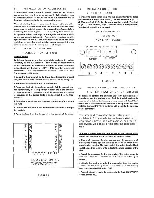
AUXILIARY BOARD<br />
To install the board simply snap the two stand-offs into the holes<br />
provided on the leg of the mounting bracket. Terminal #I (N.O.),<br />
#2 (Common), #3 (N.C.) for the open auxiliary switch. Terminal<br />
#4 (N.O.), #5 (Common), #6 (N.C.) for the close auxiliary switch.<br />
Terminals 7, 8 and 9 are not used.<br />
NELES-JAMESBURY<br />
300-0017-00<br />
AUXILIARY BOARD<br />
FIGURE 2<br />
2.5 INSTALLATION OF THE TWO EXTRA<br />
SPDT LIMIT SWITCH OPTION (EH5089):<br />
The linkage kit contains two pre-wired SPDT limit switch packages,<br />
wiring labels and the auxiliary board. Each limit switch package is<br />
made up of: a limit switch housing, a cam, a prewired 5 AMP limit<br />
switch with a female connector. Once the auxiliary board has been<br />
installed the two SPDT limit switches will plug into the auxiliary<br />
board connectors.<br />
The standard convention for installing limit<br />
switches in N-J products is: the lower switch will<br />
control or indicate the close position, and the upper<br />
switch will control or indicate the open position.<br />
To install a switch package onto the top of the existing motor<br />
control limit switches follow the steps as outlined below:<br />
I. Slide a fully assembled switch package over the cam/gear shaft<br />
and snap the locking legs into the holes on top of the OPEN motor<br />
control switch housing. The lower switch (the switch installed first)<br />
could be used for control or to indicate the close position of the<br />
valve.<br />
2. Repeat the procedure for the next switch. This switch could be<br />
used for control or to indicate when the valve is in the open<br />
position.<br />
3. Attach the lead wire with the connector into the mating<br />
connector on the auxiliary board. The connectors on the auxiliary<br />
board are labeled OPEN and CLOSE.<br />
4. Cam adjustment is made the same as in the CAM ADJUSTMENT<br />
section of this <strong>IMO</strong>.


