

Hydro-Flow? Model 3100 Retractable Insertion Vortex Flowmeter ...
Hydro-Flow? Model 3100 Retractable Insertion Vortex Flowmeter ...
Hydro-Flow? Model 3100 Retractable Insertion Vortex Flowmeter ...

Create successful ePaper yourself
Turn your PDF publications into a flip-book with our unique Google optimized e-Paper software.
Mechanical Installation (continued)<br />
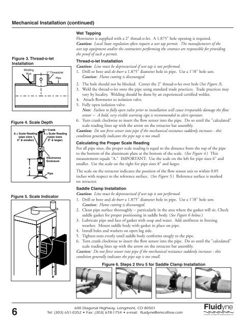
Figure 3. Thread-o-let<br />
Installation<br />
6<br />
Welding<br />
Rod<br />
Figure 4. Scale Depth<br />
A = Scale Reading<br />
(pipe sizes<br />
6" & smaller)<br />
A<br />
1<br />
2<br />
3<br />
4<br />
5<br />
6<br />
7<br />
8<br />
9<br />
10<br />
11<br />
12<br />
13<br />
0<br />
1<br />
2<br />
3<br />
4<br />
5<br />
6<br />
7<br />
8<br />
9<br />
10<br />
11<br />
12<br />
2" Threadolet<br />
Pipe<br />
Crank<br />
A = Scale Reading<br />
(pipe sizes<br />
8" & larger)<br />
Electronics<br />
Enclosure<br />
Pipe<br />
Figure 5. Scale Indicator<br />
1<br />
2<br />
3<br />
4<br />
5<br />
Sensor C L<br />
Indicator<br />
0<br />
1<br />
2<br />
3<br />
4<br />
5<br />
Wet Tapping<br />
<strong>Flow</strong>meter is supplied with a 2" thread-o-let. A 1.875" hole opening is required.<br />
Caution: Local State regulation often require a wet tap permit. The manufacturers of the<br />
wet tap equipment and/or the contractors performing the contract are responsible for providing<br />
the proof of such a permit.<br />
Thread-o-let Installation<br />
Caution: Line must be depressurized if wet tap is not performed.<br />
1. Drill or bore and de-burr a 1.875" diameter hole in pipe. Use a 1 7 /8" hole saw.<br />
Caution: Flame cutting is discouraged.<br />
2. The hole should not be blocked. Center the 2" thread-o-let over hole (See Figure 3).<br />
3. Weld the thread-o-let onto the pipe using standard trade practices. Trade practices may<br />
vary by locality. Welding should be done by an experienced certified welder.<br />
4. Attach flowmeter to isolation valve.<br />
5. Fully open isolation valve.<br />
Note: Failure to fully open valve prior to installation will cause irreparable damage the flow<br />
sensor -- A bold, very visible warning sign is recommended to alert operator.<br />
6. Turn crank clockwise to insert the flow sensor into the pipe. Do so until the "calculated"<br />
scale reading lines up with the arrow on the retractor bar assembly.<br />
Caution: Do not force sensor into pipe if the mechanical resistance suddenly increases - this<br />
condition generally indicates the pipe tap is too small.<br />
Calculating the Proper Scale Reading<br />
For all pipe sizes, the proper scale reading is equal to the distance from the top of the pipe<br />
to the bottom of the aluminum plate at the bottom of the scale. (See Figure 4.) This<br />
measurement equals "A." IMPORTANT: Use the scale on the left for pipe sizes 6" and<br />
smaller. Use the scale on the right for pipe sizes 8" and larger.<br />
The scale on the retractor indicates the position of the flow sensor axis to within 0.05<br />
inches with respect to the reference surface. (See Figure 5.) Reference surface is marked<br />
on retractor.<br />
Saddle Clamp Installation<br />
Caution: Line must be depressurized if wet tap is not performed.<br />
1. Drill or bore and de-burr a 1.875" diameter hole in pipe. Use a 1 7 /8" hole saw.<br />
Caution: Flame cutting is discouraged.<br />
2. Clean pipe surface thoroughly -- particularly in the area where the gasket will sit. Check<br />
saddle gasket for proper positioning in saddle body. (See Figure 6 below.)<br />
3. Lubricate pipe and face of gasket with soap and water. Add antifreeze in freezing<br />
weather. Mount saddle body with gasket in place on pipe.<br />
4. Install bales and washers on open lug side.<br />
5. Tighten nuts evenly until saddle body conforms snugly to the pipe.<br />
6. Turn crank clockwise to insert the flow sensor into the pipe. Do so until the "calculated"<br />
scale reading lines up with the arrow on the retractor bar assembly.<br />
Caution: Do not force sensor into pipe if the mechanical resistance suddenly increases - this<br />
condition generally indicates the pipe tap is too small.<br />
Figure 6. Steps 2 thru 5 for Saddle Clamp Installation<br />
600 Diagonal Highway, Longmont, CO 80501<br />
Tel: (303) 651-0352 • Fax: (303) 678-1754 • e-mail: fluidyne@emcoflow.com


