Atlas Copco Air Motors
Atlas Copco Air Motors
Atlas Copco Air Motors

You also want an ePaper? Increase the reach of your titles
YUMPU automatically turns print PDFs into web optimized ePapers that Google loves.
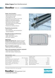
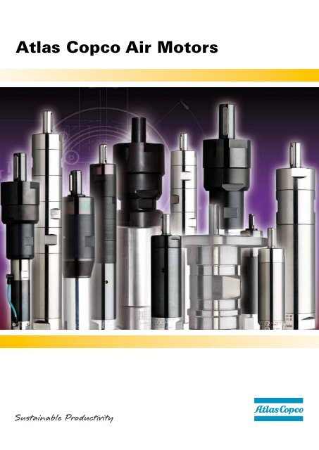
<strong>Atlas</strong> <strong>Copco</strong> <strong>Air</strong> <strong>Motors</strong>
<strong>Atlas</strong> <strong>Copco</strong> – air motors<br />
• Leading the industry in development and innovation.<br />
• Offering a comprehensive range of standard air motors.<br />
• A premier supplier of air motors engineered to meet customer<br />
requirements.<br />
• Delivering orders, on time, to customer schedules.<br />
• Offering a truly world-wide service.<br />
<strong>Atlas</strong> <strong>Copco</strong> air motors – the natural choice for<br />
design engineers in the industry of today and<br />
tomorrow.<br />
<strong>Air</strong> motor features and<br />
characteristics<br />
• <strong>Air</strong> motors are compact and lightweight. An air motor<br />
weighs only a quarter as much and occupies only one<br />
sixth of the space of an electric motor of equivalent output<br />
power. <strong>Air</strong> motors develop far more power relative to size<br />
and weight than most other motor types.<br />
• <strong>Air</strong> motors can be stalled indefinitely without overheating<br />
or sustaining any other damage. They can be started and<br />
stopped repeatedly to an unlimited extent.<br />
• Torque, speed and direction of rotation can be changed<br />
easily using simple control methodes.<br />
• Output that inherently adjusts to match the applied load.<br />
• Controllable over a wide speed range.<br />
• Virtually unaffected by hostile<br />
environment.<br />
• Smooth start-up to minimize ”shock” loading on transmission<br />
components.<br />
Our air motors are available in explosion<br />
proof certified versions, in compliance<br />
with the European Union’s ATEX<br />
Directive on equipment for potentially<br />
explosive environments.<br />
2 AT L A S C O P C O A I R M O T O R S
AT L A S C O P C O A I R M O T O R S 3
Additional information about<br />
air motors from <strong>Atlas</strong> <strong>Copco</strong><br />
Selecting the right motor has never been easier!<br />
Only enter the required working point for the application and<br />
the most suitable motor will automatically be selected. For<br />
the selection you use the web based <strong>Atlas</strong> <strong>Copco</strong> selection<br />
tool.<br />
<strong>Air</strong> motor selection program, available at<br />
www.atlascopco.com/airmotors<br />
The pocket guide is for you who want to know more about<br />
air motors. In the pocket guide you find information about<br />
function, design, motor selection and installations. Use the<br />
Ordering No. 9833 9067 01.<br />
Log in to www.atlascopco.com/airmotors<br />
24-hour access<br />
Visit our web site and browse through our on-line catalogue.<br />
You’ll find comprehensive technical information as well as<br />
details of accessories, spare parts and dimensional drawings.<br />
You can also subscribe to our news.<br />
4 AT L A S C O P C O A I R M O T O R S
Contents<br />
• Introducing the air motor .................................. 6<br />
• Methods of modifying motor output ................. 7<br />
– Throttling<br />
– Pressure regulation<br />
• Using the catalogue .......................................... 7<br />
– Motor data, specification and performance curves<br />
– Understanding the performance<br />
– Curves<br />
– Installation<br />
– Motor selection<br />
• Introduction to <strong>Atlas</strong> <strong>Copco</strong> air motors<br />
and gear units .................................................... 8<br />
• LZB vane motors introduction ......................... 10<br />
– Shaft loading<br />
– Mounting<br />
– Connection<br />
– Hose dimensions<br />
• LZB vane motors: data, specification<br />
and performance curves .................................. 14<br />
– LZB 14........................................................................... 14<br />
– LZB 14R......................................................................... 16<br />
– LZB 22.......................................................................... 18<br />
– LZB 22R ....................................................................... 20<br />
– LZB 22LR ..................................................................... 21<br />
– LZB 33.......................................................................... 22<br />
– LZB 34R ....................................................................... 24<br />
– LZB 33LR, LZB 34R LR................................................ 25<br />
– LZB 33 high torque ...................................................... 26<br />
– LZB 33/34R with brake ................................................ 28<br />
– LZB 42.......................................................................... 30<br />
– LZB 46.......................................................................... 34<br />
– LZB 54.......................................................................... 38<br />
– LZB 66........................................................................... 42<br />
– LZB 77........................................................................... 44<br />
• Accessories for LZB motors ............................ 46<br />
• LZL vane motors introduction ......................... 50<br />
– Shaft loading<br />
– Mounting<br />
– Connection<br />
– Hose dimensions<br />
• LZL vane motors: data, specification<br />
and performance curves .................................. 52<br />
– LZL Power motors<br />
– LZL Lubrication free motors<br />
– LZL Stainless steel motors<br />
• LZL vane motor/gear unit combinations .......... 56<br />
– Helical gear units type BG<br />
– Shaft loading<br />
– Calculating sprocket or gearwheel dimensions<br />
– Operating speed<br />
– Mounting<br />
– Temperature<br />
• LZL air motors: with helical gear units<br />
data, specification and performance curves ... 58<br />
– LZL 05 .......................................................................... 58<br />
– LZL 15 .......................................................................... 60<br />
– LZL 25 .......................................................................... 62<br />
– LZL 35 ........................................................................... 64<br />
• Accessories for LZL motors ........................... 68<br />
• Choosing your motor ...................................... 70<br />
– The Working Point<br />
– <strong>Atlas</strong> <strong>Copco</strong> airmotor selection guide<br />
– Starting torque and stall torque<br />
– Accelerating a load to speed<br />
– Shaft loading<br />
– Silencing<br />
– Temperature<br />
– Hostile environments<br />
– <strong>Atlas</strong> <strong>Copco</strong> air motor selection program<br />
• Installing your air motor .................................. 72<br />
– <strong>Air</strong>lines<br />
– Recommended hose connectors<br />
– <strong>Air</strong> preparation<br />
– Lubrication<br />
– Control valves for air motors<br />
– Installation examples<br />
AT L A S C O P C O A I R M O T O R S 5
Torque<br />
[100%]<br />
100<br />
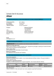
Introducing the air<br />
motor<br />
The air motor is one of the toughest and most<br />
versatile power units available to today´s<br />
design engineer. It is easy to control over a<br />
wide speed range, and it produces maximum<br />
torque where it is often most needed – at start<br />
up.<br />
The performance of an air motor is dependant on the inlet<br />
pressure. At a constant inlet pressure, ungoverned air<br />
motors exhibit the characteristic linear output torque/speed<br />
relationship. Figure 1.<br />
However, by simply regulating the air supply, using the<br />
techniques of throttling or pressure regulation, the output of<br />
an air motor can be easily modified.<br />
The free speed and torque can be regulated down to 50%<br />
for an LZB air motor. The free speed for an LZL can be regulated<br />
down to 10% and the torque can be regulated down to<br />
20%. The shaded areas in figure 2 illustrate this.<br />
50<br />
Torque<br />
[Nm]<br />
50 100<br />
Speed [100%]<br />
Torque<br />
[100%]<br />
100<br />
Speed [r/min]<br />
10 50 100<br />
Speed [100%]<br />
LZB LZL<br />
6 AT L A S C O P C O A I R M O T O R S<br />
50<br />
20<br />
Figure 1<br />
Figure 2<br />
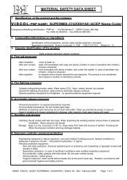
It should be noted that all vane air motors produce a variable<br />
starting torque, due to the position of the vanes in the motor<br />
when it is started. The variation differs between motor types<br />
and must be checked on an individual basis.<br />
The power that an air motor produces is a function of torque<br />
and speed. All ungoverned air motors produce the same characteristic<br />
power curve, with maximum power occurring at<br />
around 50% of the free speed. The torque produced at this<br />
point is often referred to as ”torque at maximum output.”<br />
The performance curves for an ungoverned air motor operating<br />
at a constant air pressure are illustrated in figure 3.<br />
Torque<br />
[Nm]<br />
Stall<br />
torque<br />
Min<br />
starting<br />
torque<br />
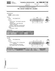
The use of gear units<br />
Torque<br />
Power<br />
Speed [r/min]<br />
Figure 3<br />
<strong>Air</strong> motors operate at high speed and, although they can be<br />
controlled over a wide speed range, the output characteristics<br />
are not always suitable for the application. To achieve the<br />
required output an appropriate gear unit can be selected. The<br />
ability to change the output by use of a gear unit is illustrated<br />
in figure 4.<br />
Torque<br />
[Nm]<br />
4:1<br />
2:1<br />
1:1, 2:1, 4:1 = gear ratios<br />
The planetary and helical gear units used by <strong>Atlas</strong> <strong>Copco</strong><br />
have a high level of efficiency that can be assumed to be<br />
100%. The power output remains virtually unchanged also<br />
when gears are used.<br />
1:1<br />
Torque<br />
Power<br />
Speed [r/min]<br />
Figure 4
Methods of modifying motor<br />
output<br />
Throttling<br />
A throttle is usually fitted into the motor´s inlet hose, although<br />
it can also be fitted into the exhaust hose. When it is<br />
desirable to maintain a high starting torque but reduce running<br />
speed – throttling is the best method of modifying the<br />
motor´s output, Figure 5.<br />
Torque<br />
[Nm]<br />
Pressure regulation<br />
When using a pressure regulator it is mostly fitted into the<br />
motor´s inlet hose. The use of pressure regulation is ideal<br />
when control of the stall torque is required and a high starting<br />
torque is not so important, Figure 6.<br />
Torque<br />
[%]<br />
100<br />
Par<br />
[Nm]<br />
Speed [r/min]<br />
Operating pressure<br />
7 bar<br />
6 bar<br />
5 bar<br />
4 bar<br />
3 bar<br />
100<br />
Speed [%]<br />
Using the catalogue<br />
Motor data, specification and performance<br />
curves<br />
Velocidad [r/min]<br />
Figure 5<br />
Figure 6<br />
For each <strong>Atlas</strong> <strong>Copco</strong> motor/gear unit combination the following<br />
information is presented in this catalogue.<br />
1. Tabular Data – Summary of main performance<br />
parameters.<br />
2.Dimensional drawings.<br />
3.Performance curves.<br />
Notes on performance data<br />
The performance data stated in this catalogue is valid for an<br />
air supply pressure of 6.3 bar (91 psi), gauge. <strong>Air</strong> consumption<br />
values are for free air delivery – (ie, the volume the consumed<br />
air would occupy if allowed to expand to atmospheric<br />
pressure).<br />
The direction of rotation for a motor is always stated looking<br />
from the back of the motor. Figure 7 illustrate clockwise rotation.<br />
Figure 7<br />
Understanding the performance curves<br />
The output of an air motor is most clearly seen from its<br />
performance curves Figure 8. For each motor/gear unit the<br />
power, torque and air consumption are shown as a function<br />
of speed.<br />
The diagrams shown apply to an inlet pressure of 6.3 bar, to<br />
calculate performance at other pressures refer to page 70 in<br />
this catalogue.<br />
Torque<br />
[Nm]<br />
Power<br />
[kW]<br />
Max<br />
output<br />
Torque<br />
at max<br />
output<br />
Motor selection<br />
Guidelines on motor selection are given on page 70 in this<br />
catalogue – Choosing Your Motor.<br />
Installation<br />
Power<br />
Torque<br />
<strong>Air</strong> cons.<br />
[l/s]<br />
<strong>Air</strong>. cons.<br />
Speed [r/min]<br />
Note. The starting torque<br />
produced by an air motor is<br />
variable and depends on vane<br />
position. These diagrams<br />
do not indicate the starting<br />
torque – this can be obtained<br />
from data tables, where the<br />
minimum value is shown.<br />
Figure 8<br />
General installation recommendations are given on page 72.<br />
Details specific to a motor are shown in the section relevant<br />
to that motor type.<br />
AT L A S C O P C O A I R M O T O R S 7
Introduction to <strong>Atlas</strong> <strong>Copco</strong><br />
air motors and gear units<br />
LZB Vane motors – 0.1 kW to 2.9 kW<br />
Type LZB <strong>Atlas</strong> <strong>Copco</strong> vane motors are compact in design,<br />
light in weight, and available with a host of different gear ratios<br />
to meet a variety of speed and torque requirements. They<br />
are particularly suited to be built into hand held machines, or<br />
indeed any industrial equipment.<br />
Planetary gear units<br />
<strong>Atlas</strong> <strong>Copco</strong> planetary gear units are particularly suited for<br />
use with LZB vane motors. The gear and motor components<br />
can be accommodated within a single, extremely compact<br />
housing where they provide high torque capacity for their<br />
size and exceptional efficiency, Figure 9.<br />
8 AT L A S C O P C O A I R M O T O R S<br />
Figure 9<br />
Stainless steel air motors<br />
<strong>Atlas</strong> <strong>Copco</strong>’s stainless steel motors enlarge the field of applications<br />
to areas where the environment is corrosive. This<br />
can be in the food processing industries where corroding<br />
detergents are used or in the chemical industry where the<br />
atmosphere as such is corrosive.<br />
<strong>Atlas</strong> <strong>Copco</strong>’s stainless steel motors have a “clean“ design.<br />
Their smooth surfaces are cylindrical with no pockets where<br />
dirt can collect. The motors are easy to clean.<br />
The motors have double seals in Viton at the shaft end to<br />
prevent water from entering the gears.<br />
The grease in the motor complies with NSF H1 and FDA<br />
21CFR § 178.3570.<br />
Explosion proof<br />
Our air motors are available in explosion proof certified<br />
versions, in compliance with the European Union.s ATEX<br />
Directive on equipment for potentially explosive environments.<br />
Ex-Certified air motors are ideal in hazardous environments,<br />
where sparks or high outer temperatures might otherwise<br />
ignite explosive gases, vapour or dust.
Lubrication free air motors<br />
<strong>Atlas</strong> <strong>Copco</strong>’s lubrication free air motors are<br />
equipped with low-friction vanes, sealed bearings<br />
and vented cylinder plates. Since they<br />
release no lubricants into the air, they offer a<br />
viable drive solution for sensitive processes<br />
and hygienic environments where oil contamination<br />
would be at best a problem and, at<br />
worst, a catastrophe.<br />
LZB 33 high torque –<br />
low speed air motors<br />
Accomplishing high torques generally calls for<br />
very large motors with correspondingly high air<br />
consumption. The LZB 33 high torque/low speed<br />
air motors are based on the combination of LZB<br />
33, the work horse in <strong>Atlas</strong> <strong>Copco</strong>´s air<br />
motor program, and the gears<br />
used in the large LZB 42-54<br />
motors. This gives a compact<br />
motor/gear package. The gears<br />
are dimensioned to stand being loaded at full stall torque<br />
indefinitely. Competing low speed air motors often have to<br />
limit their output torques to prevent gear breakage.<br />
LZB 22LR and 33LR –<br />
low speed air motors<br />
When there is a need for low speed only, the LR<br />
motors offer a complete and low price solution<br />
compared to the high torque LZB 33 airmotors.<br />
<strong>Motors</strong> with brake<br />
The most popular vane motors, LZB 33, are<br />
available with parking brake. This brake is located<br />
between the motor and the gear. It is a disc brake<br />
that is spring activated when the motor is not<br />
running. When the motor is started the brake is<br />
released by a built in pneumatic piston. The<br />
brake is used when it is important<br />
that the output shaft must not<br />
turn when the motor isn’t<br />
running and a torque is applied<br />
on the shaft.<br />
A: Clockwise rotation<br />
AR: Reversible<br />
AV: Anti-clockwise rotation<br />
L: Lubrication free<br />
LB: With brake module<br />
LR: Low speed<br />
R: Stainless steel<br />
RL: Stainless steel, lubrication free<br />
RLB: Stainless steel, with brake module<br />
RLR: Stainless steel, low speed<br />
Table 1 illustrates what features the letters in the motor<br />
designation stands for. Table 1<br />
LZL Vane motors – 1.3 kW to 6.5 kW<br />
Type LZL <strong>Atlas</strong> <strong>Copco</strong> vane motors have been designed to<br />
offer outstanding starting and low speed performance. These<br />
general purpose motors are powerful, rugged and hard wearing,<br />
Figure 10.<br />
Helical gear units<br />
<strong>Atlas</strong> <strong>Copco</strong> helical gear units are normally fitted to Type LZL<br />
vane motors. Standard units are highly efficient, providing<br />
speeds of 500 r/min down to 15 r/min at torques of up to<br />
4500 Nm. The gear unit is flange-coupled to the motor and<br />
the shafts are joined by a flexible coupling, Figure 11.<br />
5000 r/min<br />
500 r/min<br />
Figure 10<br />
Figure 11<br />
AT L A S C O P C O A I R M O T O R S 9
1 0 AT L A S C O P C O A I R M O T O R S
LZB<br />
LZB<br />
AT L A S C O P C O A I R M O T O R S 11
LZB Vane motors<br />
Introduction<br />
LZB vane motors are designed to provide high performance<br />
and high standards of reliability. Typically, they are characterized<br />
by a high power output and small physical size, Figure<br />
12.<br />
The design of the motor is chosen to be long and slim. This<br />
gives a number of advantages like a high power to volume<br />
ratio, a low air consumption and long vane life. All motors<br />
utilise five vanes, which are supplied with vane air, to ensure<br />
excellent starting and low speed performance. Multi-step<br />
planetary gears are used to meet the torque and speed<br />
requirements of the application, offering high efficiency with<br />
compact dimensions.<br />
Shaft loading<br />
The maximum allowable loads on a given motor´s output<br />
shaft are illustrated in Figure 13, 14. The relevant load curve<br />
code for a motor is stated in the data tables for each specific<br />
motor designation, under the ”Shaft load code” column.<br />
These values have been calculated for shaft and bearing working<br />
lives of 10 million turns. To achieve a working life of 100<br />
million turns, the loading factor must be halved.<br />
Fr<br />
Threaded<br />
Fa Fa<br />
shaft<br />
Fr<br />
(N)<br />
450<br />
400<br />
350<br />
300<br />
250<br />
200<br />
150<br />
100<br />
50<br />
0<br />
Curve a<br />
Curve b<br />
Curve c<br />
Figure 13<br />
500 1000<br />
1500 2000<br />
2500<br />
1 2 AT L A S C O P C O A I R M O T O R S<br />
Figure 12<br />
Fa<br />
(N)<br />
Fr<br />
(N)<br />
3500<br />
3000<br />
2500<br />
2000<br />
1500<br />
1000<br />
Fr<br />
(N)<br />
4000<br />
3000<br />
2000<br />
1000<br />
500<br />
500<br />
Curve e<br />
Curve g<br />
1000 1500 2000 2500 3000 3500 4000 4500<br />
Curve h<br />
Curve g<br />
Curve f<br />
Curve e<br />
Cylindric<br />
shaft<br />
Fr<br />
(N)<br />
2000<br />
1500<br />
1000<br />
500<br />
1000<br />
Curve d<br />
Curve c<br />
Curve b<br />
Curve a<br />
2000<br />
A = 20 mm<br />
A = 15 mm<br />
A = 20 mm<br />
A = 15 mm<br />
500<br />
Coversion factor<br />
1N = 0.225 lbf<br />
1000<br />
A = 20 mm<br />
A = 15 mm<br />
A = 9 mm<br />
A = 8 mm<br />
3000<br />
Fr<br />
1500<br />
4000<br />
A<br />
2000<br />
5000<br />
Fa<br />
(N)<br />
6000<br />
Fa<br />
5000<br />
Fa<br />
(N)<br />
Figure 14<br />
7000<br />
Fa<br />
(N)<br />
Threa<br />
shaft
Mounting<br />
Type LZB vane motors may be mounted in any position. To<br />
facilitate this, flange and foot mounting are available for each<br />
motor, Figure 15.<br />
Connection<br />
Non-Reversible Motor<br />
When the compressed air supply is connected to the inlet,<br />
the direction of rotation will be as shown in Figure 16. If the<br />
exhaust air is to be piped away, a hose should be connected<br />
to the exhaust outlet. (EXH).<br />
Certain models have a third outlet, which can be plugged<br />
without affecting the performance of the motor.<br />
Clockwise<br />
rotation<br />
Anti-clockwise<br />
rotation<br />
Figure 16<br />
Hose size up to 3m length.<br />
Motor<br />
Type<br />
Inlet<br />
connection<br />
thread<br />
(BSP) (NPTF)<br />
Foot<br />
Flange<br />
Figure 15<br />
Exhaust<br />
connection<br />
thread<br />
(mm)<br />
Reversible Motor<br />
The compressed air supply should be connected to the inlet<br />
that gives the desired direction of rotation, Figure 17.<br />
The inlet not in use functions as an additional outlet: it must<br />
not be plugged.<br />
Hose dimensions<br />
1 2<br />
1 2<br />
Figure 17<br />
Information on hose dimensions recommended for use with<br />
type LZB air motors is detailed in Table 2. These dimensions<br />
are valid for hose lengths up to 3 m. If lengths above that are<br />
used, choose a one size larger hose.<br />
Inlet<br />
hose<br />
diameter<br />
(mm)<br />
Exhaust hose<br />
diameter<br />
(Non-reversible)<br />
(mm)<br />
Exhaust hose<br />
diameter<br />
(Reversible)<br />
(mm)<br />
LZB 14 1/8" – 1/8" 5.0 8.0 6.3<br />
LZB 22 1/8" – 1/4" 6.3 10.0 8.0<br />
LZB 33 1/4" – 1/4" 8.0 10.0 8.0<br />
LZB 42 1/4" – 1/2" 10.0 13.0 13.0<br />
LZB 46 1/4" – 1/2" 10.0 16.0 13.0<br />
LZB 54 3/8" – 1/2" 13.0 16.0 13.0<br />
LZB 66 3/8" – 3/4" 13.0 20.0 13.0<br />
LZB 77<br />
Table 2<br />
1/2" 1/2" - 14 – 16.0 – 16.0<br />
AT L A S C O P C O A I R M O T O R S 1 3
Vane motors LZB 14<br />
Lubrication free versions<br />
LZB 14L<br />
0.10 – 0.16 kW<br />
0.14 – 0.22 hp<br />
For EX certification according to the ATEX directive<br />
(Ex II 2G T4 IIC D110°C) use Ordering No. 9834 1107 00<br />
(book as one delivery together with motor).<br />
EX certification valid for fixtured mounted use only.<br />
Data at air pressure 6.3 bar (91psi)<br />
Type 1)<br />
Ordering No.<br />
Max output Speed<br />
at max<br />
Torque at max<br />
output<br />
Min starting<br />
torque<br />
Free<br />
<strong>Air</strong> cons. at<br />
max output Weight<br />
Shaft<br />
output<br />
speed<br />
loading<br />
r/min<br />
r/min<br />
code 2)<br />
Keyed Threaded<br />
Keyed Threaded<br />
Shaft Shaft Type Shaft Shaft kW hp Nm Ibf.ft Nm Ibf.ft l/s cfm kg lb<br />
Clockwise rotation<br />
Standard<br />
Lubrication free<br />
LZB 14<br />
LZB 14L<br />
A190- 8411 0110 03 8411 0111 02 A190- 8411 0113 00 8411 0114 09 0.16 0.22 9100 0.17 0.12 0.26 0.19 19500 4.2 8.9 0.30 0.66 a<br />
A048- 8411 0110 11 8411 0111 10 A048- 8411 0113 18 8411 0114 17 0.16 0.22 2200 0.70 0.50 1.0 0.73 4700 4.2 8.9 0.30 0.66 a<br />
A029- 8411 0110 29 8411 0111 28 A029- 8411 0113 26 8411 0114 25 0.16 0.22 1400 1.1 0.78 1.7 1.2 2800 4.2 8.9 0.30 0.66 a<br />
A012- 8411 0110 37 8411 0111 36 A012- 8411 0113 34 8411 0114 33 0.16 0.22 530 2.9 2.1 4.2 3.1 1100 4.2 8.9 0.33 0.73 a<br />
A007- 8411 0110 45 8411 0111 44 A007- 8411 0113 42 8411 0114 41 0.16 0.22 330 4.7 3.4 7.0 5.1 690 4.2 8.9 0.33 0.73 a<br />
Anti-clockwise rotation<br />
LZB 14 LZB 14L<br />
AV190- 8411 0116 07 – AV190- 8411 0117 06 – 0.16 0.22 9100 0.17 0.12 0.26 0.19 19500 4.2 8.9 0.30 0.66 a<br />
AV048- 8411 0116 15 – AV048- 8411 0117 14 – 0.16 0.22 2200 0.70 0.50 1.0 0.73 4700 4.2 8.9 0.30 0.66 a<br />
AV029- 8411 0116 23 – AV029- 8411 0117 22 – 0.16 0.22 1400 1.1 0.78 1.7 1.2 2800 4.2 8.9 0.30 0.66 a<br />
AV012- 8411 0116 31 – AV012- 8411 0117 30 – 0.16 0.22 530 2.9 2.1 4.2 3.1 1100 4.2 8.9 0.33 0.73 a<br />
AV007- 8411 0116 49 – AV007- 8411 0117 48 – 0.16 0.22 330 4.7 3.4 7.0 5.1 690 4.2 8.9 0.33 0.73 a<br />
Reversible<br />
LZB 14 LZB 14L<br />
AR140- 8411 0112 01 – AR140- 8411 0115 08 – 0.10 0.14 6500 0.15 0.11 0.19 0.14 13000 3.6 7.6 0.30 0.66 a<br />
AR034- 8411 0112 19 – AR034- 8411 0115 16 – 0.10 0.14 1600 0.60 0.43 0.78 0.57 3100 3.6 7.6 0.30 0.66 a<br />
AR020- 8411 0112 27 – AR020- 8411 0115 24 – 0.10 0.14 950 1.0 0.72 1.3 0.95 1900 3.6 7.6 0.30 0.66 a<br />
AR008- 8411 0112 35 – AR008- 8411 0115 32 – 0.10 0.14 380 2.5 1.8 3.1 2.3 760 3.6 7.6 0.33 0.73 a<br />
AR005- 8411 0112 43 – AR005- 8411 0115 40 – 0.10 0.14 230 4.1 3.0 5.0 3.6 460 3.6 7.6 0.33 0.73 a<br />
1) Suffix. -11 = Keyed Shaft -12 = Threaded Shaft. 2) For Shaft loading curves, see page 12. NOTE: The lubrication free motors have 95% of shown free speed<br />
Dimensions (mm)<br />
Keyed shaft (-11) Threaded shaft (-12)<br />
Non-Reversible<br />
*) +9.8 mm for LZB 14 A012, A007, AR008, AR005,<br />
AV 012, AV 007<br />
1 4 AT L A S C O P C O A I R M O T O R S<br />
Optional Mountings<br />
Foot<br />
Ordering No. 4430 0189 80<br />
Reversible<br />
”<br />
”<br />
5/16" -24 UNF<br />
Flange<br />
Ordering No. 4430 0165 85<br />
Optional accessories<br />
page 46.
kW<br />
0.18<br />
0.16<br />
0.14 0.35<br />
0.12 0.30<br />
0.10 0.25<br />
0.08 0.20<br />
0.06 0.15<br />
0.04 0.10<br />
0.02 0.05<br />
kW<br />
0.18<br />
0.16<br />
0.14<br />
0.12<br />
0.10<br />
0.08<br />
0.06<br />
0.04<br />
0.02<br />
kW<br />
0.18<br />
0.16<br />
0.14<br />
0.12<br />
0.10<br />
0.08<br />
0.06<br />
0.04<br />
0.02<br />
kW<br />
0.10<br />
0.08<br />
0.06<br />
0.04<br />
0.02<br />
kW<br />
0.10<br />
0.08<br />
0.06<br />
0.04<br />
0.02<br />
kW<br />
0.10<br />
0.08<br />
0.06<br />
0.04<br />
0.02<br />
Nm LZB 14 A190 l/s<br />
5<br />
4<br />
3<br />
2<br />
1<br />
4000 8000 12000 16000 20000<br />
Nm LZB 14 A029 l/s<br />
2.4<br />
2.0<br />
1.6<br />
1.2<br />
0.8<br />
0.4<br />
5<br />
4<br />
3<br />
2<br />
1<br />
500 1000 1500 2000 2500 3000<br />
Nm LZB 14 A007 l/s<br />
9<br />
8<br />
7<br />
6<br />
5<br />
4<br />
3<br />
2<br />
1<br />
100 200 300 400 500 600 700<br />
5<br />
4<br />
3<br />
2<br />
1<br />
Nm LZB 14 AR140 l/s<br />
5<br />
0.3<br />
0.2<br />
0.1<br />
3000 6000 9000 12000 15000<br />
Nm LZB 14 AR020 l/s<br />
2.0<br />
5<br />
1.6<br />
1.2<br />
0.8<br />
0.4<br />
400 800 1200 1600 2000<br />
Nm LZB 14 AR005 l/s<br />
5<br />
8<br />
6<br />
4<br />
2<br />
LZB 14 Performance curves at air pressure 6.3 bar (91psi)<br />
100 200 300 400 500<br />
Non-Reversible<br />
4<br />
3<br />
2<br />
1<br />
4<br />
3<br />
2<br />
1<br />
4<br />
3<br />
2<br />
1<br />
r/min<br />
r/min<br />
r/min<br />
r/min<br />
kW<br />
0.18<br />
0.16<br />
0.14<br />
0.12<br />
0.10<br />
0.08<br />
0.06<br />
0.04<br />
0.02<br />
kW<br />
0.18<br />
0.16<br />
0.14<br />
0.12<br />
0.10<br />
0.08<br />
0.06<br />
0.04<br />
0.02<br />
Reversible<br />
r/min<br />
r/min<br />
kW<br />
0.10<br />
0.08<br />
0.06<br />
0.04<br />
0.02<br />
kW<br />
0.10<br />
0.08<br />
0.06<br />
0.04<br />
0.02<br />
Nm LZB 14 A048 l/s<br />
1.4<br />
1.2<br />
1.0<br />
0.8<br />
0.6<br />
0.4<br />
0.2<br />
5<br />
4<br />
3<br />
2<br />
1<br />
1000 2000 3000 4000 5000<br />
Nm LZB 14 A012 l/s<br />
6<br />
5<br />
4<br />
3<br />
2<br />
1<br />
5<br />
4<br />
3<br />
2<br />
1<br />
300 600 900 1200<br />
Nm LZB 14 AR034 l/s<br />
5<br />
1.2<br />
0.8<br />
0.4<br />
500 1000 1500 2000 2500 3000 3500<br />
Nm LZB 14 AR008 l/s<br />
5<br />
5<br />
4<br />
3<br />
2<br />
1<br />
Torque<br />
[Nm]<br />
Power<br />
[kW]<br />
Max<br />
output<br />
Torque<br />
at max<br />
output<br />
100 200 300 400 500 600 700 800<br />
Power<br />
Torque<br />
<strong>Air</strong> cons.<br />
[l/s]<br />
<strong>Air</strong>. cons.<br />
4<br />
3<br />
2<br />
1<br />
4<br />
3<br />
2<br />
1<br />
r/min<br />
r/min<br />
r/min<br />
r/min<br />
Conversion factors*)<br />
1 kW = 1.34 hp<br />
1 Nm = 0.74 Ibf - ft<br />
1 l/s = 2.1 cfm<br />
1 hp = 0.75 kW<br />
1 Ibf-ft = 1.36 Nm<br />
1 cfm = 0.47 l/s<br />
Speed [r/min]<br />
For information about performance curves, see page 7.<br />
*) For more details, see page 7.<br />
AT L A S C O P C O A I R M O T O R S 1 5
Vane motors LZB 14R<br />
Lubrication free versions<br />
LZB 14RL<br />
0.10 – 0.16 kW<br />
0.14 – 0.22 hp<br />
For EX certification according to the ATEX directive<br />
(Ex II 2G T4 IIC D110°C) use Ordering No. 9834 1107 00<br />
(book as one delivery together with motor).<br />
The material used in the back head, casing and front part is<br />
stainless steel with the designation: ISO 683/XIII Type 17, SS<br />
14 2346, DIN 17440 X12CrNiS188. The material used in the<br />
outgoing shaft and gear rim has the designation: ISO 683/XIII<br />
Type 9b, SS 14 2321, DIN 17440 X22CrNi17.<br />
Data at air pressure 6.3 bar (91psi)<br />
Torque at<br />
<strong>Air</strong> cons.<br />
Designa-<br />
Designation<br />
Max output<br />
Speed<br />
at max<br />
max<br />
output<br />
Min starting<br />
torque<br />
Free<br />
at max<br />
output Weight<br />
Shaft<br />
tion<br />
Ordering Lubrication Ordering<br />
output<br />
speed<br />
loading<br />
Lubricated No.<br />
free<br />
No.<br />
r/min<br />
r/min<br />
code 1)<br />
Ibf.<br />
Ibf.<br />
Clockwise<br />
kW hp Nm ft Nm ft l/s cfm kg lb<br />
LZB 14R LZB 14RL<br />
A190-11 8411 0121 00 A190-11 8411 0122 09 0.16 0.22 9100 0.17 0.12 0.26 0.19 19500 4.2 8.9 0.37 0.82 a<br />
A048-11 8411 0121 18 A048-11 8411 0122 17 0.16 0.22 2200 0.70 0.50 1.0 0.73 4700 4.2 8.9 0.37 0.82 a<br />
A029-11 8411 0121 26 A029-11 8411 0122 25 0.16 0.22 1400 1.1 0.78 1.7 1.2 2800 4.2 8.9 0.37 0.82 a<br />
A012-11 8411 0121 34 A012-11 8411 0122 33 0.16 0.22 530 2.9 2.1 4.2 3.1 1100 4.2 8.9 0.40 0.88 a<br />
A007-11<br />
Reversible<br />
8411 0121 42 A007-11 8411 0122 41 0.16 0.22 330 4.7 3.4 7.0 5.1 690 4.2 8.9 0.40 0.88 a<br />
LZB 14R LZB 14RL<br />
AR140-11 8411 0121 59 AR140-11 8411 0122 58 0.10 0.14 6500 0.15 0.11 0.19 0.14 13000 3.6 7.6 0.37 0.82 a<br />
AR034-11 8411 0121 67 AR034-11 8411 0122 66 0.10 0.14 1600 0.60 0.43 0.78 0.57 3100 3.6 7.6 0.37 0.82 a<br />
AR020-11 8411 0121 75 AR020-11 8411 0122 74 0.10 0.14 950 1.0 0.72 1.3 0.95 1900 3.6 7.6 0.37 0.82 a<br />
AR008-11 8411 0121 83 AR008-11 8411 0122 82 0.10 0.14 380 2.5 1.8 3.1 2.3 760 3.6 7.6 0.40 0.88 a<br />
AR005-11 8411 0121 91 AR005-11 8411 0122 90 0.10 0.14 230 4.1 3.0 5.0 3.6 460 3.6 7.6 0.40 0.88 a<br />
1) For Shaft loading curves, see page 12. NOTE: The lubrication free motors have 95% of shown free speed.<br />
Dimensions (mm) Conversion factor 1 mm = 0.04 inch<br />
6,8<br />
2h7<br />
ø6h6<br />
2<br />
2<br />
17,1<br />
12<br />
52<br />
60<br />
2<br />
134*<br />
114,2*<br />
*) +9.8 mm for LZB 14R A012, A007, AR008, AR005<br />
1 6 AT L A S C O P C O A I R M O T O R S<br />
M5<br />
ø27<br />
Optional Mountings<br />
Foot<br />
Ordering No. 4430 0923 80<br />
28,2<br />
7,9<br />
R13,5<br />
29,5<br />
Non-Reversible Reversible<br />
EXH<br />
ø30h7<br />
2<br />
7,9<br />
21,8<br />
BSP 1/8”<br />
5<br />
7,9<br />
6,8 6,8<br />
1 2<br />
EXH<br />
72<br />
3,9<br />
BSP 1/8”<br />
Optional Mountings<br />
Flange<br />
Ordering No. 4430 0922 80<br />
15,5<br />
30<br />
30<br />
ø5,5<br />
Optional accessories<br />
page 46.
kW<br />
0.18<br />
0.16<br />
0.14 0.35<br />
0.12 0.30<br />
0.10 0.25<br />
0.08 0.20<br />
0.06 0.15<br />
0.04 0.10<br />
0.02 0.05<br />
Nm LZB 14R A190 l/s<br />
5<br />
4<br />
3<br />
2<br />
1<br />
4000 8000 12000 16000 20000<br />
kW<br />
0.18<br />
0.16<br />
0.14<br />
Nm LZB 14R A012 l/s<br />
0.12 6<br />
0.10 5<br />
5<br />
0.08 4<br />
4<br />
0.06 3<br />
3<br />
0.04 2<br />
2<br />
0.02 1<br />
1<br />
300 600 900 1200<br />
kW Nm LZB 14R AR140 l/s<br />
0.10<br />
5<br />
0.08<br />
0.06<br />
0.04<br />
0.02<br />
0.3<br />
0.2<br />
0.1<br />
3000 6000 9000 12000 15000<br />
kW Nm LZB 14R AR008 l/s<br />
0.10 5<br />
5<br />
0.08<br />
0.06<br />
0.04<br />
0.02<br />
4<br />
3<br />
2<br />
1<br />
100 200 300 400 500 600 700 800<br />
LZB 14R Performance curves at air pressure 6.3 bar (91psi)<br />
4<br />
3<br />
2<br />
1<br />
4<br />
3<br />
2<br />
1<br />
r/min<br />
r/min<br />
r/min<br />
r/min<br />
kW<br />
0.18<br />
0.16<br />
0.14<br />
0.12<br />
0.10<br />
0.08<br />
0.06<br />
0.04<br />
0.02<br />
Nm LZB 14R A048 l/s<br />
1.4<br />
1.2<br />
1.0<br />
0.8<br />
0.6<br />
0.4<br />
0.2<br />
Torque<br />
[Nm]<br />
Power<br />
[kW]<br />
Max<br />
output<br />
Torque<br />
at max<br />
output<br />
5<br />
4<br />
3<br />
2<br />
1<br />
1000 2000 3000 4000 5000<br />
kW Nm LZB 14R A007 l/s<br />
0.18 9<br />
0.16 8<br />
0.14 7<br />
0.12 6<br />
0.10 5<br />
5<br />
0.08 4<br />
4<br />
0.06 3<br />
3<br />
0.04 2<br />
2<br />
0.02 1<br />
1<br />
100 200 300 400 500 600 700<br />
kW Nm LZB 14R AR034 l/s<br />
0.10<br />
5<br />
0.08<br />
0.06<br />
0.04<br />
0.02<br />
1.2<br />
0.8<br />
0.4<br />
500 1000 1500 2000 2500 3000 3500<br />
kW Nm LZB 14R AR005 l/s<br />
0.10<br />
5<br />
0.08<br />
0.06<br />
0.04<br />
0.02<br />
8<br />
6<br />
4<br />
2<br />
Non-Reversible<br />
Reversible<br />
100 200 300 400 500<br />
4<br />
3<br />
2<br />
1<br />
4<br />
3<br />
2<br />
1<br />
r/min<br />
r/min<br />
r/min<br />
r/min<br />
kW<br />
0.18<br />
0.16<br />
0.14<br />
0.12<br />
0.10<br />
0.08<br />
0.06<br />
0.04<br />
0.02<br />
Power<br />
Torque<br />
Nm LZB 14R A029 l/s<br />
2.4<br />
2.0<br />
1.6<br />
1.2<br />
0.8<br />
0.4<br />
<strong>Air</strong> cons.<br />
[l/s]<br />
<strong>Air</strong>. cons.<br />
Conversion factors*)<br />
1 kW = 1.34 hp<br />
1 Nm = 0.74 Ibf - ft<br />
1 l/s = 2.1 cfm<br />
1 hp = 0.75 kW<br />
1 Ibf-ft = 1.36 Nm<br />
1 cfm = 0.47 l/s<br />
Speed [r/min]<br />
For information about performance curves, see page 7.<br />
5<br />
4<br />
3<br />
2<br />
1<br />
500 1000 1500 2000 2500 3000<br />
kW Nm LZB 14R AR020 l/s<br />
0.10 2.0<br />
5<br />
0.08<br />
0.06<br />
0.04<br />
0.02<br />
1.6<br />
1.2<br />
0.8<br />
0.4<br />
400 800 1200 1600 2000<br />
r/min<br />
r/min<br />
*) For more details, see page 7.<br />
AT L A S C O P C O A I R M O T O R S 1 7<br />
4<br />
3<br />
2<br />
1
Vane motors LZB 22<br />
Lubrication free versions<br />
LZB 22L<br />
0.16 – 0.25 kW<br />
0.22 – 0.34 hp<br />
For EX certification according to the ATEX directive<br />
(Ex II 2G T5 IIC D85°C) use Ordering No. 9834 1108 00<br />
(book as one delivery together with motor).<br />
EX certification valid for fixtured mounted use only.<br />
Data at air pressure 6.3 bar (91psi)<br />
Type 1)<br />
Ordering No.<br />
Torque at<br />
<strong>Air</strong> cons.<br />
Max output<br />
Speed<br />
at max<br />
max<br />
output<br />
Min starting<br />
torque<br />
Free<br />
at max<br />
output Weight<br />
Shaft<br />
output<br />
speed<br />
loading<br />
r/min<br />
r/min<br />
code 2)<br />
Keyed Threaded<br />
Keyed Threaded<br />
Ibf.<br />
Shaft Shaft Type Shaft Shaft kW hp Nm ft Nm Ibf.ft l/s cfm kg lb<br />
Clockwise rotation<br />
Standard<br />
Lubrication free<br />
LZB 22<br />
LZB 22L<br />
A220- 8411 0201 37 8411 0202 36 A220- 8411 0214 08 8411 0214 73 0.25 0.34 9600 0.25 0.18 0.45 0.33 21500 5.3 11.2 0.55 1.21 b<br />
A049- 8411 0201 29 8411 0202 28 A049- 8411 0214 16 8411 0214 81 0.25 0.34 2200 1.1 0.81 2.0 1.5 5000 5.3 11.2 0.55 1.21 b<br />
A036- 8411 0201 52 8411 0202 51 A036- 8411 0214 24 8411 0214 99 0.25 0.34 1650 1.5 1.1 2.7 2.0 3750 5.3 11.2 0.55 1.21 b<br />
A022- 8411 0201 11 8411 0202 10 A022- 8411 0214 32 8411 0215 07 0.25 0.34 1040 2.4 1.7 4.5 3.3 2250 5.3 11.2 0.55 1.21 b<br />
A011- 8411 0201 03 8411 0202 02 A011- 8411 0214 40 8411 0215 15 0.24 0.32 535 4.3 3.2 8.0 5.9 1140 5.3 11.2 0.75 1.65 b<br />
A008- 8411 0201 60 8411 0202 69 A008- 8411 0214 57 8411 0215 23 0.24 0.32 380 6.0 4.4 10.5 7.7 850 5.3 11.2 0.75 1.65 b<br />
A005- 8411 0201 45 8411 0202 44 A005- 8411 0214 65 8411 0215 31 0.24 0.32 235 9.9 7.3 17.0 12.5 510 5.3 11.2 0.75 1.65 b<br />
Reversible<br />
LZB 22 LZB 22L<br />
AR126- 8411 0203 35 – AR126- 8411 0215 49 – 0.16 0.22 6500 0.24 0.18 0.35 0.26 13800 5.0 10.6 0.55 1.21 b<br />
AR028- 8411 0203 27 – AR028- 8411 0215 56 – 0.16 0.22 1390 1.1 0.81 1.3 0.96 3000 5.0 10.6 0.55 1.21 b<br />
AR021- 8411 0203 68 – AR021- 8411 0215 64 – 0.16 0.22 1050 1.5 1.1 1.8 1.3 2200 5.0 10.6 0.55 1.21 b<br />
AR013- 8411 0203 19 – AR013- 8411 0215 72 – 0.16 0.22 650 2.4 1.7 3.0 2.2 1350 5.0 10.6 0.55 1.21 b<br />
AR006- 8411 0203 01 – AR006- 8411 0215 80 – 0.16 0.22 310 5.0 3.7 5.9 4.4 680 5.0 10.6 0.75 1.65 b<br />
AR005- 8411 0203 50 – AR005- 8411 0215 98 – 0.16 0.22 240 6.7 4.9 8.0 5.9 500 5.0 10.6 0.75 1.65 b<br />
AR003- 8411 0203 43 – AR003- 8411 0216 06 – 0.16 0.22 140 10.8 8.0 13.4 9.9 300 5.0 10.6 0.75 1.65 b<br />
1) Suffix. -11 = Keyed Shaft -12 = Threaded Shaft. 2) For Shaft loading curves, see page 12.<br />
NOTE: The lubrication free motors have 95% of shown free speed.<br />
Dimensions (mm)<br />
for<br />
Keyed shaft (-11)<br />
Optional Mountings<br />
Foot<br />
Ordering No.<br />
1 8 AT L A S C O P C O A I R M O T O R S<br />
Reversible<br />
Non-Reversible<br />
Threaded shaft (-12)<br />
Optional Mountings<br />
Flange<br />
Ordering No.<br />
with holes<br />
without holes<br />
Optional accessories<br />
page 46.
kW Nm LZB 22 A220 l/s<br />
0.30 0.6<br />
0.25 0.5<br />
0.20 0.4<br />
0.15 0.3<br />
6<br />
0.10 0.2<br />
4<br />
0.05 0.1<br />
2<br />
10000 20000 r/min<br />
kW Nm LZB 22 A022 l/s<br />
0.25<br />
0.20<br />
0.15<br />
0.10<br />
0.05<br />
5<br />
4<br />
3<br />
2<br />
1<br />
500 1000 1500 2000 2500 r/min<br />
kW Nm LZB 22 A005 l/s<br />
0.25<br />
0.20<br />
0.15<br />
0.10<br />
0.05<br />
20<br />
16<br />
12<br />
8<br />
4<br />
LZB 22, LZB 22R Performance curves at air pressure 6.3 bar (91psi)<br />
100 200 300 400 500 600<br />
6<br />
4<br />
2<br />
6<br />
4<br />
2<br />
kW<br />
0.18<br />
Nm LZB 22 AR126 l/s<br />
0.15 0.5<br />
0.12 0.4<br />
0.09 0.3<br />
6<br />
0.06 0.2<br />
4<br />
0.03 0.1<br />
2<br />
r/min<br />
4000 8000 12000 r/min<br />
kW<br />
0.18<br />
0.15<br />
Nm LZB 22 AR013 l/s<br />
0.12 4<br />
0.09 3<br />
6<br />
0.06 2<br />
4<br />
0.03 1<br />
2<br />
300 600 900 1200 1500 r/min<br />
kW<br />
0.18<br />
Nm LZB 22 AR003 l/s<br />
0.15 20<br />
0.12 16<br />
0.09 12<br />
6<br />
0.06 8<br />
4<br />
0.03 4<br />
2<br />
100 200 300<br />
r/min<br />
kW<br />
0.25<br />
0.20<br />
0.15<br />
0.10<br />
0.05<br />
Non-Reversible<br />
Nm LZB 22 A049 l/s<br />
2.5<br />
2.0<br />
1.5<br />
1.0<br />
0.5<br />
2000 4000 6000 r/min<br />
kW Nm LZB 22 A011 l/s<br />
0.25<br />
0.20<br />
0.15<br />
0.10<br />
0.05<br />
10<br />
8<br />
6<br />
4<br />
2<br />
Torque<br />
[Nm]<br />
Power<br />
[kW]<br />
Max<br />
output<br />
Torque<br />
at max<br />
output<br />
6<br />
4<br />
2<br />
6<br />
4<br />
2<br />
200 400 600 800 1000 1200 r/min<br />
Reversible<br />
kW<br />
0.18<br />
Nm LZB 22 AR028 l/s<br />
0.15 2.0<br />
0.12 1.6<br />
0.09 1.2<br />
6<br />
0.06 0.8<br />
4<br />
0.03 0.4<br />
2<br />
1000 2000 3000 r/min<br />
kW<br />
0.18<br />
Nm LZB 22 AR006 l/s<br />
0.15 10<br />
0.12 8<br />
0.09 6<br />
6<br />
0.06 4<br />
4<br />
0.03 2<br />
2<br />
200 400 600 800<br />
r/min<br />
kW Nm LZB 22 A036 l/s<br />
0.30 3.0<br />
0.25 2.5<br />
0.20 2.0<br />
0.15 1.5<br />
6<br />
0.10 1.0<br />
4<br />
0.05 0.5<br />
2<br />
1000 2000 3000 4000 r/min<br />
kW Nm<br />
12<br />
LZB 22 A008 l/s<br />
0.25 10<br />
0.20 8<br />
0.15 6<br />
6<br />
0.10 4<br />
4<br />
0.05 2<br />
2<br />
Power<br />
Torque<br />
<strong>Air</strong> cons.<br />
[l/s]<br />
<strong>Air</strong>. cons.<br />
Conversion factors*)<br />
1 kW = 1.34 hp<br />
1 Nm = 0.74 Ibf - ft<br />
1 l/s = 2.1 cfm<br />
1 hp = 0.75 kW<br />
1 Ibf-ft = 1.36 Nm<br />
1 cfm = 0.47 l/s<br />
Speed [r/min]<br />
For information about performance curves, see page 7.<br />
200 400 600 800 1000 r/min<br />
kW Nm LZB 22 AR021 l/s<br />
0.18 2.4<br />
0.15 2.0<br />
0.12 1.6<br />
0.09 1.2<br />
6<br />
0.06 0.8<br />
4<br />
0.03 0.4<br />
2<br />
500 1000 1500 2000 2500 r/min<br />
kW Nm LZB 22 AR005 l/s<br />
0.18 12<br />
0.15 10<br />
0.12 8<br />
0.09 6<br />
6<br />
0.06 4<br />
4<br />
0.03 2<br />
2<br />
200 400 600 r/min<br />
*) For more details, see page 7.<br />
AT L A S C O P C O A I R M O T O R S 1 9
Stainless steel<br />
vane motors LZB 22R<br />
Lubrication free versions LZB 22RL<br />
0.16 – 0.25 kW<br />
0.22 – 0.34 hp<br />
For EX certification according to the ATEX directive<br />
(Ex II 2G T5 IIC D85°C) use Ordering No. 9834 1108 00<br />
(book as one delivery together with motor).<br />
The material used in the back head, casing and front part is<br />
stainless steel with the designation: ISO 683/XIII Type 17, SS<br />
14 2346, DIN 17440 X12CrNiS188. The material used in the<br />
outgoing shaft and gear rim has the designation: ISO 683/XIII<br />
Type 9b, SS 14 2321, DIN 17440 X22CrNi17.<br />
Data at air pressure 6.3 bar (91psi)<br />
Designa-<br />
Designation<br />
Max output<br />
Speed<br />
at max<br />
Torque at<br />
max<br />
output<br />
Min starting<br />
torque<br />
Free<br />
<strong>Air</strong> cons. at<br />
max output Weight<br />
Shaft<br />
tion<br />
Ordering Lubrication Ordering<br />
output<br />
speed<br />
loading<br />
Lubricated No.<br />
free<br />
No.<br />
r/min<br />
r/min<br />
code<br />
Dimensions (mm)<br />
1)<br />
Ibf.<br />
Ibf.<br />
kW hp Nm ft Nm ft l/s cfm kg lb<br />
Clockwise rotation<br />
LZB 22R LZB 22RL<br />
A220-11 8411 0217 05 A220-11 8411 0219 11 0.25 0.34 9600 0.25 0.18 0.45 0.33 21500 5.3 11.2 0.63 1.21 b<br />
A049-11 8411 0217 13 A049-11 8411 0219 29 0.25 0.34 2200 1.1 0.81 2.0 1.5 5000 5.3 11.2 0.63 1.21 b<br />
A036-11 8411 0217 21 A036-11 8411 0219 37 0.25 0.34 1650 1.5 1.1 2.7 2.0 3750 5.3 11.2 0.63 1.21 b<br />
A022-11 8411 0217 39 A022-11 8411 0219 45 0.25 0.34 1040 2.4 1.7 4.5 3.3 2250 5.3 11.2 0.63 1.21 b<br />
A011-11 8411 0217 47 A011-11 8411 0219 52 0.24 0.32 535 4.3 3.2 8.0 5.9 1140 5.3 11.2 0.83 1.65 b<br />
A008-11 8411 0217 54 A008-11 8411 0219 60 0.24 0.32 380 6.0 4.4 10.5 7.7 850 5.3 11.2 0.83 1.65 b<br />
A005-11<br />
Reversible<br />
8411 0217 62 A005-11 8411 0219 78 0.24 0.32 235 9.9 7.3 17.0 12.5 510 5.3 11.2 0.83 1.65 b<br />
LZB 22R LZB 22RL<br />
AR126-11 8411 0218 79 AR126-11 8411 0220 83 0.16 0.22 6500 0.24 0.18 0.35 0.26 13800 5.0 10.6 0.63 1.21 b<br />
AR028-11 8411 0218 61 AR028-11 8411 0220 75 0.16 0.22 1390 1.1 0.81 1.3 0.96 3000 5.0 10.6 0.63 1.21 b<br />
AR021-11 8411 0219 03 AR021-11 8411 0222 16 0.16 0.22 1050 1.5 1.1 1.8 1.3 2200 5.0 10.6 0.63 1.21 b<br />
AR013-11 8411 0218 53 AR013-11 8411 0220 67 0.16 0.22 650 2.4 1.7 3.0 2.2 1350 5.0 10.6 0.63 1.21 b<br />
AR006-11 8411 0218 46 AR006-11 8411 0220 59 0.16 0.22 310 5.0 3.7 5.9 4.4 680 5.0 10.6 0.83 1.65 b<br />
AR005-11 8411 0218 95 AR005-11 8411 0222 08 0.16 0.22 240 6.7 4.9 8.0 5.9 500 5.0 10.6 0.83 1.65 b<br />
AR003-11 8411 0218 87 AR003-11 8411 0220 91 0.16 0.22 140 10.8 8.0 13.4 9.9 300 5.0 10.6 0.83 1.65 b<br />
1) For Shaft loading curves, see page 12.<br />
Performance curves are given on page 19. NOTE: The lubrication free motors have 95% of shown free speed.<br />
Keyed shaft (-11)<br />
Optional Mounting<br />
Foot<br />
Ordering No. 4430 0862 80<br />
2 0 AT L A S C O P C O A I R M O T O R S<br />
* +31.2 mm for LZB 22R A011 LZB 22R AR006<br />
LZB 22R A008 LZB 22R AR005<br />
LZB 22R A005 LZB 22R AR003<br />
Non-Reversible Reversible<br />
Optional Mounting<br />
Flange<br />
Ordering No. 4430 0861 80<br />
Optional accessories<br />
page 46.
Vane motors LZB 22 LR,<br />
LZB 22R LR<br />
Low speed reversible<br />
Maximum permitted torque 9 Nm (6.6 lbf.ft).<br />
For EX certification according to the ATEX directive (Ex II 2G T5 IIC D85°C) use<br />
Ordering No. 9834 1108 00 (book as one delivery together with motor).<br />
EX certification for LZB 22 LR valid for fixtured mounted use only.<br />
Within their working range these motors have a very steep torque curve.<br />
Speed and air consumption is relatively constant regardless of the load.<br />
Data at air pressure 6.3 bar (91psi)<br />
Dimensions LZB 22 LR (mm)<br />
Optional Mountings<br />
Foot for LZB 22 LR<br />
Ordering No. 4430 0160 80<br />
Reversible<br />
Flange for LZB 22 LR<br />
Ordering No. 4110 0984 85<br />
Dimensions LZB 22R LR (mm) Conversion factor 1mm = 0.04 inch<br />
Keyed shaft (-11)<br />
Optional Mounting<br />
Foot<br />
Ordering No. 4430 0862 80<br />
Optional accessories<br />
page 46.<br />
Designation<br />
Lubrication<br />
free<br />
*) +62 mm for LZB 22 LR5.<br />
* +62.4 mm for LZB 22R LR5<br />
<strong>Air</strong><br />
consumption Weight<br />
l/s cfm kg lb<br />
Designation<br />
Ordering<br />
Ordering<br />
Free speed<br />
Lubricated<br />
No.<br />
No.<br />
r/min<br />
LZB 22 LR100-11 8411 0212 18 LZB 22L LR100-11 8411 0216 22 100 5.8 12.3 0.95 2.11 b<br />
LZB 22 LR5-11<br />
Stainless steel<br />
8411 0212 00 LZB 22L LR5-11 8411 0216 14 5 5.8 12.3 1.35 3.00 b<br />
LZB 22R LR100-11 8411 0222 24 LZB 22RL LR100-11 8411 0222 40 100 5.8 12.3 1.03 2.11 b<br />
LZB 22R LR5-11 8411 0222 32 LZB 22RL LR5-11 8411 0222 57 5 5.8 12.3 1.43 3.00 b<br />
1) For Shaft loading curves, see page 12.<br />
Reversible<br />
Optional Mounting<br />
Flange<br />
Ordering No. 4430 0861 80<br />
Shaft<br />
loading<br />
code 1)<br />
AT L A S C O P C O A I R M O T O R S 2 1
Vane motors LZB 33<br />
Lubrication free versions LZB 33L<br />
0.23 – 0.39 kW<br />
0.31 – 0.52 hp<br />
For EX certification according to the ATEX directive<br />
(Ex II 2G T5 IIC D85°C) use Ordering No. 9834 1108 00<br />
(book as one delivery together with motor).<br />
EX certification valid for fixtured mounted use only.<br />
Data at air pressure 6.3 bar (91psi)<br />
Type 1)<br />
Ordering No.<br />
Torque at<br />
Min<br />
<strong>Air</strong> cons.<br />
Max output<br />
Speed<br />
at max<br />
max<br />
output<br />
starting<br />
torque<br />
Free<br />
at max<br />
output Weight<br />
Shaft<br />
output<br />
speed<br />
loading<br />
r/min<br />
r/min<br />
code 2)<br />
Keyed Threaded<br />
Keyed Threaded<br />
Ibf.<br />
Shaft Shaft Type Shaft Shaft kW hp Nm Ibf.ft Nm ft l/s cfm kg lb<br />
Clockwise rotation<br />
Standard<br />
Lubrication free<br />
LZB 33<br />
LZB 33L<br />
A210- 8411 0301 51 8411 0302 50 A210- 8411 0306 07 8411 0306 80 0.39 0.52 9400 0.40 0.30 0.76 0.56 20000 8.3 17.6 0.75 1.65 c<br />
A060- 8411 0301 44 8411 0302 43 A060- 8411 0306 15 8411 0306 98 0.39 0.52 2600 1.4 1.0 2.7 2.0 5600 8.3 17.6 0.75 1.65 c<br />
A033- 8411 0301 36 8411 0302 35 A033- 8411 0306 23 8411 0307 06 0.39 0.52 1460 2.6 1.9 4.9 3.6 3100 8.3 17.6 0.75 1.65 c<br />
A026- 8411 0301 28 8411 0302 27 A026- 8411 0306 31 8411 0307 14 0.39 0.52 1180 3.2 2.3 6.1 4.5 2500 8.3 17.6 0.75 1.65 c<br />
A013- 8411 0301 10 8411 0302 19 A013- 8411 0306 49 8411 0307 22 0.38 0.51 580 6.3 4.6 12.0 8.9 1230 8.3 17.6 1.02 2.25 c<br />
A007- 8411 0301 02 8411 0302 01 A007- 8411 0306 56 8411 0307 30 0.38 0.51 320 11.3 8.4 21.6 15.9 680 8.3 17.6 1.02 2.25 c<br />
A005- 8411 0301 69 8411 0302 68 A005- 8411 0306 64 8411 0307 48 0.38 0.51 259 14.0 10.3 26.8 19.8 550 8.3 17.6 1.02 2.25 c<br />
A0030- 8411 0301 77 – A0030- 8411 0306 72 – 0.36 0.48 160 21.5 15.9 40.7 30.0 340 8.3 17.6 1.50 3.31 d<br />
Reversible<br />
LZB 33 LZB 33L<br />
AR150- 8411 0303 59 – AR150- 8411 0307 63 – 0.24 0.32 7000 0.34 0.25 0.46 0.34 14000 7.8 16.5 0.75 1.65 c<br />
AR043- 8411 0303 42 – AR043- 8411 0307 71 – 0.24 0.32 1960 1.2 0.89 1.6 1.2 3840 7.8 16.5 0.75 1.65 c<br />
AR024- 8411 0303 34 – AR024- 8411 0307 89 – 0.24 0.32 1090 2.1 1.6 3.0 2.2 2090 7.8 16.5 0.75 1.65 c<br />
AR019- 8411 0303 26 – AR019- 8411 0307 97 – 0.24 0.32 880 2.7 2.0 3.7 2.7 1760 7.8 16.5 0.75 1.65 c<br />
AR009- 8411 0303 18 – AR009- 8411 0308 05 – 0.23 0.31 435 4.9 3.6 7.0 5.2 840 7.8 16.5 1.02 2.25 c<br />
AR005- 8411 0303 00 – AR005- 8411 0308 13 – 0.23 0.31 240 9.1 6.7 12.6 9.3 480 7.8 16.5 1.02 2.25 c<br />
AR004- 8411 0303 67 – AR004- 8411 0308 21 – 0.23 0.31 190 11.4 8.4 15.6 11.5 385 7.8 16.5 1.02 2.25 c<br />
AR0026- 8411 0303 75 – AR0026- 8411 0308 70 – 0.23 0.31 120 18.3 13.5 20.0 14.8 240 7.8 16.5 1.50 3.31 d<br />
1) Suffix. -11 = Keyed Shaft -12 = Threaded Sha 8411 ft. 2) For Shaft loading curves, see page 12.<br />
NOTE: The lubrication free motors have 95% o 8411 f shown free speed.<br />
Dimensions (mm)<br />
Keyed shaft (-11)<br />
Optional Mounting<br />
Foot<br />
Ordering No. 4430 0162 80<br />
for<br />
2 2 AT L A S C O P C O A I R M O T O R S<br />
LZB 33 A0030-11<br />
LZB 33 AR0026-11<br />
Reversible<br />
Non-Reversible<br />
Optional Mounting<br />
Flange<br />
Ordering No. 4110 0878 85<br />
with holes<br />
4110 0878 80 without holes<br />
Threaded shaft (-12)<br />
Optional accessories<br />
page 46.
kW<br />
0,4<br />
0,3<br />
0,2<br />
0,1<br />
kW Nm<br />
0,4<br />
0,3<br />
0,2<br />
0,1<br />
kW<br />
0,4<br />
0,3<br />
0,2<br />
0,1<br />
kW<br />
0,3<br />
0,2<br />
0,1<br />
kW<br />
0,3<br />
0,2<br />
0,1<br />
kW<br />
0,3<br />
0,2<br />
0,1<br />
Nm<br />
0,8<br />
0,6<br />
0,4<br />
0,2<br />
6<br />
5<br />
4<br />
3<br />
2<br />
1<br />
Nm<br />
24<br />
20<br />
16<br />
12<br />
8<br />
4<br />
Nm<br />
0,6<br />
0,5<br />
0,4<br />
0,3<br />
0,2<br />
0,1<br />
Nm<br />
5<br />
4<br />
3<br />
2<br />
1<br />
Nm<br />
20<br />
16<br />
12<br />
8<br />
4<br />
5000 10000 15000 20000 r/min<br />
LZB 33 A026 l/s<br />
10<br />
8<br />
6<br />
4<br />
2<br />
1000 2000 3000 r/min<br />
LZB 33 A005 l/s<br />
10<br />
8<br />
6<br />
4<br />
2<br />
200 400 600 r/min<br />
LZB 33 AR150<br />
l/s<br />
10<br />
8<br />
6<br />
4<br />
2<br />
3000 6000 9000 12000 15000 r/min<br />
LZB 33 AR019<br />
l/s<br />
10<br />
8<br />
6<br />
4<br />
2<br />
500 1000 1500 2000 r/min<br />
LZB 33 AR004<br />
LZB 33, LZB 34R Performance curves at air pressure 6.3 bar (91psi)<br />
LZB 33 A210 l/s<br />
10<br />
8<br />
6<br />
4<br />
2<br />
l/s<br />
10<br />
8<br />
6<br />
4<br />
2<br />
100 200 300 400 r/min<br />
kW<br />
0,4<br />
0,3<br />
0,2<br />
0,1<br />
kW<br />
0,4<br />
0,3<br />
0,2<br />
0,1<br />
kW<br />
0,4<br />
0,3<br />
0,2<br />
0,1<br />
kW<br />
0,3<br />
0,2<br />
0,1<br />
kW<br />
0,3<br />
0,2<br />
0,1<br />
kW<br />
0,3<br />
0,2<br />
0,1<br />
Nm<br />
3,2<br />
2,8<br />
2,4<br />
2,0<br />
1,6<br />
1,2<br />
0,8<br />
0,4<br />
Nm<br />
12<br />
10<br />
8<br />
6<br />
4<br />
2<br />
Nm<br />
48<br />
36<br />
24<br />
12<br />
Nm<br />
2,5<br />
2,0<br />
1,5<br />
1,0<br />
0,5<br />
Nm<br />
10<br />
8<br />
6<br />
4<br />
2<br />
Nm<br />
36<br />
24<br />
12<br />
Non-Reversible<br />
2000 4000 6000 r/min<br />
LZB 33 A013 l/s<br />
10<br />
8<br />
6<br />
4<br />
2<br />
300 600 900 1200 1500 r/min<br />
LZB 33 A0030 l/s<br />
12<br />
10<br />
8<br />
6<br />
4<br />
2<br />
100 200 300 400 r/min<br />
LZB 33 AR043<br />
l/s<br />
10<br />
8<br />
6<br />
4<br />
2<br />
1000 2000 3000 4000 r/min<br />
LZB 33 AR009<br />
l/s<br />
10<br />
8<br />
6<br />
4<br />
2<br />
200 400 600 800 1000 r/min<br />
50<br />
LZB 33 A060 l/s<br />
Reversible<br />
LZB 33 AR0026<br />
12<br />
10<br />
8<br />
6<br />
4<br />
2<br />
l/s<br />
10<br />
8<br />
6<br />
4<br />
2<br />
100 150 200 250 r/min<br />
kW<br />
0,4<br />
0,3<br />
0,2<br />
0,1<br />
kW<br />
0,4<br />
0,3<br />
0,2<br />
0,1<br />
kW<br />
0,3<br />
0,2<br />
0,1<br />
kW<br />
0,3<br />
0,2<br />
0,1<br />
Torque<br />
[Nm]<br />
Power<br />
[kW]<br />
Max<br />
output<br />
Torque<br />
at max<br />
output<br />
Nm<br />
5<br />
4<br />
3<br />
2<br />
1<br />
Nm<br />
20<br />
16<br />
12<br />
8<br />
4<br />
Nm<br />
4<br />
3<br />
2<br />
1<br />
Nm<br />
16<br />
12<br />
8<br />
4<br />
LZB 33 A033 l/s<br />
1000 2000 3000 r/min<br />
LZB 33 A007 l/s<br />
10<br />
8<br />
6<br />
4<br />
2<br />
200 400 600 800 r/min<br />
LZB 33 AR024<br />
l/s<br />
10<br />
8<br />
6<br />
4<br />
2<br />
500 1000 1500 2000 2500 r/min<br />
LZB 33 AR005<br />
10<br />
8<br />
6<br />
4<br />
2<br />
l/s<br />
10<br />
8<br />
6<br />
4<br />
2<br />
100 200 300 400 500 r/min<br />
Power<br />
Torque<br />
<strong>Air</strong> cons.<br />
[l/s]<br />
<strong>Air</strong>. cons.<br />
Speed [r/min]<br />
Conversion factors*)<br />
1 kW = 1.34 hp<br />
1 Nm = 0.74 Ibf - ft<br />
1 l/s = 2.1 cfm<br />
1 hp = 0.75 kW<br />
1 Ibf-ft = 1.36 Nm<br />
1 cfm = 0.47 l/s<br />
*) For more details,<br />
see page 7.<br />
AT L A S C O P C O A I R M O T O R S 2 3
Stainless steel<br />
vane motors LZB 34R<br />
Lubrication free versions LZB 34RL<br />
0.23 – 0.39 kW<br />
0.31 – 0.52 hp<br />
For EX certification according to the ATEX directive (Ex II 2G T5 IIC D85°C) use<br />
Ordering No. 9834 1108 00 (book as one delivery together with motor).<br />
The material used in the back head, casing and front part is stainless<br />
steel with the designation: ISO 683/XIII Type 17, SS 142346, DIN 17440<br />
X12CrNiS188. The material used in the outgoing shaft and gear rim has the<br />
designation: ISO 683/XIII Type 9b, SS 142321, DIN 17440 X22CrNi17.<br />
Data at air pressure 6.3 bar (91psi)<br />
Dimensions (mm) Conversion factor 1mm = 0.04 inch<br />
Keyed shaft (-11)<br />
Torque at<br />
max<br />
output<br />
Designa-<br />
Designation<br />
Max output<br />
Speed<br />
at max<br />
Min starting<br />
torque<br />
Free<br />
<strong>Air</strong> cons. at<br />
max output Weight<br />
tion<br />
Ordering Lubrication Ordering<br />
output<br />
Ibf.<br />
Ibf. speed<br />
Lubricated No.<br />
free<br />
No. kW hp r/min Nm ft Nm ft r/min l/s cfm kg lb<br />
Clockwise rotation<br />
LZB 34R LZB 34RL<br />
A210-11 8411 0337 00 A210-11 8411 0338 41 0.39 0.52 9400 0.40 0.30 0.76 0.56 20000 8.3 17.6 0.95 1.65 c<br />
A060-11 8411 0337 18 A060-11 8411 0338 58 0.39 0.52 2600 1.4 1.0 2.7 2.0 5600 8.3 17.6 0.95 1.65 c<br />
A033-11 8411 0337 26 A033-11 8411 0338 66 0.39 0.52 1460 2.6 1.9 4.9 3.6 3100 8.3 17.6 0.95 1.65 c<br />
A026-11 8411 0337 34 A026-11 8411 0338 74 0.39 0.52 1180 3.2 2.3 6.1 4.5 2500 8.3 17.6 0.95 1.65 c<br />
A013-11 8411 0337 42 A013-11 8411 0338 82 0.38 0.51 580 6.3 4.6 12.0 8.9 1230 8.3 17.6 1.2 2.25 c<br />
A007-11 8411 0337 59 A007-11 8411 0338 90 0.38 0.51 320 11.3 8.4 21.6 15.9 680 8.3 17.6 1.2 2.25 c<br />
A005-11<br />
Reversible<br />
8411 0337 67 A005-11 8411 0339 08 0.38 0.51 259 14.0 10.3 26.8 19.8 550 8.3 17.6 1.2 2.25 c<br />
LZB 34R LZB 34RL<br />
AR150-11 8411 0337 75 AR150-11 8411 0339 16 0.24 0.32 7000 0.34 0.25 0.46 0.34 14000 7.8 16.5 0.95 1.65 c<br />
AR043-11 8411 0337 83 AR043-11 8411 0339 24 0.24 0.32 1960 1.2 0.89 1.6 1.2 3840 7.8 16.5 0.95 1.65 c<br />
AR024-11 8411 0337 91 AR024-11 8411 0339 32 0.24 0.32 1090 2.1 1.6 3.0 2.2 2090 7.8 16.5 0.95 1.65 c<br />
AR019-11 8411 0338 09 AR019-11 8411 0339 40 0.24 0.32 880 2.7 2.0 3.7 2.7 1500 7.8 16.5 0.95 1.65 c<br />
AR009-11 8411 0338 17 AR009-11 8411 0339 57 0.23 0.31 435 4.9 3.6 7.0 5.2 840 7.8 16.5 1.2 2.25 c<br />
AR005-11 8411 0338 27 AR005-11 8411 0339 65 0.23 0.31 240 9.1 6.7 12.6 9.3 480 7.8 16.5 1.2 2.25 c<br />
AR004-11 8411 0338 33 AR004-11 8411 0339 73 0.23 0.31 190 11.4 8.4 15.6 11.5 385 7.8 16.5 1.2 2.25 c<br />
1) For Shaft loading curves, see page 12.<br />
Performance curves are given on page 23. NOTE: The lubrication free motors have 95% of shown free speed.<br />
* +34.5 mm for LZB 34R A011 LZB 34R AR009<br />
LZB 34R A008 LZB 34R AR005<br />
LZB 34R A005 LZB 34R AR004<br />
Optional Mounting<br />
Foot<br />
Ordering No. 4430 0855 80<br />
2 4 AT L A S C O P C O A I R M O T O R S<br />
Non-Reversible<br />
Reversible<br />
Optional Mounting<br />
Flange<br />
Ordering No. 4430 0850 80<br />
Shaft<br />
loading<br />
code 1)<br />
Optional accessories<br />
page 46.
Vane motors LZB 33 LR,<br />
LZB 34R LR<br />
Low speed reversible<br />
Maximum permitted torque 14 Nm (10.3 lbf.ft)<br />
For EX certification according to the ATEX directive (Ex II 2G T5 IIC D85°C) use Ordering<br />
No. 9834 1108 00 (book as one delivery together with motor). EX certification for LZB 33<br />
LR valid for fixtured mounted use only. For applications where low speed and high torque<br />
are required the LZB 33 high torque/low speed motors should be considered, see page<br />
26. Within their working range these motors have a very steep torque curve. Speed and<br />
air consumption is relatively constant regardless of the load.<br />
Data at air pressure 6.3 bar (91psi)<br />
Dimensions LZB 33 LR (mm)<br />
Dimensions LZB 34R LR (mm) Conversion factor 1mm = 0.04 inch<br />
Keyed shaft (-11)<br />
Optional accessories<br />
page 46.<br />
Designation<br />
Lubrication<br />
free<br />
* +33.5 mm for LZB 33 LR44, LR20<br />
Optional Mounting<br />
Foot for LZB 33 LR<br />
+67 mm for LZB 33 LR10<br />
Ordering No. 4430 0162 80<br />
* +34.5 mm for LZB 34R LR 44 LZB 34R LR20<br />
+69 mm for LZB 34R LR 10<br />
Optional Mounting<br />
Foot<br />
Ordering No. 4430 0855 80<br />
<strong>Air</strong> consumption<br />
Weight<br />
l/s cfm kg lb<br />
Designation<br />
Ordering<br />
Ordering<br />
Free speed<br />
Lubricated<br />
No.<br />
No.<br />
r/min<br />
LZB 33 LR200-11 8411 0314 31 LZB 33L LR200-11 8411 0308 62 200 9.9 21.0 1.25 2.78 c<br />
LZB 33 LR44-11 8411 0314 23 LZB 33L LR44-11 8411 0308 54 44 9.9 21.0 1.55 3.44 c<br />
LZB 33 LR20-11 8411 0314 15 LZB 33L LR20-11 8411 0308 47 20 9.9 21.0 1.55 3.44 c<br />
LZB 33 LR10-11<br />
Stainless steel<br />
8411 0314 07 LZB 33L LR10-11 8411 0308 39 10 9.9 21.0 1.80 4.00 c<br />
LZB 34R LR200-11 8411 0343 02 LZB 34RL LR200-11 8411 0343 44 200 9.9 21.0 1.45 2.78 c<br />
LZB 34R LR44-11 8411 0343 10 LZB 34RL LR44-11 8411 0343 51 44 9.9 21.0 1.75 3.44 c<br />
LZB 34R LR20-11 8411 0343 28 LZB 34RL LR20-11 8411 0343 69 20 9.9 21.0 1.75 3.44 c<br />
LZB 34R LR10-11 8411 0343 36 LZB 34RL LR10-11 8411 0343 77 10 9.9 21.0 2.0 4.00 c<br />
1) For Shaft loading curves, see page 12.<br />
Reversible<br />
Flange for LZB 33 LR<br />
Ordering No. 4110 0878 85<br />
Reversible<br />
Optional Mounting<br />
Flange<br />
Ordering No. 4430 0850 80<br />
Shaft<br />
loading<br />
code 1)<br />
AT L A S C O P C O A I R M O T O R S 2 5
High torque LZB 33 vane<br />
motors<br />
Lubrication free versions LZB 33L<br />
0.23 – 0.36 kW<br />
0.31 – 0.49 hp<br />
For EX certification according to the ATEX directive (Ex II 2G T5 IIC D85°C) use<br />
Ordering No. 9834 1108 00 (book as one delivery together with motor).<br />
EX certification valid for fixtured mounted use only.<br />
Data at air pressure 6.3 bar (91psi)<br />
Designa-<br />
Designation<br />
Max output<br />
Speed<br />
at max<br />
Torque at max<br />
output<br />
Min starting<br />
torque<br />
Free<br />
<strong>Air</strong> cons. at<br />
max output Weight<br />
Shaft<br />
tion<br />
Ordering Lubrication Ordering<br />
output<br />
speed<br />
loading<br />
Lubricated No.<br />
free<br />
No.<br />
r/min<br />
r/min<br />
code1) Ibf.<br />
kW hp Nm Ibf.ft Nm ft l/s cfm kg lb<br />
Clockwise rotation<br />
LZB 33 LZB 33L<br />
A0020-11 8411 0320 09 A0020-11 8411 0322 07 0.36 0.49 104 33 24 66 49 212 8.3 17.6 2.6 5.8 g<br />
A0015-11 8411 0320 17 A0015-11 8411 0322 15 0.36 0.49 77 44 32 90 66 156 8.3 17.6 2.6 5.8 g<br />
A0011-11 8411 0320 25 A0011-11 8411 0322 23 0.36 0.49 58 59 44 118 87 118 8.3 17.6 2.6 5.8 g<br />
A0008-11 8411 0320 33 A0008-11 8411 0322 31 0.36 0.49 43 79 58 158 117 87 8.3 17.6 2.6 5.8 g<br />
A0007-11 8411 0320 41 A0007-11 8411 0322 49 0.36 0.49 34 100 74 200 147 70 8.3 17.6 2.6 5.8 g<br />
A0005-11 8411 0320 58 A0005-11 8411 0322 56 0.36 0.49 25 137 101 274 202 52 8.3 17.6 5.0 11.1 h<br />
A0004-11 8411 0320 66 A0004-11 8411 0322 64 0.36 0.49 19 180 133 360 265 38 8.3 17.6 5.0 11.1 h<br />
A0003-11 8411 0320 74 A0003-11 8411 0322 72 0.36 0.49 14 245 181 490 361 29 8.3 17.6 5.0 11.1 h<br />
A0002-11<br />
Reversible<br />
8411 0320 82 A0002-11 8411 0322 80 0.36 0.49 10 340 251 680 501 21 8.3 17.6 5.0 11.1 h<br />
LZB 33 LZB 33L<br />
AR0015-11 8411 0321 08 AR0015-11 8411 0323 06 0.23 0.31 71 31 23 41 30 143 8.5 18.0 2.6 5.8 g<br />
AR0011-11 8411 0321 16 AR0011-11 8411 0323 14 0.23 0.31 53 42 31 56 41 105 8.5 18.0 2.6 5.8 g<br />
AR0008-11 8411 0321 24 AR0008-11 8411 0323 22 0.23 0.31 40 55 41 74 55 80 8.5 18.0 2.6 5.8 g<br />
AR0006-11 8411 0321 32 AR0006-11 8411 0323 30 0.23 0.31 29 75 55 100 74 59 8.5 18.0 2.6 5.8 g<br />
AR0005-11 8411 0321 40 AR0005-11 8411 0323 48 0.23 0.31 24 93 69 125 92 48 8.5 18.0 2.6 5.8 g<br />
AR0004-11 8411 0321 57 AR0004-11 8411 0323 55 0.23 0.31 18 125 92 169 125 35 8.5 18.0 5.0 11.1 h<br />
AR0003-11 8411 0321 65 AR0003-11 8411 0323 63 0.23 0.31 13 169 125 230 170 26 8.5 18.0 5.0 11.1 h<br />
AR0002-11 8411 0321 73 AR0002-11 8411 0323 71 0.23 0.31 10 220 162 305 225 20 8.5 18.0 5.0 11.1 h<br />
AR0001-11 8411 0321 81 AR0001-11 8411 0323 89 0.23 0.31 7 305 225 412 304 14 8.5 18.0 5.0 11.1 h<br />
1) For Shaft loading curves, see page 12. NOTE: The lubrication free motors have 95% of shown free speed.<br />
Dimensions (mm)<br />
Conversion factor 1mm = 0.04 inch<br />
Lubricated Lubrication free<br />
Non reversible<br />
LZB 33 A0020-11 LZB 33L A0020-11<br />
LZB 33 A0015-11 LZB 33L A0015-11<br />
LZB 33 A0011-11 LZB 33L A0011-11<br />
LZB 33 A0008-11 LZB 33L A0008-11<br />
LZB 33 A0007-11 LZB 33L A0007-11<br />
Reversible<br />
LZB 33 AR0015-11 LZB 33L AR0015-11<br />
LZB 33 AR0011-11 LZB 33L AR0011-11<br />
LZB 33 AR0008-11 LZB 33L AR0008-11<br />
LZB 33 AR0006-11 LZB 33L AR0006-11<br />
LZB 33 AR0005-11 LZB 33L AR0005-11<br />
Optional Mountings<br />
Flange Ordering No. 4430 0569 80<br />
Foot Ordering No. 4430 0178 80<br />
2 6 AT L A S C O P C O A I R M O T O R S<br />
6 holes 18 mm deep<br />
All versions<br />
Reversible<br />
Non-Reversible<br />
Lubricated Lubrication free<br />
Non reversible<br />
LZB 33 A0005-11 LZB 33L A0005-11<br />
LZB 33 A0004-11 LZB 33L A0004-11<br />
LZB 33 A0003-11 LZB 33L A0003-11<br />
LZB 33 A0002-11 LZB 33L A0002-11<br />
Reversible<br />
LZB 33 AR0004-11 LZB 33L AR0004-11<br />
LZB 33 AR0003-11 LZB 33L AR0003-11<br />
LZB 33 AR0002-11 LZB 33L AR0002-11<br />
LZB 33 AR0001-11 LZB 33L AR0001-11<br />
Optional accessories<br />
page 46.
kW<br />
0.40<br />
0.35<br />
0.30<br />
0.25<br />
0.20<br />
0.15<br />
0.10<br />
0.05<br />
Nm LZB 33 A0020 l/s<br />
70<br />
60<br />
50<br />
40<br />
30<br />
20<br />
10<br />
10<br />
8<br />
6<br />
4<br />
2<br />
50 100 150 200 250<br />
kW Nm LZB 33 A0008 l/s<br />
0.40 160<br />
0.35 140<br />
0.30 120<br />
0.25 100<br />
10<br />
0.20 80<br />
8<br />
0.15 60<br />
6<br />
0.10 40<br />
4<br />
0.05 20<br />
2<br />
r/min<br />
20 40 60 80 100 r/min<br />
kW Nm LZB 33 A0004 l/s<br />
0.40 400<br />
0.35 350<br />
0.30 300<br />
0.25 250<br />
10<br />
0.20 200<br />
8<br />
0.15 150<br />
6<br />
0.10 100<br />
4<br />
0.05 50<br />
2<br />
kW<br />
0.25<br />
0.20<br />
0.15<br />
0.10<br />
0.05<br />
kW<br />
0.25<br />
0.20<br />
0.15<br />
0.10<br />
0.05<br />
kW<br />
0.25<br />
5 10 15 20 25 30 35 40<br />
Nm LZB 33 AR0015 l/s<br />
60<br />
40<br />
20<br />
30<br />
60 90 120 150<br />
12<br />
Nm LZB 33 AR0006 l/s<br />
160<br />
120<br />
80<br />
40<br />
0.20 400<br />
0.15 300<br />
0.10 200<br />
0.05 100<br />
10 20 30 40 50 60<br />
8<br />
4<br />
12<br />
Nm LZB 33 AR0003 l/s<br />
5<br />
10 15 20 25 30<br />
r/min<br />
r/min<br />
8<br />
4<br />
r/min<br />
r/min<br />
For information about performance curves, see page 7<br />
LZB 33 high torque motors Performance curves at 6.3 bar (91 psi)<br />
12<br />
8<br />
4<br />
kW<br />
0.40<br />
0.35<br />
0.30<br />
Nm<br />
Non-Reversible<br />
LZB 33 A0015 l/s<br />
0.25 100<br />
10<br />
0.20 80<br />
8<br />
0.15 60<br />
6<br />
0.10 40<br />
4<br />
0.05 20<br />
2<br />
20 40 60 80 100 120 140 160 r/min<br />
kW Nm LZB 33 A0007 l/s<br />
0.40 200<br />
0.35 175<br />
0.30 150<br />
0.25 125<br />
10<br />
0.20 100<br />
8<br />
0.15 75<br />
6<br />
0.10 50<br />
4<br />
0.05 25<br />
2<br />
10 20 30 40 50 60 70 r/min<br />
kW<br />
0.40<br />
0.35<br />
0.30<br />
Nm LZB 33 A0003 l/s<br />
0.25 500<br />
10<br />
0.20 400<br />
8<br />
0.15 300<br />
6<br />
0.10 200<br />
4<br />
0.05 100<br />
2<br />
kW<br />
0.25<br />
0.20<br />
0.15<br />
0.10<br />
0.05<br />
kW<br />
0.25<br />
0.20<br />
0.15<br />
0.10<br />
0.05<br />
kW<br />
0.25<br />
5<br />
10 15 20 25 30<br />
Nm LZB 33 AR0011 l/s<br />
80<br />
60<br />
40<br />
20<br />
20 40 60 80 100 120<br />
12<br />
Nm<br />
200<br />
LZB 33 AR0005 l/s<br />
160<br />
120<br />
80<br />
40<br />
0.20 400<br />
0.15 300<br />
0.10 200<br />
0.05 100<br />
10 20 30 40 50<br />
8<br />
4<br />
12<br />
Nm<br />
500<br />
LZB 33 AR0002 l/s<br />
4<br />
Reversible<br />
r/min<br />
r/min<br />
8<br />
4<br />
12<br />
r/min<br />
kW<br />
0.40<br />
0.35<br />
Nm LZB 33 A0011 l/s<br />
0.30 120<br />
0.25 100<br />
10<br />
0.20 80<br />
8<br />
0.15 60<br />
6<br />
0.10 40<br />
4<br />
0.05 20<br />
2<br />
20 40 60 80 100 120 r/min<br />
kW<br />
0.40<br />
0.35<br />
Nm LZB 33 A0005 l/s<br />
0.30 300<br />
0.25 250<br />
10<br />
0.20 200<br />
8<br />
0.15 150<br />
6<br />
0.10 100<br />
4<br />
0.05 50<br />
2<br />
10 20 30 40 50 60 r/min<br />
kW<br />
0.40<br />
Nm LZB 33 A0002 l/s<br />
0.35 700<br />
0.30 600<br />
0.25 500<br />
10<br />
0.20 400<br />
8<br />
0.15 300<br />
6<br />
0.10 200<br />
4<br />
0.05 100<br />
2<br />
kW<br />
0.25<br />
0.20<br />
0.15<br />
0.10<br />
0.05<br />
kW<br />
0.25<br />
5<br />
10 15 20 25<br />
Nm LZB 33 AR0008 l/s<br />
120<br />
80<br />
40<br />
0.20 200<br />
0.15 150<br />
0.10 100<br />
0.05<br />
8 12 16 20 r/min<br />
Conversion factors see page 23.<br />
8<br />
4<br />
kW<br />
0.25<br />
0.20<br />
0.15<br />
0.10<br />
0.05<br />
10 20 30 40 50 60 70 80<br />
12<br />
Nm<br />
250<br />
LZB 33 AR0004 l/s<br />
50<br />
5<br />
10 15 20 25 30 35<br />
8<br />
4<br />
12<br />
Nm LZB 33 AR0001 l/s<br />
600<br />
400<br />
200<br />
r/min<br />
r/min<br />
8<br />
4<br />
12<br />
r/min<br />
2 4 6 8 10 12 14 16 r/min<br />
AT L A S C O P C O A I R M O T O R S 2 7<br />
8<br />
4
Vane motors LZB 33LB,<br />
LZB 34RLB with brake module<br />
Lubrication free and reversible<br />
0.23-0.24 kW<br />
0.31-0.32 hp<br />
Braking torque from 0.55–520 Nm.<br />
The brake is activated by spring force and released by air pressure.<br />
For EX certification according to the ATEX directive (Ex II 2G T5 IIC D85°C)<br />
use Ordering No. 9834 1108 00 (book as one delivery together with motor).<br />
EX certification valid for fixtured mounted use only.<br />
Data at air pressure 6.3 bar (91psi)<br />
Max output<br />
Speed<br />
at max<br />
Torque at<br />
max<br />
output<br />
Min starting<br />
torque<br />
Braking<br />
torque<br />
Free<br />
<strong>Air</strong> cons. at<br />
max output Weight<br />
Shaft<br />
Designation<br />
Ordering<br />
output<br />
speed<br />
loading<br />
Lubrication free<br />
No.<br />
r/min<br />
r/min<br />
code1) Ibf.<br />
Ibf.<br />
kW hp Nm ft Nm ft Nm Ibf.ft l/s cfm kg lb<br />
LZB 33LB AR150-11 8411 0340 05 0.24 0.32 7000 0.34 0.25 0.46 0.34 0.55 0.40 14000 7.8 16.5 1.35 2.97 c<br />
LZB 33LB AR043-11 8411 0340 13 0.24 0.32 1960 1.2 0.89 1.6 1.2 2.0 1.5 3840 7.8 16.5 1.35 2.97 c<br />
LZB 33LB AR024-11 8411 0340 21 0.24 0.32 1090 2.1 1.6 3.0 2.2 3.5 2.6 2090 7.8 16.5 1.35 2.97 c<br />
LZB 33LB AR019-11 8411 0340 39 0.24 0.32 880 2.7 2.0 3.7 2.7 4.4 3.2 1760 7.8 16.5 1.35 2.97 c<br />
LZB 33LB AR009-11 8411 0340 47 0.23 0.31 435 4.9 3.6 7.0 5.2 8.9 6.6 840 7.8 16.5 1.63 3.59 c<br />
LZB 33LB AR005-11 8411 0340 54 0.23 0.31 240 9.1 6.7 12.6 9.3 16 12 480 7.8 16.5 1.63 3.59 c<br />
LZB 33LB AR004-11 8411 0340 62 0.23 0.31 190 11.4 8.4 15.6 11.5 20 15 385 7.8 16.5 1.63 3.59 c<br />
LZB 33LB AR0026-11 8411 0340 70 0.23 0.31 120 18.3 13.5 20.0 14.8 32 24 240 7.8 16.5 2.1 4,6 d<br />
LZB 33LB AR0015-11 8411 0340 88 0.23 0.31 71 31 23 41 30 52 38 143 8.5 18.0 3.2 7.0 g<br />
LZB 33LB AR0011-11 8411 0340 96 0.23 0.31 53 42 31 56 41 71 52 105 8.5 18.0 3.2 7.0 g<br />
LZB 33LB AR0008-11 8411 0341 04 0.23 0.31 40 55 41 74 55 93 67 80 8.5 18.0 3.2 7.0 g<br />
LZB 33LB AR0006-11 8411 0341 12 0.23 0.31 29 75 55 100 74 130 95 59 8.5 18.0 3.2 7.0 g<br />
LZB 33LB AR0005-11 8411 0341 20 0.23 0.31 24 93 69 125 92 160 120 48 8.5 18.0 3.2 7.0 g<br />
LZB 33LB AR0004-11 8411 0341 38 0.23 0.31 18 125 92 169 125 210 160 35 8.5 18.0 5.6 12.3 h<br />
LZB 33LB AR0003-11 8411 0341 46 0.23 0.31 13 169 125 230 170 290 210 26 8.5 18.0 5.6 12.3 h<br />
LZB 33LB AR0002-11 8411 0341 53 0.23 0.31 10 220 162 305 225 380 280 20 8.5 18.0 5.6 12.3 h<br />
LZB 33LB AR0001-11<br />
Stainless steel<br />
8411 0341 61 0.23 0.31 7 305 225 412 304 520 380 14 8.5 18.0 5.6 12.3 h<br />
LZB 34RLB AR150-11 8411 0341 79 0.24 0.32 7000 0.34 0.25 0.46 0.34 0.55 0.40 14000 7.8 16.5 1.39 3.06 c<br />
LZB 34RLB AR043-11 8411 0341 87 0.24 0.32 1960 1.2 0.89 1.6 1.2 2.0 1.5 3840 7.8 16.5 1.39 3.06 c<br />
LZB 34RLB AR024-11 8411 0341 95 0.24 0.32 1090 2.1 1.6 3.0 2.2 3.5 2.6 2090 7.8 16.5 1.39 3.06 c<br />
LZB 34RLB AR019-11 8411 0342 03 0.24 0.32 880 2.7 2.0 3.7 2.7 4.4 3.2 1760 7.8 16.5 1.39 3.06 c<br />
LZB 34RLB AR009-11 8411 0342 11 0.23 0.31 435 4.9 3.6 7.0 5.2 9 6.6 840 7.8 16.5 1.66 3.65 c<br />
LZB 34RLB AR005-11 8411 0342 29 0.23 0.31 240 9.1 6.7 12.6 9.3 16 12 480 7.8 16.5 1.66 3.65 c<br />
LZB 34RLB AR004-11 8411 0342 37 0.23 0.31 190 11.4 8.4 15.6 11.5 20 15 385 7.8 16.5 1.66 3.65 c<br />
1) For Shaft loading curves, see page 12.<br />
The brake needs minimum 3 bar to release. Performance curves are given on page 23 and 27.<br />
Dimensions (mm) Conversion factor 1mm = 0.04 inch<br />
LZB 33LB AR150-11 * +33.5 mm for LZB 33LB AR009-11<br />
LZB 33LB AR043-11 LZB 33LB AR005-11<br />
LZB 33LB AR024-11 LZB 33LB AR004-11<br />
LZB 33LB AR019-11<br />
* +4 mm for LZB 34RLB AR150-11<br />
LZB 34RLB AR043-11<br />
LZB 34RLB AR024-11<br />
LZB 34RLB AR019-11<br />
* +38.5 mm for LZB 34RLB AR009-11<br />
LZB 34RLB AR005-11<br />
LZB 34RLB AR004-11<br />
All versions<br />
LZB 33LB, Flange Ordering No. 4110 0878 85 LZB 34RLB, Ordering No. 4430 0850 80 Foot ordering No. 4430 0162 80<br />
Stainless foot Ordering No. 4430 0855 80<br />
2 8 AT L A S C O P C O A I R M O T O R S<br />
Optional accessories<br />
page 46.
Dimensions (mm) Conversion factor 1mm = 0.04 inch<br />
LZB 33LB AR0026-11<br />
Dimensions (mm) 100 Conversion factor 1mm = 0.04 inch<br />
LZB 33LB AR0015-11<br />
LZB 33LB AR0011-11<br />
LZB 33LB AR0008-11<br />
LZB 33LB AR0006-11<br />
LZB 33LB AR0005-11<br />
Dimensions (mm) Conversion factor 1mm = 0.04 inch<br />
LZB 33LB AR0004-11<br />
LZB 33LB AR0003-11<br />
LZB 33LB AR0002-11<br />
LZB 33LB AR0001-11<br />
Foot Ordering No. 4430 0178 80 Flange Ordering No. 4430 0569 80<br />
M8 6 holes 18 mm DEEP<br />
100<br />
100<br />
AT L A S C O P C O A I R M O T O R S 2 9
Vane motors LZB 42<br />
0.50 – 0.65 kW<br />
0.67 – 0.87 hp<br />
For EX certification according to the ATEX directive<br />
(Ex II 2G T4 IIC D110°C) use Ordering No. 9834 1107 00<br />
(book as one delivery together with motor).<br />
EX certification valid for fixtured mounted use only.<br />
For optional lubrication free vanes and/or threaded shafts see page 46.<br />
Data at air pressure 6.3 bar (91psi)<br />
Torque at<br />
max<br />
output<br />
Max output<br />
Speed<br />
at max<br />
Min starting<br />
torque<br />
<strong>Air</strong> cons. at<br />
max output Weight<br />
Ordering<br />
output<br />
Ibf.<br />
Ibf. Free speed<br />
Type<br />
Clockwise rotation<br />
No. kW hp r/min Nm ft Nm ft r/min l/s cfm kg lb<br />
LZB 42 A200-11 8411 0420 08 0.65 0.87 10500 0.59 0.44 1.1 0.8 20000 13 28 1.2 2.65 e<br />
LZB 42 A065-11 8411 0420 16 0.65 0.87 3200 1.9 1.4 3.5 2.6 6200 13 28 1.2 2.65 e<br />
LZB 42 A040-11 8411 0420 24 0.65 0.87 2000 3 2.2 5.5 4.1 4000 13 28 1.2 2.65 e<br />
LZB 42 A025-11 8411 0420 32 0.65 0.87 1200 5 3.7 9 6.6 2400 13 28 1.2 2.65 e<br />
LZB 42 A015-11 8411 0420 40 0.64 0.86 730 8.4 6.2 15 11.0 1400 13 28 1.25 2.80 e<br />
LZB 42 A010-11 8411 0420 57 0.64 0.86 460 13 9.6 23 17.0 900 13 28 1.25 2.80 e<br />
LZB 42 A005-11 8411 0420 65 0.64 0.86 280 22 16 40 30.0 550 13 28 1.25 2.80 e<br />
LZB 42 A0030-11 8411 0420 73 0.62 0.83 160 37 27 65 48.0 300 13 28 2.65 5.80 g<br />
LZB 42 A0020-11 8411 0420 81 0.62 0.83 100 59 44 105 77.1 200 13 28 2.65 5.80 g<br />
LZB 42 A0012-11 8411 0420 99 0.62 0.83 60 98 72 175 130 115 13 28 2.65 5.80 g<br />
LZB 42 A0008-11 8411 0421 07 0.61 0.82 39 150 110 275 200 70 13 28 4.85 10.70 h<br />
LZB 42 A0005-11<br />
Anti-clockwise rotation<br />
8411 0421 15 0.61 0.82 25 236 174 430 315 45 13 28 4.85 10.70 h<br />
LZB 42 AV200-11 8411 0425 03 0.65 0.87 10500 0.59 0.44 1.1 0.8 20000 13 28 1.2 2.65 e<br />
LZB 42 AV065-11 8411 0425 11 0.65 0.87 3200 1.9 1.4 3.5 2.6 6200 13 28 1.2 2.65 e<br />
LZB 42 AV040-11 8411 0425 29 0.65 0.87 2000 3 2.2 5.5 4.1 4000 13 28 1.2 2.65 e<br />
LZB 42 AV025-11 8411 0425 37 0.65 0.87 1200 5 3.7 9 6.6 2400 13 28 1.2 2.65 e<br />
LZB 42 AV015-11 8411 0425 45 0.64 0.86 730 8.4 6.2 15 11.0 1400 13 28 1.25 2.80 e<br />
LZB 42 AV010-11 8411 0425 52 0.64 0.86 460 13 9.6 23 17.0 900 13 28 1.25 2.80 e<br />
LZB 42 AV005-11 8411 0425 60 0.64 0.86 280 22 16 40 30.0 550 13 28 1.25 2.80 e<br />
LZB 42 AV0030-11 8411 0425 78 0.62 0.83 160 37 27 65 48.0 300 13 28 2.65 5.80 g<br />
LZB 42 AV0020-11 8411 0425 86 0.62 0.83 100 59 44 105 77.1 200 13 28 2.65 5.80 g<br />
LZB 42 AV0012-11 8411 0425 94 0.62 0.83 60 98 72 175 130 115 13 28 2.65 5.80 g<br />
LZB 42 AV0008-11 8411 0426 02 0.61 0.82 39 150 110 275 200 70 13 28 4.85 10.70 h<br />
LZB 42 AV0005-11<br />
Reversible<br />
8411 0426 10 0.61 0.82 25 236 174 430 315 45 13 28 4.85 10.70 h<br />
LZB 42 AR170-11 8411 0423 05 0.53 0.71 8100 0.62 0.46 0.7 0.52 15000 12.5 27 1.2 2.65 e<br />
LZB 42 AR050-11 8411 0423 13 0.53 0.71 2500 2.0 1.5 2.2 1.60 4700 12.5 27 1.2 2.65 e<br />
LZB 42 AR030-11 8411 0423 21 0.53 0.71 1600 3.1 2.3 3.5 2.60 3000 12.5 27 1.2 2.65 e<br />
LZB 42 AR020-11 8411 0423 39 0.53 0.71 950 5.3 3.9 5.9 4.40 1800 12.5 27 1.2 2.65 e<br />
LZB 42 AR010-11 8411 0423 47 0.52 0.70 560 8.9 6.6 9.7 7.20 1000 12.5 27 1.25 2.80 e<br />
LZB 42 AR007-11 8411 0423 54 0.52 0.70 350 14 10 15 11.0 690 12.5 27 1.25 2.80 e<br />
LZB 42 AR004-11 8411 0423 62 0.52 0.70 215 23 17 25 18.0 400 12.5 27 1.25 2.80 e<br />
LZB 42 AR0025-11 8411 0423 70 0.51 0.68 120 40 30 44 32.0 225 12.5 27 2.65 5.80 g<br />
LZB 42 AR0015-11 8411 0423 88 0.51 0.68 77 63 46 70 52.0 143 12.5 27 2.65 5.80 g<br />
LZB 42 AR0010-11 8411 0423 96 0.51 0.68 46 105 77 115 85.0 86 12.5 27 2.65 5.80 g<br />
LZB 42 AR0006-11 8411 0424 04 0.50 0.67 30 160 118 170 125 55 12.5 27 4.85 10.70 h<br />
LZB 42 AR0004-11 8411 0424 12 0.50 0.67 19 250 184 270 200 35 12.5 27 4.85 10.70 h<br />
1) For Shaft loading curves, see page 12.<br />
3 0 AT L A S C O P C O A I R M O T O R S<br />
Shaft<br />
loading<br />
code 1)
Dimensions (mm) Conversion factor 1mm = 0.04 inch<br />
Non reversible<br />
LZB 42 A200-11<br />
LZB 42 A065-11<br />
LZB 42 A040-11<br />
LZB 42 A025-11<br />
LZB 42 A015-11<br />
LZB 42 A010-11<br />
LZB 42 A005-11<br />
LZB 42 AV200-11<br />
LZB 42 AV065-11<br />
LZB 42 AV040-11<br />
LZB 42 AV025-11<br />
LZB 42 AV015-11<br />
LZB 42 AV010-11<br />
LZB 42 AV005-11<br />
Reversible<br />
LZB 42 AR170-11<br />
LZB 42 AR050-11<br />
LZB 42 AR030-11<br />
LZB 42 AR020-11<br />
LZB 42 AR010-11<br />
LZB 42 AR007-11<br />
LZB 42 AR004-11<br />
Non reversible<br />
LZB 42 A0030-11<br />
LZB 42 A0020-11<br />
LZB 42 A0012-11<br />
LZB 42 AV0030-11<br />
LZB 42 AV0020-11<br />
LZB 42 AV0012-11<br />
Reversible<br />
LZB 42 AR0025-11<br />
LZB 42 AR0015-11<br />
LZB 42 AR0010-11<br />
Non reversible<br />
LZB 42 A0008-11<br />
LZB 42 A0005-11<br />
LZB 42 AV0008-11<br />
LZB 42 AV0005-11<br />
Reversible<br />
LZB 42 AR0006-11<br />
LZB 42 AR0004-11<br />
Optional Mountings<br />
Flange Ordering No. 4430 0490 80 Foot Ordering No. 4430 0575 80<br />
Flange Ordering No. 4430 0569 80<br />
6 holes 18 mm deep<br />
Optional Mountings<br />
Reversible<br />
Non-Reversible<br />
All versions<br />
Foot Ordering No. 4430 0178 80<br />
AT L A S C O P C O A I R M O T O R S 3 1
kW<br />
0.7<br />
0.6<br />
0.5<br />
0.4<br />
0.3<br />
0.2<br />
0.1<br />
kW<br />
0.7<br />
0.6<br />
0.5<br />
0.4<br />
0.3<br />
0.2<br />
0.1<br />
kW<br />
0.7<br />
0.6<br />
0.5<br />
0.4<br />
0.3<br />
0.2<br />
0.1<br />
kW<br />
0.7<br />
0.6<br />
0.5<br />
0.4<br />
0.3<br />
0.2<br />
0.1<br />
Torque<br />
[Nm]<br />
Power<br />
[kW]<br />
Max<br />
output<br />
Torque<br />
at max<br />
output<br />
Nm LZB 42 A200 l/s<br />
1.2<br />
1.0<br />
0.8<br />
0.6<br />
0.4<br />
0.2<br />
16<br />
12<br />
8<br />
4<br />
8000 16000 24000 r/min<br />
Nm LZB 42 A025 l/s<br />
10<br />
8<br />
6<br />
4<br />
2<br />
16<br />
12<br />
8<br />
4<br />
1000 2000 3000 r/min<br />
Nm LZB 42 A005 l/s<br />
50<br />
40<br />
30<br />
20<br />
10<br />
100 200 300 400 500 600<br />
16<br />
12<br />
8<br />
4<br />
Nm LZB 42 A0012 l/s<br />
200<br />
160<br />
120<br />
80<br />
40<br />
20 40 60 80 100 120 140<br />
Power<br />
Torque<br />
<strong>Air</strong> cons.<br />
[l/s]<br />
<strong>Air</strong>. cons.<br />
16<br />
12<br />
8<br />
4<br />
r/min<br />
r/min<br />
kW<br />
0.7<br />
0.6<br />
0.5<br />
0.4<br />
0.3<br />
0.2<br />
0.1<br />
kW<br />
0.7<br />
0.6<br />
0.5<br />
0.4<br />
0.3<br />
0.2<br />
0.1<br />
kW<br />
0.7<br />
0.6<br />
0.5<br />
0.4<br />
0.3<br />
0.2<br />
0.1<br />
Nm LZB 42 A065 l/s<br />
4<br />
3<br />
2<br />
1<br />
2000 4000 6000<br />
16<br />
12<br />
8<br />
4<br />
Nm LZB 42 A015 l/s<br />
16<br />
12<br />
8<br />
4<br />
16<br />
12<br />
8<br />
4<br />
r/min<br />
400 800 1200 1600 r/min<br />
Nm LZB 42 A0030 l/s<br />
75<br />
60<br />
45<br />
30<br />
15<br />
Conversion factors*)<br />
1 kW = 1.34 hp<br />
1 Nm = 0.74 Ibf - ft<br />
1 l/s = 2.1 cfm<br />
1 hp = 0.75 kW<br />
1 Ibf-ft = 1.36 Nm<br />
1 cfm = 0.47 l/s<br />
Speed [r/min]<br />
For information about performance curves, see page 7.<br />
3 2 AT L A S C O P C O A I R M O T O R S<br />
LZB 42 Performance curves at air pressure 6.3 bar (91psi)<br />
100 200 300<br />
16<br />
12<br />
8<br />
4<br />
kW<br />
0.7<br />
Nm LZB 42 A0008 l/s<br />
0.6 300<br />
0.5 250<br />
0.4 200<br />
16<br />
0.3 150<br />
12<br />
0.2 100<br />
8<br />
0.1 50<br />
4<br />
*) For more details, see page 7.<br />
Non-Reversible<br />
10 20 30 40 50 60 70 80<br />
r/min<br />
r/min<br />
kW<br />
0.7<br />
0.6<br />
0.5<br />
0.4<br />
0.3<br />
0.2<br />
0.1<br />
Nm LZB 42 A040 l/s<br />
6<br />
5<br />
4<br />
3<br />
2<br />
1<br />
16<br />
12<br />
8<br />
4<br />
1000 2000 3000 4000 5000 r/min<br />
kW Nm LZB 42 A010 l/s<br />
0.7 28<br />
0.6 24<br />
0.5 20<br />
0.4 16<br />
16<br />
0.3 12<br />
12<br />
0.2 8<br />
8<br />
0.1 4<br />
4<br />
200 400 600 800 1000<br />
kW<br />
0.7<br />
Nm LZB 42 A0020 l/s<br />
0.6 120<br />
0.5 100<br />
0.4 80<br />
16<br />
0.3 60<br />
12<br />
0.2 40<br />
8<br />
0.1 20<br />
4<br />
50 100 150<br />
r/min<br />
200 250 r/min<br />
kW<br />
0.7<br />
0.6<br />
Nm LZB 42 A0005 l/s<br />
0.5 500<br />
0.4 400<br />
16<br />
0.3 300<br />
12<br />
0.2 200<br />
8<br />
0.1 100<br />
4<br />
10 20 30 40 50<br />
r/min
kW Nm LZB 42 AR170 l/s<br />
0.6 1.2<br />
0.5 1.0<br />
0.4 0.8<br />
16<br />
0.3 0.6<br />
12<br />
0.2 0.4<br />
8<br />
0.1 0.2<br />
4<br />
kW<br />
0.6<br />
0.5<br />
0.4<br />
0.3<br />
0.2<br />
0.1<br />
kW<br />
0.6<br />
0.5<br />
0.4<br />
0.3<br />
0.2<br />
0.1<br />
kW<br />
0.6<br />
0.5<br />
0.4<br />
0.3<br />
0.2<br />
0.1<br />
5000 10000 15000 20000<br />
Nm LZB 42 AR020 l/s<br />
10<br />
8<br />
6<br />
4<br />
2<br />
16<br />
12<br />
8<br />
4<br />
r/min<br />
400 800 1200 1600 2000 r/min<br />
Nm LZB 42 AR004 l/s<br />
50<br />
40<br />
30<br />
20<br />
10<br />
100 200 300 400 500<br />
16<br />
12<br />
8<br />
4<br />
Nm LZB 42 AR0010 l/s<br />
200<br />
160<br />
120<br />
80<br />
40<br />
20 40 60 80 100<br />
LZB 42 Performance curves at air pressure 6.3 bar (91psi)<br />
16<br />
12<br />
8<br />
4<br />
r/min<br />
r/min<br />
kW<br />
0.6<br />
0.5<br />
0.4<br />
0.3<br />
0.2<br />
0.1<br />
kW<br />
0.6<br />
0.5<br />
0.4<br />
0.3<br />
0.2<br />
0.1<br />
kW<br />
0.6<br />
0.5<br />
0.4<br />
0.3<br />
0.2<br />
0.1<br />
Nm LZB 42 AR050 l/s<br />
4<br />
3<br />
2<br />
1<br />
16<br />
12<br />
8<br />
4<br />
1000 2000 3000 4000 5000 r/min<br />
Nm LZB 42 AR010 l/s<br />
20<br />
16<br />
12<br />
8<br />
4<br />
16<br />
12<br />
8<br />
4<br />
200 400 600 800 1000 1200 r/min<br />
Nm LZB 42 AR0025 l/s<br />
80<br />
60<br />
40<br />
20<br />
Reversible<br />
50 100 150 200 250<br />
16<br />
12<br />
8<br />
4<br />
kW Nm<br />
300<br />
LZB 42 AR0006 l/s<br />
0.5 250<br />
0.4 200<br />
16<br />
0.3 150<br />
12<br />
0.2 100<br />
8<br />
0.1 50<br />
4<br />
10 20 30 40 50 60<br />
Torque<br />
[Nm]<br />
Power<br />
[kW]<br />
Max<br />
output<br />
Torque<br />
at max<br />
output<br />
r/min<br />
r/min<br />
kW<br />
0.6<br />
0.5<br />
0.4<br />
0.3<br />
0.2<br />
0.1<br />
kW<br />
0.6<br />
0.5<br />
0.4<br />
0.3<br />
0.2<br />
0.1<br />
kW<br />
0.6<br />
0.5<br />
0.4<br />
0.3<br />
0.2<br />
0.1<br />
kW<br />
Nm<br />
6<br />
5<br />
LZB 42 AR030 l/s<br />
4<br />
16<br />
3<br />
12<br />
2<br />
8<br />
1<br />
4<br />
1000 2000 3000<br />
Nm<br />
30<br />
25<br />
LZB 42 AR007 l/s<br />
20<br />
16<br />
15<br />
12<br />
10<br />
8<br />
5<br />
4<br />
r/min<br />
200 400 600 800 r/min<br />
Nm LZB 42 AR0015 l/s<br />
125<br />
100<br />
75<br />
50<br />
25<br />
0.5 500<br />
0.4 400<br />
0.3 300<br />
0.2 200<br />
0.1 100<br />
Power<br />
Torque<br />
16<br />
12<br />
8<br />
4<br />
40 80 120 160 r/min<br />
Nm LZB 42 AR0004 l/s<br />
<strong>Air</strong> cons.<br />
[l/s]<br />
<strong>Air</strong>. cons.<br />
5 10 15 20 25 30 35 40<br />
Conversion factors*)<br />
1 kW = 1.34 hp<br />
1 Nm = 0.74 Ibf - ft<br />
1 l/s = 2.1 cfm<br />
1 hp = 0.75 kW<br />
1 Ibf-ft = 1.36 Nm<br />
1 cfm = 0.47 l/s<br />
Speed [r/min]<br />
For information about performance curves, see page 7.<br />
16<br />
12<br />
8<br />
4<br />
r/min<br />
*) For more details, see page 7.<br />
AT L A S C O P C O A I R M O T O R S 3 3
Vane motors LZB 46<br />
0.58 – 0.84 kW<br />
0.78 – 1.13 hp<br />
For EX certification according to the ATEX directive<br />
(Ex II 2G T4 IIC D110°C) use Ordering No. 9834 1107 00<br />
(book as one delivery together with motor).<br />
EX certification valid for fixtured mounted use only.<br />
For optional lubrication free vanes see page 42<br />
Data at air pressure 6.3 bar (91psi)<br />
Type 2)<br />
Ordering No. Max output<br />
Speed<br />
at max<br />
Torque at max<br />
output<br />
Min starting<br />
torque<br />
<strong>Air</strong> cons. at<br />
max output Weight<br />
Shaft<br />
lo-<br />
output<br />
Free speed<br />
ading<br />
r/min<br />
r/min<br />
code1) Keyed Threaded<br />
Ibf.<br />
Clockwise rotation<br />
Shaft<br />
Shaft kW hp Nm Ibf.ft Nm ft l/s cfm kg lb<br />
LZB 46 A200- 8411 0460 09 8411 0469 00 0.84 1.13 10800 0.74 0.55 1.2 0.88 21000 16.5 35 1.2 2.65 e<br />
LZB 46 A065- 8411 0460 17 8411 0469 18 0.84 1.13 3300 2.4 1.8 3.9 2.9 6700 16.5 35 1.2 2.65 e<br />
LZB 46 A040- 8411 0460 25 8411 0469 26 0.84 1.13 2100 3.8 2.8 6.2 4.6 4200 16.5 35 1.2 2.65 e<br />
LZB 46 A025- 8411 0460 33 8411 0469 34 0.84 1.13 1280 6.3 4.6 10 7.4 2550 16.5 35 1.2 2.65 e<br />
LZB 46 A015- 8411 0460 41 8411 0469 42 0.83 1.11 750 10.6 7.8 16 12 1500 16.5 35 1.3 2.9 e<br />
LZB 46 A010- 8411 0460 58 8411 0469 59 0.83 1.11 480 17 12 25 18 960 16.5 35 1.3 2.9 e<br />
LZB 46 A005- 8411 0460 66 8411 0469 67 0.83 1.11 290 27 20 45 33 570 16.5 35 1.3 2.9 e<br />
LZB 46 A0030- 8411 0460 74 8411 0469 75 0.81 1.09 160 48 35 75 55 320 16.5 35 2.7 6.0 g<br />
LZB 46 A0020- 8411 0460 82 8411 0469 83 0.81 1.09 100 75 55 120 88 200 16.5 35 2.7 6.0 g<br />
LZB 46 A0012- 8411 0460 90 8411 0469 91 0.81 1.09 62 125 92 200 150 125 16.5 35 2.7 6.0 g<br />
LZB 46 A0008- 8411 0461 08 – 0.79 1.06 40 190 140 310 230 80 16.5 35 4.9 10.8 h<br />
LZB 46 A0005- 8411 0461 16 – 0.79 1.06 25 300 220 490 360 50 16.5 35 4.9 10.8 h<br />
Torque at<br />
<strong>Air</strong> cons.<br />
Max output<br />
Speed<br />
at max<br />
max<br />
output<br />
Min starting<br />
torque<br />
at max<br />
output Weight<br />
Shaft<br />
output<br />
Free speed<br />
loading<br />
Type Ordering No.<br />
r/min<br />
r/min<br />
code1) Ibf.<br />
kW hp Nm ft Nm Ibf.ft l/s cfm kg lb<br />
Anti-clockwise rotation<br />
LZB 46 AV200-11 8411 0465 04 0.84 1.13 10800 0.74 0.55 1.2 0.88 21000 16.5 35 1.2 2.65 e<br />
LZB 46 AV065-11 8411 0465 12 0.84 1.13 3300 2.4 1.8 3.9 2.9 6700 16.5 35 1.2 2.65 e<br />
LZB 46 AV040-11 8411 0465 20 0.84 1.13 2100 3.8 2.8 6.2 4.6 4200 16.5 35 1.2 2.65 e<br />
LZB 46 AV025-11 8411 0465 38 0.84 1.13 1280 6.3 4.6 10 7.4 2550 16.5 35 1.2 2.65 e<br />
LZB 46 AV015-11 8411 0465 46 0.83 1.11 750 10.6 7.8 16 12 1500 16.5 35 1.3 2.9 e<br />
LZB 46 AV010-11 8411 0465 53 0.83 1.11 480 17 12 25 18 960 16.5 35 1.3 2.9 e<br />
LZB 46 AV005-11 8411 0465 61 0.83 1.11 290 27 20 45 33 570 16.5 35 1.3 2.9 e<br />
LZB 46 AV0030-11 8411 0465 79 0.81 1.09 160 48 35 75 55 320 16.5 35 2.7 6.0 g<br />
LZB 46 AV0020-11 8411 0465 87 0.81 1.09 100 75 55 120 88 200 16.5 35 2.7 6.0 g<br />
LZB 46 AV0012-11 8411 0465 95 0.81 1.09 62 125 92 200 150 125 16.5 35 2.7 6.0 g<br />
LZB 46 AV0008-11 8411 0466 03 0.79 1.06 40 190 140 310 230 80 16.5 35 4.9 10.8 h<br />
LZB 46 AV0005-11<br />
Reversible<br />
8411 0466 11 0.79 1.06 25 300 220 490 360 50 16.5 35 4.9 10.8 h<br />
LZB 46 AR170-11 8411 0463 06 0.62 0.83 8600 0.68 0.5 0.75 0.55 17000 14.5 31 1.2 2.65 e<br />
LZB 46 AR050-11 8411 0463 14 0.62 0.83 2650 2.2 1.6 2.5 1.8 5250 14.5 31 1.2 2.65 e<br />
LZB 46 AR030-11 8411 0463 22 0.62 0.83 1700 3.5 2.6 4.0 2.6 3350 14.5 31 1.2 2.65 e<br />
LZB 46 AR020-11 8411 0463 30 0.62 0.83 1020 5.8 4.3 6.5 4.8 2000 14.5 31 1.2 2.65 e<br />
LZB 46 AR010-11 8411 0463 48 0.61 0.82 600 9.8 7.2 10.5 7.7 1170 14.5 31 1.3 2.9 e<br />
LZB 46 AR007-11 8411 0463 55 0.61 0.82 380 15 11 16 12 750 14.5 31 1.3 2.9 e<br />
LZB 46 AR004-11 8411 0463 63 0.61 0.82 230 25 18 27 20 450 14.5 31 1.3 2.9 e<br />
LZB 46 AR0025-11 8411 0463 71 0.60 0.80 130 44 32 48 35 250 14.5 31 2.7 6.0 g<br />
LZB 46 AR0015-11 8411 0463 89 0.60 0.80 80 70 52 75 55 160 14.5 31 2.7 6.0 g<br />
LZB 46 AR0010-11 8411 0463 97 0.60 0.80 50 115 85 125 92 95 14.5 31 2.7 6.0 g<br />
LZB 46 AR0006-11 8411 0464 05 0.58 0.78 32 175 130 190 140 62 14.5 31 4.9 10.8 h<br />
LZB 46 AR0004-11 8411 0464 13 0.58 0.78 20 275 200 300 220 40 14.5 31 4.9 10.8 h<br />
1) For Shaft loading curves, see page 12. 2) Suffix. -11 = Keyed Shaft -12 = Threaded Shaft.<br />
3 4 AT L A S C O P C O A I R M O T O R S
Dimensions (mm)<br />
Non reversible<br />
LZB 46 A200-11/12<br />
LZB 46 A065-11/12<br />
LZB 46 A040-11/12<br />
LZB 46 A025-11/12<br />
LZB 46 A015-11/12<br />
LZB 46 A010-11/12<br />
LZB 46 A005-11/12<br />
LZB 46 AV200-11<br />
LZB 46 AV065-11<br />
LZB 46 AV040-11<br />
LZB 46 AV025-11<br />
LZB 46 AV015-11<br />
LZB 46 AV010-11<br />
LZB 46 AV005-11<br />
Reversible<br />
LZB 46 AR170-11<br />
LZB 46 AR050-11<br />
LZB 46 AR030-11<br />
LZB 46 AR020-11<br />
LZB 46 AR010-11<br />
LZB 46 AR007-11<br />
LZB 46 AR004-11<br />
Non reversible<br />
LZB 46 A0030-11/12<br />
LZB 46 A0020-11/12<br />
LZB 46 A0012-11/12<br />
LZB 46 AV0030-11<br />
LZB 46 AV0020-11<br />
LZB 46 AV0012-11<br />
Reversible<br />
LZB 46 AR0025-11<br />
LZB 46 AR0015-11<br />
LZB 46 AR0010-11<br />
Non reversible<br />
LZB 46 A0008-11-----<br />
LZB 46 A0005-11<br />
LZB 46 AV0008-11<br />
LZB 46 AV0005-11<br />
Reversible<br />
LZB 46 AR0006-11<br />
LZB 46 AR0004-11<br />
ø17<br />
Threaded shaft Keyed shaft<br />
1/2“ -20 UNF<br />
ø30<br />
3/4“ -16 UNF<br />
22<br />
15<br />
Optional Mountings<br />
Flange Ordering No. 4430 0490 80 Foot Ordering No. 4430 0575 80<br />
Threaded shaft<br />
26<br />
22<br />
194.8<br />
244<br />
Optional Mountings<br />
Conversion factor 1mm = 0.04 inch<br />
Flange Ordering No. 4430 0569 80 Foot Ordering No. 4430 0178 80<br />
6 holes 18 mm deep<br />
Keyed shaft<br />
Reversible<br />
Non-Reversible<br />
All versions<br />
AT L A S C O P C O A I R M O T O R S 3 5
Torque<br />
[Nm]<br />
Power<br />
[kW]<br />
Max<br />
output<br />
Torque<br />
at max<br />
output<br />
kW<br />
1.0<br />
0.8<br />
0.6<br />
0.4<br />
0.2<br />
kW<br />
1.0<br />
0.8<br />
0.6<br />
0.4<br />
0.2<br />
kW<br />
1.0<br />
0.8<br />
0.6<br />
0.4<br />
0.2<br />
kW<br />
1.0<br />
0.8<br />
0.6<br />
0.4<br />
0.2<br />
Nm LZB 46 A200 l/s<br />
1.6<br />
1.2<br />
0.8<br />
0.4<br />
8000 16000 24000r/min<br />
Power<br />
Torque<br />
<strong>Air</strong> cons.<br />
[l/s]<br />
<strong>Air</strong>. cons.<br />
Conversion factors*)<br />
1 kW = 1.34 hp<br />
1 Nm = 0.74 Ibf - ft<br />
1 l/s = 2.1 cfm<br />
1 hp = 0.75 kW<br />
1 Ibf-ft = 1.36 Nm<br />
1 cfm = 0.47 l/s<br />
Speed [r/min]<br />
For information about performance curves, see page 7.<br />
20<br />
15<br />
10<br />
Nm LZB 46 A025 l/s<br />
12<br />
8<br />
4<br />
5<br />
20<br />
15<br />
10<br />
1000 2000 3000 r/min<br />
Nm LZB 46 A005 l/s<br />
60<br />
40<br />
20<br />
100 200 300 400 500 600<br />
5<br />
20<br />
15<br />
10<br />
Nm<br />
250<br />
LZB 46 A0012 l/s<br />
200<br />
150<br />
100<br />
50<br />
r/min<br />
25 50 75 100 125 r/min<br />
3 6 AT L A S C O P C O A I R M O T O R S<br />
LZB 46 Performance curves at air pressure 6.3 bar (91psi)<br />
5<br />
20<br />
15<br />
10<br />
5<br />
kW<br />
1.0<br />
0.8<br />
0.6<br />
0.4<br />
0.2<br />
kW<br />
1.0<br />
0.8<br />
0.6<br />
0.4<br />
0.2<br />
kW<br />
1.0<br />
0.8<br />
0.6<br />
0.4<br />
0.2<br />
kW<br />
1.0<br />
0.8<br />
0.6<br />
0.4<br />
0.2<br />
*) For more details, see page 7.<br />
Nm<br />
5<br />
LZB 46 A065 l/s<br />
4<br />
3<br />
2<br />
1<br />
2000 4000 6000<br />
20<br />
15<br />
10<br />
Nm<br />
20<br />
LZB 46 A015 l/s<br />
16<br />
12<br />
8<br />
4<br />
400 800 1200 1600<br />
5<br />
20<br />
15<br />
10<br />
Nm<br />
100<br />
LZB 46 A0030 l/s<br />
80<br />
60<br />
40<br />
20<br />
50 100 150 200 250 300 350<br />
r/min<br />
5<br />
20<br />
15<br />
10<br />
Nm LZB 46 A0008 l/s<br />
400<br />
300<br />
200<br />
100<br />
Non-Reversible<br />
10 20 30 40 50 60 70 80<br />
5<br />
20<br />
15<br />
10<br />
r/min<br />
r/min<br />
5<br />
r/min<br />
kW<br />
1.0<br />
0.8<br />
0.6<br />
0.4<br />
0.2<br />
kW<br />
1.0<br />
0.8<br />
0.6<br />
0.4<br />
0.2<br />
kW<br />
1.0<br />
0.8<br />
0.6<br />
0.4<br />
0.2<br />
kW<br />
1.0<br />
0.8<br />
0.6<br />
0.4<br />
0.2<br />
Nm LZB 46 A040 l/s<br />
8<br />
6<br />
4<br />
2<br />
20<br />
15<br />
10<br />
1000 2000 3000 4000 5000 r/min<br />
Nm LZB 46 A010 l/s<br />
30<br />
20<br />
10<br />
200 400 600 800 1000<br />
5<br />
20<br />
15<br />
10<br />
Nm LZB 46 A0020 l/s<br />
160<br />
120<br />
80<br />
40<br />
5<br />
20<br />
15<br />
10<br />
r/min<br />
50 100 150 200 250 r/min<br />
Nm LZB 46 A0005 l/s<br />
600<br />
400<br />
200<br />
10 20 30 40 50 60<br />
5<br />
20<br />
15<br />
10<br />
5<br />
r/min
kW<br />
0.7<br />
0.6<br />
0.5<br />
0.4<br />
0.3<br />
0.2<br />
0.1<br />
kW<br />
0.7<br />
0.6<br />
0.5<br />
0.4<br />
0.3<br />
0.2<br />
0.1<br />
kW<br />
0.7<br />
0.6<br />
0.5<br />
0.4<br />
0.3<br />
0.2<br />
0.1<br />
kW<br />
Nm<br />
1.4<br />
1.2<br />
1.0<br />
LZB 46 AR170 l/s<br />
0.8<br />
20<br />
0.6<br />
15<br />
0.4<br />
10<br />
0.2<br />
5<br />
5000 10000 15000 20000<br />
Nm LZB 46 AR020 l/s<br />
12<br />
10<br />
8<br />
6<br />
4<br />
2<br />
20<br />
15<br />
10<br />
5<br />
400 800 1200 1600 2000<br />
Nm LZB 46 AR004 l/s<br />
50<br />
40<br />
30<br />
20<br />
10<br />
0.6 240<br />
0.5 200<br />
0.4 160<br />
0.3 120<br />
0.2 80<br />
0.1 40<br />
100 200 300 400 500<br />
20<br />
15<br />
10<br />
5<br />
Nm LZB 46 AR0010 l/s<br />
20 40 60 80 100<br />
LZB 46 Performance curves at air pressure 6.3 bar (91psi)<br />
20<br />
15<br />
10<br />
5<br />
r/min<br />
r/min<br />
r/min<br />
r/min<br />
kW<br />
0.7<br />
0.6<br />
0.5<br />
0.4<br />
0.3<br />
0.2<br />
0.1<br />
kW<br />
0.7<br />
0.6<br />
0.5<br />
0.4<br />
0.3<br />
0.2<br />
0.1<br />
kW<br />
0.6<br />
0.5<br />
0.4<br />
0.3<br />
0.2<br />
0.1<br />
Nm LZB 46 AR050 l/s<br />
4<br />
3<br />
2<br />
1<br />
2000 4000 6000<br />
Torque<br />
[Nm]<br />
Power<br />
[kW]<br />
Max<br />
output<br />
Torque<br />
at max<br />
output<br />
20<br />
15<br />
10<br />
5<br />
Nm LZB 46 AR010 l/s<br />
20<br />
16<br />
12<br />
8<br />
4<br />
20<br />
15<br />
10<br />
5<br />
200 400 600 800 1000 1200<br />
Nm LZB 46 AR0025 l/s<br />
80<br />
60<br />
40<br />
20<br />
Reversible<br />
50 100 150 200 250 300<br />
r/min<br />
r/min<br />
20<br />
15<br />
10<br />
5<br />
kW Nm<br />
350<br />
LZB 46 AR0006 l/s<br />
0.6 300<br />
0.5 250<br />
0.4 200<br />
20<br />
0.3 150<br />
15<br />
0.2 100<br />
10<br />
0.1 50<br />
5<br />
10 20 30 40 50 60 70<br />
r/min<br />
r/min<br />
kW<br />
0.7<br />
0.6<br />
0.5<br />
0.4<br />
0.3<br />
0.2<br />
0.1<br />
kW<br />
0.7<br />
0.6<br />
0.5<br />
0.4<br />
0.3<br />
0.2<br />
0.1<br />
Power<br />
Torque<br />
Nm<br />
7<br />
6<br />
5<br />
LZB 46 AR030 l/s<br />
4<br />
20<br />
3<br />
15<br />
2<br />
10<br />
1<br />
5<br />
<strong>Air</strong> cons.<br />
[l/s]<br />
<strong>Air</strong>. cons.<br />
1000 2000 3000<br />
Nm LZB 46 AR007 l/s<br />
30<br />
25<br />
20<br />
15<br />
10<br />
5<br />
200 400 600 800<br />
Conversion factors*)<br />
1 kW = 1.34 hp<br />
1 Nm = 0.74 Ibf - ft<br />
1 l/s = 2.1 cfm<br />
1 hp = 0.75 kW<br />
1 Ibf-ft = 1.36 Nm<br />
1 cfm = 0.47 l/s<br />
Speed [r/min]<br />
For information about performance curves, see page 7.<br />
20<br />
15<br />
10<br />
5<br />
kW Nm<br />
140<br />
LZB 46 AR0015 l/s<br />
0.6 120<br />
0.5 100<br />
0.4 80<br />
20<br />
0.3 60<br />
15<br />
0.2 40<br />
10<br />
0.1 20<br />
5<br />
kW<br />
0.6<br />
0.5 500<br />
0.4 400<br />
0.3 300<br />
0.2 200<br />
0.1 100<br />
40 80 120 160 200<br />
Nm LZB 46 AR0004 l/s<br />
5 10 15 20 25 30 35 40<br />
20<br />
15<br />
10<br />
5<br />
r/min<br />
r/min<br />
r/min<br />
r/min<br />
*) For more details, see page 7.<br />
AT L A S C O P C O A I R M O T O R S 3 7
Vane motors LZB 54<br />
0.78 – 1.20 kW<br />
1.05 – 1.61 hp<br />
For EX certification according to the ATEX directive<br />
(Ex II 2G T4 IIC D110°C) use Ordering No. 9834 1107 00<br />
(book as one delivery together with motor).<br />
EX certification valid for fixtured mounted use only.<br />
For optional lubrication free vanes and/or threaded shafts see page 46.<br />
Data at air pressure 6.3 bar (91psi)<br />
Torque at<br />
<strong>Air</strong> cons.<br />
Max output<br />
Speed<br />
at max<br />
max<br />
output<br />
Min starting<br />
torque<br />
at max<br />
output Weight<br />
Shaft<br />
output<br />
Free speed<br />
loading<br />
Type Ordering No.<br />
r/min<br />
r/min<br />
code1) Ibf.<br />
Ibf.<br />
Clockwise rotation<br />
kW hp Nm ft Nm ft l/s cfm kg lb<br />
LZB 54 A180-11 8411 0560 08 1.2 1.61 9300 1.2 0.88 1.8 1.3 18000 22.5 53 2.35 5.2 g<br />
LZB 54 A050-11 8411 0560 16 1.2 1.61 2700 4.3 3.2 6.5 4.8 5200 22.5 53 2.35 5.2 g<br />
LZB 54 A030-11 8411 0560 24 1.2 1.61 1600 7.0 5.2 10 7.4 3100 22.5 53 2.35 5.2 g<br />
LZB 54 A020-11 8411 0560 32 1.2 1.61 1200 9.5 7.0 13.5 10 2300 22.5 53 2.35 5.2 g<br />
LZB 54 A010-11 8411 0560 40 1.17 1.57 590 19 14 28 21 1120 22.5 53 2.50 5.5 g<br />
LZB 54 A007-11 8411 0560 57 1.17 1.57 360 31 23 47 35 680 22.5 53 2.50 5.5 g<br />
LZB 54 A005-11 8411 0560 65 1.17 1.57 260 42 31 64 47 500 22.5 53 2.50 5.5 g<br />
LZB 54 A0025-11 8411 0560 73 1.15 1.54 140 78 58 110 81 275 22.5 53 4.65 10.3 h<br />
LZB 54 A0017-11 8411 0560 81 1.15 1.54 85 130 96 190 140 165 22.5 53 4.65 10.3 h<br />
LZB 54 A0012-11 8411 0560 99 1.15 1.54 65 175 129 250 180 125 22.5 53 4.65 10.3 h<br />
Anti-clockwise rotation<br />
LZB 54 AV180-11 8411 0564 04 1.2 1.61 9300 1.2 0.88 1.8 1.3 18000 22.5 53 2.35 5.2 g<br />
LZB 54 AV050-11 8411 0564 12 1.2 1.61 2700 4.3 3.2 6.5 4.8 5200 22.5 53 2.35 5.2 g<br />
LZB 54 AV030-11 8411 0564 20 1.2 1.61 1600 7.0 5.2 10 7.4 3100 22.5 53 2.35 5.2 g<br />
LZB 54 AV020-11 8411 0564 38 1.2 1.61 1200 9.5 7.0 13.5 10 2300 22.5 53 2.35 5.2 g<br />
LZB 54 AV010-11 8411 0564 46 1.17 1.57 590 19 14 28 21 1120 22.5 53 2.50 5.5 g<br />
LZB 54 AV007-11 8411 0564 53 1.17 1.57 360 31 23 47 35 680 22.5 53 2.50 5.5 g<br />
LZB 54 AV005-11 8411 0564 61 1.17 1.57 260 42 31 64 47 500 22.5 53 2.50 5.5 g<br />
LZB 54 AV0025-11 8411 0564 79 1.15 1.54 140 78 58 110 81 275 22.5 53 4.65 10.3 h<br />
LZB 54 AV0017-11 8411 0564 87 1.15 1.54 85 130 96 190 140 165 22.5 53 4.65 10.3 h<br />
LZB 54 AV0012-11<br />
Reversible<br />
8411 0564 95 1.15 1.54 65 175 129 250 180 125 22.5 53 4.65 10.3 h<br />
LZB 54 AR130-11 8411 0563 05 0.82 1.10 6800 1.2 0.88 1.3 1.0 13000 17.5 37 2.35 5.2 g<br />
LZB 54 AR035-11 8411 0563 13 0.82 1.10 1970 4.0 3.0 4.3 3.2 3850 17.5 37 2.35 5.2 g<br />
LZB 54 AR020-11 8411 0563 21 0.82 1.10 1200 6.5 4.8 7.1 5.2 2350 17.5 37 2.35 5.2 g<br />
LZB 54 AR015-11 8411 0563 39 0.82 1.10 890 8.8 6.5 9.6 7.1 1730 17.5 37 2.35 5.2 g<br />
LZB 54 AR008-11 8411 0563 47 0.80 1.07 425 18 13 20 14 835 17.5 37 2.50 5.5 g<br />
LZB 54 AR005-11 8411 0563 54 0.80 1.07 260 29 21 31 23 500 17.5 37 2.50 5.5 g<br />
LZB 54 AR004-11 8411 0563 62 0.80 1.07 190 40 30 43 32 375 17.5 37 2.50 5.5 g<br />
LZB 54 AR0020-11 8411 0563 70 0.78 1.05 100 74 55 80 59 200 17.5 37 4.65 10.3 h<br />
LZB 54 AR0012-11 8411 0563 88 0.78 1.05 65 115 85 125 92 115 17.5 37 4.65 10.3 h<br />
LZB 54 AR0009-11 8411 0563 96 0.78 1.05 45 165 122 179 132 90 17.5 37 4.65 10.3 h<br />
1) For Shaft loading curves, see page 12.<br />
3 8 AT L A S C O P C O A I R M O T O R S
Dimensions (mm)<br />
Non reversible<br />
LZB 54 A180-11<br />
LZB 54 A050-11<br />
LZB 54 A030-11<br />
LZB 54 A020-11<br />
LZB 54 A010-11<br />
LZB 54 A007-11<br />
LZB 54 A005-11<br />
LZB 54 AV180-11<br />
LZB 54 AV050-11<br />
LZB 54 AV030-11<br />
LZB 54 AV020-11<br />
LZB 54 AV010-11<br />
LZB 54 AV007-11<br />
LZB 54 AV005-11<br />
Reversible<br />
LZB 54 AR130-11<br />
LZB 54 AR035-11<br />
LZB 54 AR020-11<br />
LZB 54 AR015-11<br />
LZB 54 AR008-11<br />
LZB 54 AR005-11<br />
LZB 54 AR004-11<br />
Non reversible<br />
LZB 54 A0025-11<br />
LZB 54 A0017-11<br />
LZB 54 A0012-11<br />
LZB 54 AV0025-11<br />
LZB 54 AV0017-11<br />
LZB 54 AV0012-11<br />
Reversible<br />
LZB 54 AR0020-11<br />
LZB 54 AR0012-11<br />
LZB 54 AR0009-11<br />
Optional Mountings<br />
Flange Ordering No. 4430 0569 80 Foot Ordering No. 4430 0178 80<br />
6 holes 18 mm deep<br />
Conversion factor 1mm = 0.04 inch<br />
Reversible<br />
Non-Reversible<br />
All versions<br />
AT L A S C O P C O A I R M O T O R S 3 9
Torque<br />
[Nm]<br />
Power<br />
[kW]<br />
Max<br />
output<br />
Torque<br />
at max<br />
output<br />
kW<br />
1.4<br />
1.2<br />
1.0<br />
0.8<br />
0.6<br />
0.4<br />
0.2<br />
kW<br />
1.4<br />
1.2<br />
1.0<br />
0.8<br />
0.6<br />
0.4<br />
0.2<br />
kW<br />
1.2<br />
1.0<br />
0.8<br />
0.6<br />
0.4<br />
0.2<br />
Nm LZB 54 A180 l/s<br />
2.4<br />
2.0<br />
1.6<br />
1.2<br />
0.8<br />
0.4<br />
5000 10000 15000 20000r/min<br />
Power<br />
Torque<br />
<strong>Air</strong> cons.<br />
[l/s]<br />
<strong>Air</strong>. cons.<br />
30<br />
25<br />
20<br />
15<br />
10<br />
5<br />
Nm LZB 54 A020 l/s<br />
20<br />
16<br />
12<br />
8<br />
4<br />
30<br />
25<br />
20<br />
15<br />
10<br />
5<br />
500 1000 1500 2000 2500 r/min<br />
Nm LZB 54 A005 l/s<br />
80<br />
60<br />
40<br />
20<br />
100 200 300 400 500 600<br />
30<br />
25<br />
20<br />
15<br />
10<br />
5<br />
kW Nm<br />
350<br />
LZB 54 A0012 l/s<br />
1.2 300<br />
30<br />
1.0 250<br />
25<br />
0.8 200<br />
20<br />
0.6 150<br />
15<br />
0.4 100<br />
10<br />
0.2 50<br />
5<br />
r/min<br />
25 50 75 100 125 r/min<br />
Conversion factors*)<br />
1 kW = 1.34 hp<br />
1 Nm = 0.74 Ibf - ft<br />
1 l/s = 2.1 cfm<br />
1 hp = 0.75 kW<br />
1 Ibf-ft = 1.36 Nm<br />
1 cfm = 0.47 l/s<br />
Speed [r/min]<br />
For information about performance curves, see page 7.<br />
4 0 AT L A S C O P C O A I R M O T O R S<br />
LZB 54 Performance curves at air pressure 6.3 bar (91psi)<br />
kW<br />
1.4<br />
1.2<br />
1.0<br />
0.8<br />
0.6<br />
0.4<br />
0.2<br />
*) For more details, see page 7.<br />
Nm LZB 54 A050 l/s<br />
8<br />
6<br />
4<br />
2<br />
Non-Reversible<br />
30<br />
25<br />
20<br />
15<br />
10<br />
5<br />
2000 4000 6000 r/min<br />
kW Nm<br />
30<br />
LZB 54 A010 l/s<br />
1.2 25<br />
30<br />
1.0 20<br />
25<br />
0.8 16<br />
20<br />
0.6 12<br />
15<br />
0.4 8<br />
10<br />
0.2 4<br />
5<br />
200 400 600 800 1000 1200 r/min<br />
kW Nm<br />
140<br />
LZB 54 A0025 l/s<br />
1.2 120<br />
30<br />
1.0 100<br />
25<br />
0.8 80<br />
20<br />
0.6 60<br />
15<br />
0.4 40<br />
10<br />
0.2 20<br />
5<br />
50 100 150 200 250 300<br />
r/min<br />
kW<br />
1.4<br />
1.2<br />
1.0<br />
0.8<br />
0.6<br />
0.4<br />
0.2<br />
kW<br />
1.2<br />
1.0<br />
0.8<br />
0.6<br />
0.4<br />
0.2<br />
kW<br />
Nm<br />
14<br />
LZB 54 A030 l/s<br />
12<br />
30<br />
10<br />
25<br />
8<br />
20<br />
6<br />
15<br />
4<br />
10<br />
2<br />
5<br />
1000 2000 3000<br />
Nm LZB 54 A007 l/s<br />
60<br />
50<br />
40<br />
30<br />
20<br />
10<br />
1.2<br />
1.0 250<br />
0.8 200<br />
0.6 150<br />
0.4 100<br />
0.2 50<br />
100 200 300 400 500 600 700<br />
30<br />
25<br />
20<br />
15<br />
10<br />
5<br />
Nm LZB 54 A0017 l/s<br />
30<br />
25<br />
20<br />
15<br />
10<br />
5<br />
r/min<br />
r/min<br />
40 80 120 160 200 r/min
kW<br />
1.0<br />
0.8<br />
0.6<br />
0.4<br />
0.2<br />
kW<br />
1.0<br />
0.8<br />
0.6<br />
0.4<br />
0.2<br />
Nm LZB 54 AR130 l/s<br />
2.5<br />
25<br />
2.0<br />
1.5<br />
1.0<br />
0.5<br />
20<br />
15<br />
10<br />
5000 10000 15000r/min<br />
Nm LZB 54 AR015 l/s<br />
25<br />
16<br />
12<br />
8<br />
4<br />
400 800 1200 1600 2000<br />
kW Nm LZB 54 AR004 l/s<br />
25<br />
0.8<br />
0.6<br />
0.4<br />
0.2<br />
80<br />
60<br />
40<br />
20<br />
5<br />
20<br />
15<br />
10<br />
r/min<br />
100 200 300 400 r/min<br />
kW Nm LZB 54 AR0009 l/s<br />
25<br />
0.8<br />
0.6 300<br />
0.4 200<br />
0.2 100<br />
20 40 60 80 100<br />
LZB 54 Performance curves at air pressure 6.3 bar (91psi)<br />
5<br />
20<br />
15<br />
10<br />
5<br />
20<br />
15<br />
10<br />
5<br />
r/min<br />
kW<br />
1.0<br />
0.8<br />
0.6<br />
0.4<br />
0.2<br />
Nm LZB 54 AR035 l/s<br />
10<br />
25<br />
8<br />
6<br />
4<br />
2<br />
1000 2000 3000 4000<br />
kW Nm LZB 54 AR008 l/s<br />
25<br />
0.8<br />
0.6<br />
0.4<br />
0.2<br />
40<br />
30<br />
20<br />
10<br />
200 400 600 800 1000<br />
kW Nm LZB 54 AR0020 l/s<br />
25<br />
0.8 160<br />
0.6 120<br />
0.4<br />
0.2<br />
80<br />
40<br />
Reversible<br />
50 100 150 200 250<br />
Torque<br />
[Nm]<br />
Power<br />
[kW]<br />
Max<br />
output<br />
Torque<br />
at max<br />
output<br />
20<br />
15<br />
10<br />
5<br />
20<br />
15<br />
10<br />
5<br />
20<br />
15<br />
10<br />
r/min<br />
r/min<br />
5<br />
r/min<br />
kW<br />
1.0<br />
0.8<br />
0.6<br />
0.4<br />
0.2<br />
Power<br />
Torque<br />
Nm LZB 54 AR020 l/s<br />
25<br />
<strong>Air</strong> cons.<br />
[l/s]<br />
<strong>Air</strong>. cons.<br />
Conversion factors*)<br />
1 kW = 1.34 hp<br />
1 Nm = 0.74 Ibf - ft<br />
1 l/s = 2.1 cfm<br />
1 hp = 0.75 kW<br />
1 Ibf-ft = 1.36 Nm<br />
1 cfm = 0.47 l/s<br />
Speed [r/min]<br />
For information about performance curves, see page 7.<br />
16<br />
12<br />
8<br />
4<br />
500 1000 1500 2000 2500<br />
kW Nm LZB 54 AR005 l/s<br />
25<br />
0.8<br />
0.6<br />
0.4<br />
0.2<br />
60<br />
40<br />
20<br />
100 200 300 400 500 600<br />
kW Nm LZB 54 AR0012 l/s<br />
25<br />
0.8 160<br />
0.6 120<br />
0.4<br />
0.2<br />
80<br />
40<br />
20 40 60 80 100 120 140<br />
20<br />
15<br />
10<br />
r/min<br />
*) For more details, see page 7.<br />
5<br />
20<br />
15<br />
10<br />
5<br />
20<br />
15<br />
10<br />
r/min<br />
5<br />
r/min<br />
AT L A S C O P C O A I R M O T O R S 4 1
Vane motors LZB 66<br />
1.40 – 1.83 kW<br />
1.88 – 2.45 hp<br />
For EX certification according to the ATEX directive<br />
(Ex II 2G T4 IIC D110°C) use Ordering No. 9834 1107 00<br />
(book as one delivery together with motor).<br />
EX certification valid for fixtured mounted use only.<br />
Dimensions (mm)<br />
43.9<br />
263.2<br />
Conversion factor 1 mm = 0.04 inch<br />
Non-Reversible<br />
LZB 66 A010-11<br />
43.9<br />
40<br />
5 43.9 30<br />
263.2 263.2<br />
13.5<br />
13.5<br />
LZB 66 A007-11<br />
ÿ19 j6<br />
40<br />
40<br />
LZB 66 A005-11<br />
6 h7<br />
Reversible<br />
LZB 66 AR008-11<br />
LZB 66 AR005-11<br />
LZB 66 AR004-11<br />
333.5<br />
333.5<br />
62<br />
48.2<br />
60<br />
13<br />
50<br />
48.2<br />
25 H13<br />
271.5<br />
271.5<br />
2.7<br />
Ø28 j6<br />
8<br />
Data at air pressure 6.3 bar (91psi)<br />
Torque at<br />
<strong>Air</strong> cons.<br />
Max output<br />
Speed<br />
at max<br />
max<br />
output<br />
Min starting<br />
torque<br />
at max<br />
output Weight<br />
Shaft<br />
output<br />
Free speed<br />
loading<br />
Type Ordering No.<br />
r/min<br />
r/min<br />
code1) Ibf.<br />
Ibf.<br />
Clockwise rotation<br />
kW hp Nm ft Nm ft l/s cfm kg lb<br />
LZB 66 A010-11 8411 0600 59 1.83 2.45 524 33 24 52 39 1026 36 76.3 2.9 6.4 g<br />
LZB 66 A007-11 8411 0600 67 1.83 2.45 319 55 41 86 64 614 36 76.3 2.9 6.4 g<br />
LZB 66 A005-11 8411 0600 75 1.83 2.45 235 74 55 117 87 461 36 76.3 2.9 6.4 g<br />
LZB 66 A0025-11 8411 0600 83 1.8 2.41 128 135 100 217 160 250 36 76.3 5.1 11.1 h<br />
LZB 66 A0017-11 8411 0600 91 1.8 2.41 77 222 164 333 245 154 36 76.3 5.1 11.1 h<br />
LZB 66 A0025-15 8411 0600 18 1.8 2.41 128 135 100 217 160 250 36 76.3 5.3 11.7 h<br />
LZB 66 A0017-15<br />
Reversible<br />
8411 0600 26 1.8 2.41 77 222 164 333 245 154 36 76.3 5.3 11.7 h<br />
LZB 66 AR008-11 8411 0601 25 1.43 1.92 473 29 22 46 33 875 31 65.7 2.9 6.4 g<br />
LZB 66 AR005-11 8411 0601 33 1.43 1.92 289 47 35 75 55 532 31 65.7 2.9 6.4 g<br />
LZB 66 AR004-11 8411 0601 41 1.43 1.92 213 64 48 101 75 393 31 65.7 2.9 6.4 g<br />
LZB 66 AR0020-11 8411 0601 58 1.4 1.88 115 116 86 187 138 213 31 65.7 5.1 11.1 h<br />
LZB 66 AR0012-11 8411 0601 66 1.4 1.88 70 190 141 308 227 130 31 65.7 5.1 11.1 h<br />
LZB 66 AR0020-15 8411 0601 09 1.4 1.88 115 116 86 187 138 213 31 65.7 5.3 11.7 h<br />
LZB 66 AR0012-15 8411 0601 17 1.4 1.88 70 190 141 308 227 130 31 65.7 5.3 11.7 h<br />
NOTE: The motors -15 have built-in silencers. 1) For shaft loading kurves, see page 12.<br />
Non-Reversible<br />
LZB 66 A0025-11<br />
LZB 66 A0017-11<br />
Reversible<br />
LZB 66 AR0020-11<br />
LZB 66 AR0012-11<br />
31<br />
Ø28 j6<br />
8<br />
31<br />
6 P9<br />
30∞<br />
6 P9<br />
60∞<br />
21.5<br />
Ø60 h10<br />
30∞<br />
M8 DEEP 18<br />
R36.5±0.1<br />
4 2 AT L A S C O P C O A I R M O T O R S<br />
Ø19 j6<br />
6 h7<br />
21.5<br />
60∞<br />
21.5<br />
Ø60 h10<br />
Ø83 h9<br />
Ø19 j6<br />
6 h7<br />
21.5<br />
Ø19 j6<br />
6 h7<br />
5<br />
M8 DEEP 18<br />
R36.5±0.1<br />
Ø62 K6<br />
M10<br />
Ø60 h8<br />
Ø30 h10<br />
13.5<br />
13.5<br />
24<br />
5<br />
Ø60 h8<br />
Ø30 h10 Ø60 h8<br />
Ø30 h10<br />
Ø60 h8<br />
Ø30 h10<br />
5<br />
43.9<br />
40<br />
30<br />
333.5<br />
62 271.5<br />
60<br />
48.2<br />
50 25 H13<br />
2.7<br />
30<br />
G3/8"(2x)<br />
G1/2"<br />
13.5<br />
13.5<br />
14.7<br />
5<br />
14<br />
30<br />
Optional mounting<br />
Flange Ordering No. 4430 0569 80 Flange Ordering No. 4430 0178 80<br />
G3/8"(2x)<br />
G1/2"<br />
14.7<br />
14<br />
Ø28 j6<br />
8<br />
31<br />
6 P9<br />
263.2<br />
30∞<br />
18.7±0.1<br />
14.7<br />
60∞<br />
Ø60 h10<br />
18.7±0.1<br />
14.7<br />
M8 DEEP 18<br />
R36.5±0.1<br />
G3/8"<br />
G1/2"<br />
14.7<br />
18.7±0.1<br />
14<br />
14.7<br />
G3/8"<br />
G1/2"<br />
Reversible<br />
Non-Reversible<br />
13.5<br />
13.5<br />
G3/8"(2x)<br />
G1/2"<br />
14.7<br />
G3/8"(2x)<br />
G1/2"<br />
G3/8"<br />
G1/2"<br />
14
Ø24<br />
55.6<br />
45.2<br />
41<br />
0<br />
Ø19.05 -0.013<br />
338.6<br />
Dimensions (mm) Conversion factor 1 mm = 0.04 inch<br />
kW Nm LZB 66 A010 l/s<br />
2.0<br />
50<br />
1.6 kW Nm 60 LZB 66 A010 40 l/s<br />
2.0<br />
50<br />
1.2 45<br />
30<br />
1.6 60<br />
40<br />
0.8 30<br />
20<br />
1.2 45<br />
30<br />
0.4 15<br />
10<br />
0.8 30<br />
20<br />
0.4 15<br />
200 400 600 800 1000 1200 r/min<br />
10<br />
200 400 600 800 1000 1200 r/min<br />
kW Nm LZB 66 A0025 l/s<br />
2.0 250<br />
50<br />
kW 1.6 200 Nm LZB 66 A0025 40 l/s<br />
2.0 250<br />
50<br />
1.2 150<br />
30<br />
1.6 200<br />
40<br />
0.8 100<br />
20<br />
1.2 150<br />
30<br />
0.4 50<br />
10<br />
0.8 100<br />
20<br />
0.4 50<br />
50 100 150 200 250 r/min<br />
10<br />
kW<br />
1.5<br />
45.2<br />
Non-Reversible<br />
LZB 66 A0025-15<br />
LZB 66 A0017-15<br />
Reversible<br />
LZB 66 AR0020-15<br />
LZB 66 AR0012-15<br />
0<br />
16.4 -0.1<br />
85<br />
0<br />
Ø19.05 -0.013<br />
119<br />
60<br />
∞ (6x)<br />
Ø57.15±0.1<br />
Nm<br />
50 100 150 200<br />
LZB 66 AR008<br />
250 r/min<br />
l/s<br />
50<br />
kW 1.2 Nm 60 LZB 66 AR008 40 l/s<br />
1.5<br />
50<br />
0.9 45<br />
30<br />
1.2 60<br />
40<br />
0.6 30<br />
20<br />
0.9 45<br />
30<br />
0.3 15<br />
10<br />
0.6 30<br />
20<br />
0.3 15<br />
200 400 600 800 1000 r/min<br />
10<br />
200 400 600 800 1000 r/min<br />
kW Nm LZB 66 AR0020 l/s<br />
1.5 250<br />
50<br />
kW 1.2 200 Nm LZB 66 AR0020 40 l/s<br />
1.5 250<br />
50<br />
0.9 150<br />
30<br />
1.2 200<br />
40<br />
0.6 100<br />
20<br />
0.9 150<br />
30<br />
0.3 50<br />
10<br />
0.6 100<br />
20<br />
0.3 50<br />
50 100 150 200 250 r/min<br />
10<br />
50 100 150 200<br />
Ø64 h10<br />
Ø80<br />
85<br />
250<br />
119<br />
5/16"-18 UNC-2B (6x)<br />
60<br />
∞ (6x)<br />
Ø80 h11<br />
0<br />
Ø68.3 -0.2<br />
Ø24<br />
r/min<br />
Ø57.15±0.1<br />
kW<br />
2.0<br />
Nm LZB 66 A007 l/s<br />
100<br />
50<br />
1.6 kW Nm 80 LZB 66 A007 40 l/s<br />
2.0 100<br />
50<br />
1.2 60<br />
30<br />
1.6 80<br />
40<br />
0.8 40<br />
20<br />
1.2 60<br />
30<br />
0.4 20<br />
10<br />
0.8 40<br />
20<br />
0.4 20<br />
100 200 300 400 500 600 700 r/min<br />
10<br />
100 200 300 400 500 600 700 r/min<br />
kW Nm LZB 66 A0017 l/s<br />
2.0<br />
50<br />
1.6 kW 400 Nm<br />
2.0<br />
1.2 300<br />
1.6 400<br />
0.8 200<br />
1.2 300<br />
0.4 100<br />
0.8 200<br />
LZB 66 A0017<br />
40<br />
l/s<br />
50<br />
30<br />
40<br />
20<br />
30<br />
10<br />
20<br />
0.4 100<br />
20 40 60 80 100120 140 160 r/min<br />
10<br />
kW Nm<br />
20 40 60 80 100120 140 160 r/min<br />
LZB 66 AR005 Reversible l/s<br />
1.5 100<br />
50<br />
kW 1.2 Nm 80 LZB 66 AR005 40 l/s<br />
1.5 100<br />
50<br />
0.9 60<br />
30<br />
1.2 80<br />
40<br />
0.6 40<br />
20<br />
0.9 60<br />
30<br />
0.3 20<br />
10<br />
0.6 40<br />
20<br />
0.3 20<br />
100 200 300 400 500 600 r/min<br />
10<br />
kW<br />
1.5<br />
45<br />
∞ (2x)<br />
Ø64 h10<br />
Ø80<br />
R18.7<br />
55.6<br />
45.2<br />
41<br />
G3/8"(2x)<br />
Ø80 h11<br />
0<br />
Ø68.3 -0.2<br />
Ø24<br />
5/16"-18 UNC-2B (6x)<br />
Ø80 h11<br />
Ø68.3 0-0.2<br />
Ø24<br />
45.2<br />
55.6<br />
45.2<br />
41<br />
55.6<br />
45.2<br />
41<br />
0<br />
16.4 -0.1<br />
16.4 0-0.1<br />
100 200 300 400 500 600 r/min<br />
Nm LZB 66 AR0012 l/s<br />
50<br />
kW 1.2 400 Nm LZB 66 AR0012 40 l/s<br />
1.5<br />
50<br />
0.9 300<br />
30<br />
1.2 400<br />
40<br />
0.6 200<br />
20<br />
0.9 300<br />
30<br />
0.3 100<br />
10<br />
0.6 200<br />
20<br />
0.3 100<br />
30 60 90 120 150 r/min<br />
10<br />
45.2<br />
45.2<br />
30 60 90 120<br />
0<br />
Ø19.05 -0.013<br />
150<br />
338.6<br />
338.6<br />
r/min<br />
119<br />
85<br />
119<br />
85<br />
60 (6x)<br />
∞<br />
Ø57.15±0.1<br />
Ø64 h10<br />
Ø80<br />
LZB 66 Performance curves Ø19.05 -0.013at<br />
air Ø19.05 pressure 0-0.0127<br />
6.3 bar (91 psi)<br />
0<br />
16.4 -0.1<br />
45<br />
∞ (2x)<br />
0<br />
R18.7<br />
G3/8"(2x)<br />
338.6<br />
Non-Reversible<br />
85<br />
119<br />
60<br />
∞ (6x)<br />
Ø57.15±0.1<br />
60 (6x)<br />
∞<br />
Ø57.15±0.1<br />
Ø64 h10<br />
Ø80<br />
5/16"-18 UNC-2B (6x)<br />
Ø 64 h10<br />
Ø80<br />
5/16"-18 UNC-2B (6x)<br />
kW Nm LZB 66 A005 l/s<br />
2.0 150<br />
50<br />
kW 1.6 120 Nm LZB 66 A005 40 l/s<br />
2.0 150<br />
50<br />
1.2 90<br />
30<br />
1.6 120<br />
40<br />
0.8 60<br />
20<br />
1.2 90<br />
30<br />
0.4 30<br />
10<br />
0.8 60<br />
20<br />
0.4 30<br />
100 200 300 400 500 r/min<br />
10<br />
100 200 300 400<br />
500<br />
r/min<br />
kW Nm LZB 66 AR004 l/s<br />
1.5<br />
50<br />
kW 1.2 120 Nm<br />
1.5<br />
0.9 90<br />
1.2 120<br />
0.6 60<br />
0.9 90<br />
0.3 30<br />
0.6 60<br />
LZB 66 AR004<br />
40<br />
l/s<br />
50<br />
30<br />
40<br />
20<br />
30<br />
10<br />
20<br />
0.3 30<br />
50 100 150 200 250300 350 400 r/min<br />
10<br />
Torque<br />
[Nm]<br />
Power<br />
[kW]<br />
Max<br />
output<br />
Torque<br />
at max<br />
output<br />
18.7±0.1<br />
5/16"-18 UNC-2B (6x)<br />
45<br />
∞ (2x)<br />
50 100 150 200 250300 350 400<br />
Power<br />
Torque<br />
<strong>Air</strong> cons.<br />
[l/s]<br />
<strong>Air</strong>. cons.<br />
45<br />
∞ (2x)<br />
R18.7<br />
G3/8"(2x)<br />
R18.7<br />
G3/8"<br />
r/min<br />
G3/8"(2x)<br />
Reversible<br />
Non-Reversible<br />
Conversion factors*)<br />
1 kW = 1.34 hp<br />
1 Nm = 0.74 Ibf - ft<br />
1 l/s = 2.1 cfm<br />
1 hp = 0.75 kW<br />
1 Ibf-ft = 1.36 Nm<br />
1 cfm = 0.47 l/s<br />
*) For more details,<br />
see page 7.<br />
Speed [r/min]<br />
For information about performance curves, see page 7.<br />
AT L A S C O P C O A I R M O T O R S 4 3
.2<br />
7<br />
Ø25.4 j6<br />
57<br />
48.675<br />
+0.05<br />
6.35 0<br />
21.8<br />
Vane motors LZB 77<br />
2.52 – 2.91 kW<br />
3.38 – 3.90 hp<br />
For EX certification according to the ATEX directive<br />
(Ex II 2G T4 IIC D110°C) use Ordering No. 9834 1107 00<br />
(book as one delivery together with motor).<br />
EX certification valid for fixtured mounted use only.<br />
Data at air pressure 6.3 bar (91psi)<br />
Torque at<br />
<strong>Air</strong> cons.<br />
Max output<br />
Speed<br />
at max<br />
max<br />
output<br />
Min starting<br />
torque<br />
at max<br />
output Weight<br />
Shaft<br />
output<br />
Free speed<br />
loading<br />
Type Ordering No.<br />
r/min<br />
r/min<br />
code<br />
369.3<br />
369.3<br />
312.3<br />
312.3<br />
48.2<br />
25<br />
130 45<br />
130 45<br />
1)<br />
Ibf.<br />
Ibf.<br />
Clockwise rotation<br />
kW hp Nm ft Nm ft l/s cfm kg lb<br />
LZB 77 A027-15 8411 0700 25 2.91 3.9 1325 21 15.5 30 22 2660 55 116 8.4 18.5 h<br />
LZB 77 A007-15 8411 0700 17 2.91 3.9 341 81 60 120 89 682 55 116 8.4 18.5 h<br />
LZB 77 A0017-15 8411 0700 09 2.86 3.84 87 314 231 471 347 174 55 116 8.7 19.1 h<br />
Reversible<br />
LZB 77 AR024-15 8411 0700 58 2.56 3.43 1250 20 15<br />
LZB 77 AR006-15 8411 0700 41 2.56 3.43 317 77 57<br />
LZB 77 AR0015-15 8411 0700 33 2.52 3.38 79 304 224<br />
NOTE: The motors have built-in silencers.<br />
29<br />
115<br />
456<br />
21<br />
85<br />
336<br />
2500<br />
634<br />
158<br />
51<br />
51<br />
51<br />
108<br />
108<br />
108<br />
8.4<br />
8.4<br />
8.7<br />
18.5<br />
18.5<br />
19.1<br />
h<br />
h<br />
h<br />
1) For shaft loading curves, see page 12.<br />
Dimensions (mm) Conversion factor 1 mm = 0.04 inch<br />
2.7<br />
Ø25.4 j6<br />
+0.05<br />
6.35 0<br />
21.8<br />
R38.1±0.1<br />
30∞<br />
Ø85.5 h10<br />
Ø100<br />
R38.1±0.1<br />
60∞<br />
6 P9 5/16-18 UNC DEPTH 11 (6x)<br />
4 4 AT L A S C O P C O A I R M O T O R S<br />
23±0.1<br />
30∞<br />
Ø88.9 h9<br />
Ø62.1<br />
Ø85.5 h10<br />
Ø100<br />
57<br />
48.675<br />
60∞<br />
6 P9 5/16-18 UNC DEPTH 11 (6x)<br />
G1/2" OR NPTF 1/2"-14<br />
23±0.1<br />
48.2<br />
25<br />
2.7<br />
Ø25.4 j6<br />
+0.05<br />
6.35 0<br />
G1/2" OR NPTF 1/2"-14<br />
21.8<br />
369.3<br />
312.3<br />
130 45<br />
R38.1±0.1<br />
30∞<br />
Ø85.5 h10<br />
Ø100<br />
60∞<br />
6 P9 5/16-18 UNC DEPTH 11 (6x)<br />
23±0.1<br />
23 ±0.1<br />
57.3° ±0.1° (2x)<br />
R23 ±0.1<br />
G1/2" OR NPTF 1/2"-14<br />
Reversible<br />
Non-Reversible<br />
BSP 1/2” OR NPTF 1/2”–14<br />
BSP 1/2” OR NPTF 1/2”–14
kW<br />
3.0<br />
2.5<br />
2.0<br />
1.5<br />
1<br />
0.5<br />
Nm LZB 77 A027 l/s<br />
40<br />
30<br />
20<br />
10<br />
75<br />
60<br />
45<br />
30<br />
15<br />
500 1000 1500 2000 2500 3000 r/min<br />
kW<br />
3.0<br />
Nm LZB 77 A027 l/s<br />
kW2.5<br />
Nm<br />
3.0<br />
LZB 77 AR024 l/s 75<br />
2.0 40<br />
60<br />
2.5<br />
75<br />
1.5 30<br />
45<br />
2.0<br />
1<br />
40<br />
20<br />
60<br />
30<br />
1.5<br />
0.5<br />
1<br />
30<br />
10<br />
20<br />
45<br />
15<br />
30<br />
0.5 10<br />
500 1000 1500 2000 2500 300015r/min<br />
500 1000 1500 2000 2500 r/min<br />
kW<br />
3.0<br />
Nm LZB 77 AR024 l/s<br />
2.5<br />
75<br />
2.0 40<br />
60<br />
1.5 30<br />
45<br />
1 20<br />
30<br />
0.5 10<br />
15<br />
500 1000 1500 2000 2500<br />
LZB 77 Performance curves at air pressure 6.3 bar (91 psi)<br />
r/min<br />
Non-Reversible<br />
kW Nm LZB 77 A007 l/s<br />
3.0 150<br />
2.5 125<br />
75<br />
2.0 100<br />
60<br />
1.5 75<br />
45<br />
1 50<br />
30<br />
0.5 25<br />
15<br />
100 200 300 400 500 600 700 r/min<br />
kW Nm LZB 77 A007 l/s<br />
3.0 150<br />
kW2.5<br />
Nm 125<br />
3.0<br />
LZB 77 AR006 l/s 75<br />
2.0 100<br />
60<br />
2.5 150<br />
1.5 75<br />
75<br />
45<br />
2.0 120<br />
1 50<br />
60<br />
30<br />
1.5<br />
0.5<br />
90<br />
25<br />
45<br />
15<br />
1<br />
0.5<br />
60<br />
30<br />
30<br />
100 200 Reversible 300 400 500 600 700<br />
15<br />
r/min<br />
100 200 300 400 500 600 700 r/min<br />
kW<br />
3.0<br />
Nm LZB 77 AR006 l/s<br />
2.5 150<br />
75<br />
2.0 120<br />
60<br />
1.5 90<br />
45<br />
1 60<br />
30<br />
0.5 30<br />
15<br />
100 200 300 400 500 600 700 r/min<br />
Torque<br />
[Nm]<br />
Power<br />
[kW]<br />
Max<br />
output<br />
Torque<br />
at max<br />
output<br />
kW Nm LZB 77 A0017 l/s<br />
3.0 600<br />
2.5 500<br />
75<br />
2.0 400<br />
60<br />
1.5 300<br />
45<br />
1 200<br />
30<br />
0.5 100<br />
15<br />
40 80 120 160 200 r/min<br />
kW Nm LZB 77 A0017 l/s<br />
3.0 600<br />
kW 2.5 Nm 500 LZB 77 AR0015 l/s 75<br />
3.0<br />
2.0<br />
600<br />
400<br />
60<br />
2.5<br />
1.5<br />
500<br />
300<br />
75<br />
45<br />
2.0<br />
1<br />
400<br />
200<br />
60<br />
30<br />
1.5<br />
0.5<br />
300<br />
100<br />
45<br />
15<br />
1 200<br />
30<br />
0.5 100<br />
40 80 120 160 200<br />
15<br />
r/min<br />
20 40 60 80 100 120 140 160 r/min<br />
kW Nm LZB 77 AR0015 l/s<br />
3.0 600<br />
2.5 500<br />
75<br />
2.0 400<br />
60<br />
1.5 300<br />
45<br />
1 200<br />
30<br />
0.5 100<br />
15<br />
Power<br />
Torque<br />
<strong>Air</strong> cons.<br />
[l/s]<br />
<strong>Air</strong>. cons.<br />
Conversion factors*)<br />
1 kW = 1.34 hp<br />
1 Nm = 0.74 Ibf - ft<br />
1 l/s = 2.1 cfm<br />
1 hp = 0.75 kW<br />
1 Ibf-ft = 1.36 Nm<br />
1 cfm = 0.47 l/s<br />
Speed [r/min]<br />
For information about performance curves, see page 7.<br />
20 40 60 80 100 120 140 160 r/min<br />
*) For more details, see page 7.<br />
AT L A S C O P C O A I R M O T O R S 4 5
Accessories for LZB air motors<br />
Key chuck and quick chuck for LZB 22/33-12<br />
Body diameter Capacity Ordering<br />
Chuck type Mount<br />
(mm)<br />
(mm)<br />
No.<br />
Key chuck 3/8-24 UNF 30 0 - 6.5 4021 0283 00<br />
Key chuck 3/8-24 UNF 36 2.0 - 10.0 4021 0416 00<br />
Key chuck 3/8-24 UNF 46 2.0 - 13.0 4021 0289 00<br />
Quick chuck 3/8-24 UNF 34 0 - 6.5 4021 0401 00<br />
Quick chuck 3/8-24 UNF 36 0 - 10.0 4021 0402 00<br />
Quick chuck 3/8-24 UNF 36 2.0 - 13.0 4021 0403 00<br />
Collet chuck and collets for LZB 22/33-12<br />
Capacity<br />
Ordering<br />
Type<br />
mm in<br />
No.<br />
Collet holder cpl. 4110 0844 90<br />
Collet 3 4150 0081 00<br />
Collet 5 4150 0075 01<br />
Collet 6 4150 0075 00<br />
Collet 8 5/16 4150 0074 00<br />
Collet 1/8 4150 0082 00<br />
Collet 5/32 4150 0648 00<br />
Collet 3/16 4150 0649 00<br />
Collet 1/4 4150 0076 00<br />
4 6 AT L A S C O P C O A I R M O T O R S<br />
Threaded shafts for re-building standard motors<br />
Motor Thread dimension<br />
Ordering<br />
No.<br />
LZB 42 A200 1/2"–20 UNF 4430 0868 80<br />
LZB 42 A065 1/2"–20 UNF 4430 0868 80<br />
LZB 42 A040 1/2"–20 UNF 4430 0868 81<br />
LZB 42 A025 1/2"–20 UNF 4430 0868 82<br />
LZB 42 A015 1/2"–20 UNF 4430 0869 80<br />
LZB 42 A010 1/2"–20 UNF 4430 0869 80<br />
LZB 42 A005 1/2"–20 UNF 4430 0869 80<br />
LZB 42 A0030 3/4"–16 UNF 4430 0870 80<br />
LZB 42 A0020 3/4"–16 UNF 4430 0870 80<br />
LZB 42 A0012 3/4"–16 UNF 4430 0870 80<br />
LZB 54 A180 1/2"–20 UNF 4430 0871 80<br />
LZB 54 A050 1/2"–20 UNF 4430 0871 80<br />
LZB 54 A030 1/2"–20 UNF 4430 0871 81<br />
LZB 54 A020 1/2"–20 UNF 4430 0871 82<br />
LZB 54 A010 3/4"–16 UNF 4430 0870 80<br />
LZB 54 A007 3/4"–16 UNF 4430 0870 80<br />
LZB 54 A005 3/4"–16 UNF 4430 0870 80
Lubrication free vane sets<br />
Motor<br />
Ordering<br />
No.<br />
LZB 42 4430 0517 97<br />
LZB 46 4430 0525 97<br />
LZB 54 4430 0543 97<br />
Silencers<br />
Motor<br />
A<br />
Sinter bronze<br />
Ordering No.<br />
B<br />
LBB<br />
Ordering No.<br />
C<br />
ECSB-2<br />
Ordering No.<br />
LZB 14 9090 0507 00 4250 1878 83 9090 2100 01<br />
LZB 22 9090 0508 00 4250 1878 83 9090 2100 01<br />
LZB 33 9090 0508 00 4250 1878 83 9090 2100 01<br />
LZB 42 9090 0510 00 4250 1878 83 9090 2100 01<br />
LZB 46 9090 0510 00 4250 1878 83 9090 2100 01<br />
LZB 54 9090 0510 00 4250 1878 83 9090 2100 02<br />
Noise damp dB(A) 15 20 25<br />
Power loss % 10 10 7<br />
Note: The noise damp and power loss values are approximate. The ECSB-2<br />
silencer –01 has 1/2”and the –02 has 1” threaded port. They need to be<br />
connected to the motor via tube or hose with suitable connections. The<br />
LBB silencer has 3/8” threaded port. LZB 14, 22 and 33 need to be connected<br />
via tube or hose with suitable connections. For LZB 42, 46 and 54 a<br />
bushing has to be used, Ordering No. 9090 0797 00.<br />
AT L A S C O P C O A I R M O T O R S 4 7
4 8 AT L A S C O P C O A I R M O T O R S
LZL<br />
LZL<br />
AT L A S C O P C O A I R M O T O R S 4 9
LZL Vane motors<br />
Introduction<br />
LZL vane motors are available in five sizes, offering<br />
outputs of 1,05 kW, 1.3 kW, 2.3 kW, 3.4 kW and 5.2 kW<br />
respectively.<br />
They are designed to give outstanding starting and low speed<br />
performance. This is achieved by using a six vane motor and<br />
by optimum vane/cylinder sealing – obtained through a combination<br />
of ‘vane air’ and interconnecting pins.<br />
Featuring few components, these motors are ruggedly<br />
constructed and offer a long service life.<br />
5 0 AT L A S C O P C O A I R M O T O R S<br />
1. Six vanes for high starting torque.<br />
2. Pins to force vanes out and provide starting reliability.<br />
3. Cast iron housing.<br />
4. Long life bearings.<br />
5. Restriction at inlet and outlet ports.<br />
Figure 1
Shaft loading<br />
The permitted radial and axial shaft extension loadings are<br />
illustrated in Figure 2. These values have been calculated for<br />
shaft and bearing working lives of at least 1,000 hours at a<br />
speed that gives maximum output.<br />
Clockwise rotation – the position of these restrictors<br />
must be reversed.<br />
Reversing duty – restrictor (1) must be replaced by a<br />
second restrictor of type (2). The restrictor (1) must then be<br />
fitted into the inlet to the control valve.<br />
For further information refer to ‘Installation Examples’ on<br />
page 74.<br />
It is permissable to remove these restrictors to increase<br />
motor output. However, the motor should not be run faster<br />
than max allowed speed (see data table).<br />
Mounting<br />
Type LZL vane motors may be mounted in any position. To<br />
facilitate this, a flange is integrated into the motor casing and<br />
a foot mounting is available for each motor variant.<br />
Connection<br />
Type LZL motors are supplied with internal restrictors in the<br />
connection ports. As illustrated in Figure 3, one is larger<br />
than the other.<br />
Fa<br />
Anti-Clockwise rotation – the smaller restrictor (N) (1) is<br />
fitted in the inlet port and the larger restrictor (2) in the outlet<br />
1200<br />
port (as shown).<br />
Hose dimensions<br />
Information on hose dimensions recommended for use with<br />
type LZL air motors is detailed in Table 2. These dimensions 800<br />
are valid for hose lengths up to 3 m. If lengths above that are<br />
used, choose a one size larger hose.<br />
600<br />
Fa<br />
(N)<br />
1200<br />
1000<br />
800<br />
600<br />
400<br />
200<br />
LZL 35<br />
LZL 25<br />
LZL 15<br />
LZL 05<br />
200<br />
400<br />
600<br />
A = 25 mm<br />
A = 25 mm<br />
A = 25 mm<br />
A = 20 mm<br />
800<br />
1000<br />
1200<br />
1000<br />
400<br />
200<br />
LZL 35<br />
LZL 25<br />
LZL 15<br />
LZL 05<br />
LZL 03<br />
200<br />
1400 1600 1800<br />
Connection<br />
thread<br />
(BSP)<br />
400<br />
2000<br />
600<br />
A = 25 mm<br />
A = 25 mm<br />
A = 25 mm<br />
A = 20 mm<br />
A = 20 mm<br />
800<br />
1000<br />
1200<br />
2200 2400 2600 2800<br />
3000<br />
Figure 3<br />
NON-REVERSIBLE DUTY REVERSIBLE DUTY<br />
Inlet hose<br />
diameter<br />
(mm)<br />
Exhaust<br />
hose<br />
diameter<br />
(mm)<br />
Inlet hose<br />
diameter<br />
(mm)<br />
Exhaust<br />
hose<br />
diameter<br />
(mm)<br />
Motor<br />
type<br />
LZL 03 3/8" 12.5 16 16 16<br />
LZL 05 1/2" 12.5 20.0 20.0 20.0<br />
LZL 15 3/4" 16.0 25.0 25.0 25.0<br />
LZL 25 1" 20.0 32.0 32.0 32.0<br />
LZL 35 1 1/4" 20.0 32.0 32.0 32.0<br />
Table 2<br />
1400 1600 1800<br />
Fr<br />
Figure 2<br />
AT L A S C O P C O A I R M O T O R S 5 1
LZL Vane motors<br />
1.05 – 6.5 kW<br />
1.4 – 8.7 hp<br />
Power motors<br />
The power motors come in all five sizes and are designed to<br />
give highest power and still maintain the good low speed<br />
characteristics. These motors need lubricated air.<br />
Typically these motors are characterized by:<br />
• Reliable starting.<br />
• High starting torque and good low speed characteristics.<br />
• Wide speed and torque range.<br />
• Sturdy, compact construction to withstand rough<br />
treatment.<br />
• Inlet and outlet port restrictors permit free speed running.<br />
• Long working life and easy servicing.<br />
• They can be Ex certified to the ATEX. Class Ex ll 2G T2 llC<br />
D240° C.<br />
Data at air pressure 6.3 bar (91psi)<br />
4. 1. 2.<br />
5. 3.<br />
1. Rubber hose valves for venting bearing and seals.<br />
2 Vane pins.<br />
3. Double seals.<br />
4. Stainless steel bushing.<br />
5. Aluminum front with stainless steel screws.<br />
Torque<br />
Min starting<br />
Max al- <strong>Air</strong> cons. at<br />
Max output Speed at max output<br />
torque Free lowed max output Weight<br />
Power<br />
max output<br />
speed speed<br />
<strong>Motors</strong> Ordering No. kW hp r/min Nm Ibf.ft Nm Ibf.ft r/min r/min l/s cfm kg lb<br />
LZL 03 S 8411 1006 32 1.05 1.4 5300 1.9 1.4 2.8 2.05 11000 29 61 2.9 6.4<br />
LZL 03 S-IEC 8411 1007 15 1.05 1.4 5300 1.9 1.4 2.8 2.05 11000 29 61 3.8 8.4<br />
LZL 03 S-NEMA 8411 1007 07 1.05 1.4 5300 1.9 1.4 2.8 2.05 11000 29 61 3.9 8.6<br />
Unrestricted* 1.7 2.5 7500 2.2 1.6 3.0 2.2 11000 45 95<br />
LZL 05 S 8411 1007 56 1.3 1.7 4300 2.9 2.1 4.8 3.5 9000 37 78 3.9 8.6<br />
LZL 05 S-IEC 8411 1007 72 1.3 1.7 4300 2.9 2.1 4.8 3.5 9000 37 78 4.8 10.6<br />
LZL 05 S-NEMA 8411 1007 64 1.3 1.7 4300 2.9 2.1 4.8 3.5 9000 37 78 4.9 10.8<br />
Unrestricted* 2.1 2.8 6300 3.1 2.3 4.8 3.5 9200 50 106<br />
LZL 15 8411 1005 17 2.3 3.1 3380 6.5 4.8 10.9 8.0 7000 61 129 7.1 15.7<br />
Unrestricted* 3.2 4.3 4500 6.8 5.0 10.9 8.0 7200 87 184<br />
LZL 25 8411 1005 25 3.4 4.6 2800 11.6 8.5 18.0 13.2 5800 86 182 11.3 24.9<br />
Unrestricted* 5.0 6.7 4000 12.0 8.8 18.0 13.2 6000 135 286<br />
LZL 35 8411 1005 74 5.2 7.0 2500 20.0 14.7 32.0 23.6 5000 130 275 20 44.1<br />
Unrestricted* 6.5 8.7 3100 20.0 14.7 32.0 23.6 5000 160 339<br />
* Motor without restrictor plates in the air in- and outlet, the motors should not be run above max allowed speed.<br />
5 2 AT L A S C O P C O A I R M O T O R S
Lubrication free motors<br />
The lube free LZL models are designed for reliable running<br />
at very low and medium speeds. The absence of lubrication<br />
results in a cleaner surrounding area and no contaminating<br />
aerosols to come in contact with the driven equipment.<br />
These motors are among other applications ideal for mixing.<br />
To further ensure a clean and hygienic environment, a double<br />
shaft seal is used and all components that come in contact<br />
with the mixed medium are made of corrosion resistant<br />
material. Thanks to a new cylinder design and highly stable<br />
bearings, LZL require no extra drive shaft support and is<br />
ready for mounting without add-ons. For good adaptability,<br />
the lube free motors are available with IEC or NEMA.<br />
Mixer motors are EX certified according to ATEX directive<br />
Ex II 2G T5 IICD 85° C.<br />
Data at air pressure 6.3 bar (91psi)<br />
Stainless steel motors<br />
Stainless steel motors are available in the size LZL 05. They<br />
are lube free and have the same features as the other lube<br />
free motors. All external parts including the output shaft<br />
are made of stainless steel which make the motors very<br />
corrosion resistant and thereby ideal is applications like food<br />
industry, corrosive mixing applications and chemical industry.<br />
These motors are EX certified according to ATEX directive<br />
Ex II 2G T4 IICD 110° C.<br />
The material used in all external parts is ISO 683/Xlll Type 17,<br />
SS 14 2346, DIN 17440 X 12CrNiS188.<br />
The material in the output shaft is ISO 683/Xlll Type 9b,<br />
SS 14 2321, DIN 17440 X 22CrNi17.<br />
1. Rubber hose valves for venting bearing and seals.<br />
2 Lube free vanes.<br />
3. Double seals.<br />
4. Stainless steel bushing.<br />
5. Aluminum front with stainless steel screws.<br />
6. Spring loaded pins.<br />
Lubrication<br />
Torque at<br />
3000 r/min<br />
Power at<br />
3000 r/min Stall torque<br />
Max allowed<br />
speed<br />
<strong>Air</strong> cons. at<br />
3000 r/min Weight<br />
free motors Ordering No. Nm Ibf.ft kW hp Nm Ibf.ft r/min<br />
l/s cfm kg lb<br />
LZL 03 M 8411 1006 73 1.3 0,95 0.41 0.55 3.3 2.4 3000 16 34 2.9 6.4<br />
LZL 03 M-IEC 8411 1006 92 1.3 0,95 0.41 0.55 3.3 2.4 3000 16 34 3.8 8.4<br />
LZL 03 M-NEMA 8411 1006 81 1.3 0,95 0.41 0.55 3.3 2.4 3000 16 34 3.9 8.6<br />
Unrestricted* 3.3 2.4 1.0 1.3 3.7 2.7 3000 24 51<br />
LZL 05 M 8411 1007 23 2.0 1.5 0.63 0.84 5.8 4.3 3000 25 52 3.9 8.6<br />
LZL 05 M-IEC 8411 1007 49 2.0 1.5 0.63 0.84 5.8 4.3 3000 25 52 4.8 10.6<br />
LZL 05 M-NEMA 8411 1007 31 2.0 1.5 0.63 0.84 5.8 4.3 3000 25 52 4.9 10.8<br />
Unrestricted* 5.3 3.9 1.7 2.2 6.7 4.9 3000 35 74<br />
* Motor without restrictor plates in the air in- and outlet, the motors should not be run above max allowed speed.<br />
Data at air pressure 6.3 bar (91psi)<br />
1. Rubber hose valves for venting bearing and seals.<br />
2 Lube free vanes.<br />
3. Double seals.<br />
4. Vane pins.<br />
5. Stainless steel.<br />
Stainless steel<br />
Torque at<br />
3000 r/min<br />
Power at<br />
3000 r/min Stall torque<br />
Max allowed<br />
speed<br />
<strong>Air</strong> cons. at<br />
3000 r/min Weight<br />
motors Ordering No. Nm Ibf.ft kW hp Nm Ibf.ft r/min<br />
l/s cfm kg lb<br />
LZL 05R SL-IEC 8411 1008 44 2.0 1.5 0.63 0.84 5.8 4.3 3000 25 52 6.1 13.4<br />
LZL 05R SL-NEMA 8411 1008 36 2.0 1.5 0.63 0.84 5.8 4.3 3000 25 52 6.1 13.4<br />
Unrestricted* 5.3 3.9 1.7 2.2 6.7 4.9 3000 35 74<br />
* Motor without restrictor plates in the air in- and outlet, the motors should not be run above max allowed speed.<br />
4.<br />
1.<br />
5. 3.<br />
1.<br />
5. 3. 4. 5. 5.<br />
6.<br />
2.<br />
2.<br />
AT L A S C O P C O A I R M O T O R S 5 3
<strong>Air</strong> motor<br />
Measurements (mm)<br />
Conversion factor 1<br />
mm = 0.04 inch Foot<br />
Measurements (mm)<br />
Ordering<br />
bracket a b c d e f g No.<br />
LZB 05 56 32 80 5.8 109 90 104 4430 0304 81<br />
LZB 15 80 40 90 7 150 112 130 4430 0305 80<br />
LZB 25 90 53 100 10 170 125 146 4430 0306 80<br />
<strong>Air</strong> motor<br />
Measurements (mm) Conversion factor 1 mm = 0.04 inch<br />
Model A B C D E F G H J K L M N O P R S T U<br />
LZL 03 M/S [mm] 124 Ø105 Ø70 j6 Ø16 js7 – 40 2.5 1.5 2 30 8.5 65 Ø69 BSP 3/8” 36 Ø85 Ø7 18 5 h9<br />
IEC [mm] 124 Ø160 Ø110 j6 Ø14 js7 – 30 3.5 1.5 2 20 10 65 Ø69 BSP 3/8” 36 Ø130 Ø10 16 5 h9<br />
NEMA [mm] 124 Ø165.1 Ø114.3 Ø15.875 – 51.5 3 1.5 1.7 31.75 10 65 Ø69 BSP 3/8” 36 Ø149.4 3/8”-16 UNC 17.95 4.75<br />
NEMA [inch] 4.88 Ø6.5 Ø4.5 Ø0.625 – 2.03 0.12 0.06 0.07 1.25 0.39 2.56 Ø2.72 BSP 3/8” 1.42 Ø5.882 3/8”-16 UNC 0.706 0.187<br />
LZL 05 S [mm] 153 Ø105 Ø70 j6 Ø18 js7 – 40 2.5 0.8 3 30 8.5 81 Ø76 BSP 1/2” 44 Ø85 Ø7 20.5 6 h9<br />
LZL 05 M [mm] 153 Ø105 Ø70 j6 Ø16 js7 – 40 2.5 0.8 2 30 8.5 81 Ø76 BSP 1/2” 44 Ø85 Ø7 18 5 h9<br />
IEC [mm] 153 Ø160 Ø110 j6 Ø14 js7 – 30 3.5 0.8 2 20 10 81 Ø76 BSP 1/2” 44 Ø130 Ø10 16 5 h9<br />
NEMA [mm] 153 Ø165.1 Ø114.3 Ø15.875 – 51.5 3 0.8 1.7 31.75 10 81 Ø76 BSP 1/2” 44 Ø149.4 3/8”-16 UNC 17.95 4.75<br />
NEMA [inch] 6.02 Ø6.5 Ø4.5 Ø0.625 – 2.03 0.12 0.03 0.07 1.25 0.39 3.19 Ø3 BSP 1/2” 1.73 Ø5.882 3/8”-16 UNC 0.706 0.187<br />
LZL 05R SL.-IEC [mm] 146.7 Ø160 Ø110 j6 Ø14 js7 – 30 3.5 4.3 2 20 12.5 74.7 Ø83 BSP 1/2” 44 Ø130 Ø10 16 5 h9<br />
LZL 05R SL.-NEMA [mm] 146.7 Ø165.1 Ø114.3 Ø15.875 – 51.5 3 2.8 1.7 31.75 12.5 74.7 Ø83 BSP 1/2” 44 Ø149.4 3/8”-16 UNC 17.95 4.75 h9<br />
LZL 05R SL.-NEMA [inch] 6.02 Ø6.5 Ø4.5 Ø0.625 – 2.3 0.12 0.11 0.07 1.25 0.49 2.94 Ø3.27 BSP 1/2” 1.73 Ø5.882 3/8”-16 UNC 0.71 0.19<br />
LZL 15 [mm] 174 140 95 j6 22 js7 M8 52.5 3 0 5 40 10 84 100 BSP 3/4” 58 115 8.8 24.5 6 h9<br />
LZL 25 [mm] 206 160 110 j6 28 js7 M10 62.5 3.5 1.8 5 50 12 103 120 BSP 1” 70 130 8.8 31 8 h7<br />
LZL 35 [mm] 238 200 130 j6 28 js7 M10 62.5 3.5 1.8 5 50 14 119 134 BSP 1 1/4” 70 165 12 31 8 h7<br />
kW Nm LZL 03 S l/s<br />
2 4<br />
60<br />
1.5<br />
1<br />
0.5<br />
3<br />
2<br />
1<br />
kW Nm LZL 15 l/s<br />
3.5 14<br />
3 12<br />
120<br />
2.5 10<br />
100<br />
2 8<br />
80<br />
1.5 6<br />
60<br />
1 4<br />
40<br />
0.5 2<br />
20<br />
45<br />
30<br />
15<br />
2000 4000 6000 8000 10000 12000 r/min<br />
2000 4000 6000 8000 r/min<br />
5 4 AT L A S C O P C O A I R M O T O R S<br />
LZL Performance curves at air pressure 6.3 bar (91psi)<br />
kW<br />
2.4<br />
2<br />
1.6<br />
1.2<br />
0.8<br />
0.4<br />
kW Nm LZL 25 l/s<br />
5 25<br />
4<br />
3<br />
2<br />
1<br />
Nm LZL 05 S l/s<br />
6<br />
5<br />
4<br />
3<br />
2<br />
1<br />
20<br />
15<br />
10<br />
5<br />
2000<br />
Power motors<br />
4000 6000 8000 10000 r/min<br />
2000 4000 6000<br />
75<br />
60<br />
45<br />
30<br />
15<br />
200<br />
150<br />
100<br />
50<br />
r/min<br />
The solid lines represent restricted<br />
motors and the dotted lines unrestricted<br />
motors.<br />
The restricted motors are guaranteed to<br />
not excceed the ATEX speed limit when<br />
running at 6.3 bar or below.<br />
kW<br />
7<br />
Nm LZL 35 l/s<br />
6<br />
240<br />
5<br />
200<br />
4 40<br />
160<br />
3 30<br />
120<br />
2 20<br />
80<br />
1 10<br />
40<br />
2000 4000 6000<br />
r/min
kW Nm<br />
4<br />
LZL 03 M l/s<br />
1.05 3.5<br />
0.9 3<br />
0.75 2.5<br />
25<br />
0.6 2<br />
20<br />
0.45 1.5<br />
15<br />
0.3 1<br />
10<br />
0.15 0.5<br />
5<br />
Torque<br />
[Nm]<br />
Power<br />
[kW]<br />
Max<br />
output<br />
Torque<br />
at max<br />
output<br />
Power<br />
Torque<br />
<strong>Air</strong> cons.<br />
[l/s]<br />
<strong>Air</strong>. cons.<br />
Speed [r/min]<br />
kW Nm LZL 05 M / LZL 05 R SL l/s<br />
2 7.5<br />
500 1000 LZL 1500 03 2000 M 2500 3000 r/min<br />
Throttled with air flow restrictor<br />
500 1000 1500 2000 2500 3000 r/min<br />
Nm<br />
l/s<br />
1,25<br />
3 Curve idling speed<br />
1<br />
2,8<br />
2,6<br />
1400 rpm Torque 1400 rpm <strong>Air</strong> Cons.<br />
LZL 03 M<br />
2,4<br />
1200 rpm Torque<br />
0,75 Throttled with air flow restrictor 2,2<br />
2<br />
1000 rpm Torque<br />
Nm<br />
l/s<br />
0,5<br />
1,8<br />
1,25<br />
3 Curve 800 idling rpm Torque<br />
1,6<br />
speed<br />
2,8<br />
0,25<br />
1,4<br />
1400 rpm Torque<br />
1<br />
2,6<br />
600 rpm Torque<br />
1,2<br />
2,4<br />
0<br />
1<br />
1200 rpm Torque<br />
0,75 0 200 400 600 800 1000 2,2r/min<br />
2<br />
1000 rpm Torque<br />
1200 rpm <strong>Air</strong> Cons.<br />
1000 rpm <strong>Air</strong> Cons.<br />
800 rpm <strong>Air</strong> Cons.<br />
1400<br />
600 rpm<br />
rpm<br />
<strong>Air</strong><br />
<strong>Air</strong><br />
Cons.<br />
Cons.<br />
1200 rpm <strong>Air</strong> Cons.<br />
1000 rpm <strong>Air</strong> Cons.<br />
0,5<br />
1,8<br />
1,6<br />
800 rpm Torque 800 rpm <strong>Air</strong> Cons.<br />
0,25<br />
1,4<br />
1,2<br />
600 rpm Torque 600 rpm <strong>Air</strong> Cons.<br />
0<br />
0 200 400 600 800<br />
1<br />
1000 r/min<br />
LZL 05 M<br />
Throttled with air flow restrictor<br />
Nm<br />
l/s<br />
1,75<br />
4 Curve idling speed<br />
1,5<br />
3,5<br />
1400 rpm Torque<br />
1,25<br />
LZL 05 M<br />
3<br />
1200 rpm Torque<br />
Throttled 1 with air flow restrictor<br />
Nm<br />
l/s<br />
2,5<br />
0,75<br />
1000 rpm Torque<br />
1,75<br />
0,5<br />
42<br />
Curve 800 idling rpm Torque speed<br />
1,5<br />
0,25<br />
3,5 1,5<br />
1400<br />
600 rpm<br />
rpm<br />
Torque<br />
Torque<br />
1,25<br />
0<br />
1 0<br />
0,75<br />
200 400 600 800<br />
31<br />
1000 r/min<br />
2,5<br />
1200 rpm Torque<br />
1000 rpm Torque<br />
0,5<br />
2<br />
800 rpm Torque<br />
0,25<br />
1,5<br />
600 rpm Torque<br />
0<br />
0 200 400 600 800<br />
1<br />
1000 r/min<br />
LZL Performance curves at air pressure 6.3 bar (91psi)<br />
Lubrication free motors and stainless steel motors<br />
1.6<br />
1.2<br />
0.8<br />
0.4<br />
6<br />
4.5<br />
3<br />
1.5<br />
Conversion factors*)<br />
1 kW = 1.34 hp<br />
1 Nm = 0.74 Ibf - ft<br />
1 l/s = 2.1 cfm<br />
1 hp = 0.75 kW<br />
1 Ibf-ft = 1.36 Nm<br />
1 cfm = 0.47 l/s<br />
1400 rpm <strong>Air</strong> Cons.<br />
1200 rpm <strong>Air</strong> Cons.<br />
1000 rpm <strong>Air</strong> Cons.<br />
800 rpm <strong>Air</strong> Cons.<br />
1400<br />
600 rpm<br />
rpm<br />
<strong>Air</strong><br />
<strong>Air</strong><br />
Cons.<br />
Cons.<br />
1200 rpm <strong>Air</strong> Cons.<br />
1000 rpm <strong>Air</strong> Cons.<br />
800 rpm <strong>Air</strong> Cons.<br />
600 rpm <strong>Air</strong> Cons.<br />
*) For more details, see page 7.<br />
40<br />
30<br />
20<br />
10<br />
For information about performance curves, see page 7.<br />
–––––<br />
---------<br />
Performance with restrictors<br />
Performance without restrictors, (unrestricted)<br />
AT L A S C O P C O A I R M O T O R S 5 5
LZL Vane motor/gear unit<br />
combinations<br />
Combined with helical gear units, type LZL<br />
vane air motors can be used over a very wide<br />
torque and speed range. Models are nominally<br />
available with gear ratios that range from 5:1<br />
to 240:1, corresponding to a speed range of<br />
500 to 18 r/min and an output torque of up to<br />
2500 Nm at max output.<br />
Helical gear units type BG.<br />
Helical gear units are available in 2, 3, or 4-stage configurations.<br />
They deliver high efficiency levels and are available in<br />
wide choice of ratios, Figure 4.<br />
Shaft loading<br />
Figure 4<br />
The maximum allowable radial load on the output shaft of<br />
each gear unit, at the half way point on the shaft can be<br />
obtained from the data tables for each model.<br />
The maximum permitted axial load is 20% of the table value<br />
for radial load if full permitted radial load is occurring. If there<br />
is no radial load the maximum permissible axial load is 50 %<br />
of the table value for radial force.<br />
5 6 AT L A S C O P C O A I R M O T O R S<br />
Calculating sprocket or gearwheel dimensions<br />
If it is intended to fit a sprocket, gearwheel or pulley onto the<br />
output shaft, the radial load generated when running must be<br />
within the permitted level.<br />
The following formula is used to calculate the minimum diameter<br />
of these components, to ensure the radial load does<br />
not exceed this limit.<br />
Dmin = 2 x M x kt [m]<br />
F<br />
where M = load torque in Nm<br />
F = permitted radial force halfway along<br />
the shaft extension<br />
kt = 1.0 for sprocket<br />
1.3 for gear wheel<br />
1.5 for pulley<br />
Operating speed<br />
To avoid damage to seals the gear units should not be run<br />
continuously above 4200 rpm.<br />
Mounting<br />
There are two options of mounting arrangement:<br />
Foot or Flange as illustrated in fig.5.<br />
1. Foot<br />
Temperature<br />
2. Flange<br />
Figure 5<br />
The gear units can operate within an ambient temperature<br />
range of –20°C and +40°C.<br />
If it is required to use a gear unit outside these temperature<br />
limits please consult with your local <strong>Atlas</strong> <strong>Copco</strong> representative.
Mounting position/ordering procedure.<br />
Depending on the mounting position of the motor with<br />
gear the amount of oil in the gear unit varies. Therefore the<br />
mounting position must be specified together with ordering<br />
number for motor/gear unit.<br />
The mounting position is specified with the 10 digit numbers<br />
according to description below.<br />
The alphanumeric numbers B3, B5 etc. are referred to in the<br />
product information enclosed at delivery.<br />
Position number: 8990 0020 01<br />
Position number: 8990 0020 19<br />
B3 B5 B6 B51<br />
Position number: 8990 0020 27<br />
B7 B53<br />
Position number: 8990 0020 43<br />
V5 V1<br />
Position number: 8990 0020 35<br />
B8 B52<br />
Position number: Please contact your <strong>Atlas</strong> <strong>Copco</strong> representative.<br />
V6<br />
V3<br />
AT L A S C O P C O A I R M O T O R S 5 7
<strong>Air</strong> motors LZL 05<br />
with helical gear units<br />
1.3 – 1.6 kW<br />
1.7 – 2.2 hp<br />
Data at air pressure 6.3 bar (91psi)<br />
Designation Ordering No. Ratio<br />
Max output<br />
Speed at<br />
max<br />
output<br />
r/min<br />
Torque<br />
max output<br />
Min starting<br />
torque Free<br />
speed<br />
r/min<br />
Max<br />
allowed<br />
speed<br />
r/min<br />
<strong>Air</strong> cons. at<br />
max output Weight<br />
kW hp Nm Ibf.ft Nm Ibf.ft l/s cfm kg lb<br />
Max radial<br />
load at max<br />
output<br />
N<br />
LZL 05-BG212-A-009 8411 1800 06 8.7 1.2 1.7 497 23.7 17.5 40 29 1050 36 76 11.8 26 1470<br />
LZL 05-BG212-B-009 8411 1801 13 8.7 1.2 1.7 497 23.7 17.5 40 29 1050 36 76 11.8 26 1470<br />
Unrestricted * 8.7 2.0 2.6 724 25.7 19.0 40 29 1050 54 114 11.8 26 1350<br />
LZL 05-BG212-A-011 8411 1800 14 11.2 1.2 1.7 387 30.4 22.4 51 38 815 36 76 11.8 26 1600<br />
LZL 05-BG212-B-011 8411 1801 21 11.2 1.2 1.7 387 30.4 22.4 51 38 815 36 76 11.8 26 1600<br />
Unrestricted * 11.2 2.0 2.6 563 33.1 24.4 51 38 815 54 114 11.8 26 1470<br />
LZL 05-BG212-A-014 8411 1800 22 14.3 1.2 1.7 303 38.8 28.6 65 48 640 36 76 11.8 26 1730<br />
LZL 05-BG212-B-014 8411 1801 39 14.3 1.2 1.7 303 38.8 28.6 65 48 640 36 76 11.8 26 1730<br />
Unrestricted * 14.3 2.0 2.6 441 42.3 31.2 65 48 640 54 114 11.8 26 1600<br />
LZL 05-BG212-A-020 8411 1800 30 20 1.2 1.7 216 54.6 40.2 91 67 454 36 76 11.8 26 1920<br />
LZL 05-BG212-B-020 8411 1801 47 20 1.2 1.7 216 54.6 40.2 91 67 454 36 76 11.8 26 1920<br />
Unrestricted * 20 2.0 2.6 315 59.1 43.6 91 67 454 54 114 11.8 26 1800<br />
LZL 05-BG212-A-033 8411 1800 48 33 1.2 1.7 131 90.2 66.5 151 111 275 36 76 11.8 26 2300<br />
LZL 05-BG212-B-033 8411 1801 54 33 1.2 1.7 131 90.2 66.5 151 111 275 36 76 11.8 26 2300<br />
Unrestricted * 33 2.0 2.6 190 97.9 72.2 151 111 275 54 114 11.8 26 2100<br />
LZL 05-BG212-A-043 8411 1800 55 43 1.2 1.7 100 118 87.0 197 146 210 36 76 11.8 26 2500<br />
LZL 05-BG212-B-043 8411 1801 62 43 1.2 1.7 100 118 87.0 197 146 210 36 76 11.8 26 2500<br />
Unrestricted * 43 2.0 2.6 146 128 94.4 197 146 210 54 114 11.8 26 2300<br />
LZL 05-BG312-A-060 8411 1800 63 60 1.2 1.7 72 164 121 275 202 150 36 76 13.8 30 4160<br />
LZL 05-BG312-B-060 8411 1801 70 60 1.2 1.7 72 164 121 275 202 150 36 76 13.8 30 4160<br />
Unrestricted * 60 2.0 2.6 105 178 131 275 202 150 54 114 13.8 30 3820<br />
LZL 05-BG313-A-074 8411 1800 71 74 1.2 1.6 58 198 146 332 245 122 36 76 14.8 33 4570<br />
LZL 05-BG313-B-074 8411 1801 88 74 1.2 1.6 58 198 146 332 245 122 36 76 14.8 33 4570<br />
Unrestricted * 74 1.9 2.6 85 215 159 332 245 122 54 114 14.8 33 4150<br />
LZL 05-BG313-A-103 8411 1800 89 103 1.2 1.6 42 275 203 461 340 88 36 76 14.8 33 5500<br />
LZL 05-BG313-B-103 8411 1801 96 103 1.2 1.6 42 275 203 461 340 88 36 76 14.8 33 5500<br />
Unrestricted * 103 1.9 2.6 61 299 221 461 340 88 54 114 14.8 33 4650<br />
LZL 05-BG353-A-148 8411 1800 97 148 1.2 1.6 29 394 290 659 486 62 36 76 21.8 48 6450<br />
LZL 05-BG353-B-148 8411 1802 04 148 1.2 1.6 29 394 290 659 486 62 36 76 21.8 48 6450<br />
Unrestricted * 148 1.9 2.6 43 427 315 659 486 62 54 114 21.8 48 5730<br />
LZL 05-BG414-A-240 8411 1801 05 240 1.2 1.6 18 619 457 1036 764 38 36 76 35.8 79 7000<br />
LZL 05-BG414-B-240 8411 1802 12 240 1.2 1.6 18 619 457 1036 764 38 36 76 35.8 79 7000<br />
Unrestricted * 240 1.8 2.5 26 672 496 1036 764 38 54 114 35.8 79 7000<br />
*) Unrestricted, the motors should not be run without load<br />
A = Foot mount<br />
B = Flange mount<br />
5 8 AT L A S C O P C O A I R M O T O R S
kW Nm LZL 05-HG212-A/B-009 l/s<br />
2.0 50<br />
1.6<br />
1.2<br />
0.8<br />
0.4<br />
40<br />
30<br />
20<br />
10<br />
80<br />
60<br />
40<br />
20<br />
200 400 600 800 1000 1200<br />
kW<br />
2.0<br />
Nm LZL 05-BG212-A/B-020 l/s<br />
1.6<br />
1.2<br />
0.8<br />
0.4<br />
80<br />
60<br />
40<br />
20<br />
100 200 300 400 500<br />
80<br />
60<br />
40<br />
20<br />
kW<br />
2.0<br />
Nm LZL 05-BG312-A/B-060 l/s<br />
1.6<br />
1.2<br />
0.8<br />
0.4<br />
400<br />
300<br />
200<br />
100<br />
80<br />
60<br />
40<br />
20<br />
20 40 60 80 100 120 140 160<br />
kW<br />
2.0<br />
Nm LZL 05-BG353-A/B-148 l/s<br />
1.6<br />
1.2<br />
0.8<br />
0.4<br />
800<br />
600<br />
400<br />
200<br />
–––––<br />
---------<br />
10 20 30 40 50 60<br />
70<br />
80<br />
60<br />
40<br />
20<br />
Performance with restrictors<br />
r/min<br />
r/min<br />
r/min<br />
r/min<br />
kW Nm LZL 05-BG212-A/B-011 l/s<br />
2.0 75<br />
1.6<br />
1.2<br />
0.8<br />
0.4<br />
1.6<br />
1.2<br />
0.8<br />
0.4<br />
60<br />
45<br />
30<br />
15<br />
200 400 600 800 1000<br />
Torque<br />
[Nm]<br />
Power<br />
[kW]<br />
Max<br />
output<br />
Torque<br />
at max<br />
output<br />
80<br />
60<br />
40<br />
20<br />
kW Nm LZL 05-BG212-A/B-033 l/s<br />
2.0 200<br />
160<br />
120<br />
80<br />
40<br />
50 100 150 200 250 300<br />
80<br />
60<br />
40<br />
20<br />
kW Nm LZL 05-BG313-A/B-074 l/s<br />
2.0 500<br />
1.6<br />
1.2<br />
0.8<br />
0.4<br />
400<br />
300<br />
200<br />
100<br />
20 40 60 80 100 120<br />
140<br />
80<br />
60<br />
40<br />
20<br />
kW Nm LZL 05-BG414-A/B-240 l/s<br />
2.0 1500<br />
1.6 1200<br />
1.2<br />
0.8<br />
0.4<br />
900<br />
600<br />
300<br />
Performance without restrictors, (unrestricted)<br />
<strong>Air</strong> motor LZL 05 with helical gear units type BG<br />
Performance curves at air pressure 6.3 bar (91psi)<br />
10 20 30 40 50 60<br />
70<br />
80<br />
60<br />
40<br />
20<br />
r/min<br />
r/min<br />
r/min<br />
r/min<br />
kW<br />
2.0<br />
Nm LZL 05-BG212-A/B-014 l/s<br />
1.6<br />
1.2<br />
0.8<br />
0.4<br />
Power<br />
Torque<br />
<strong>Air</strong> cons.<br />
[l/s]<br />
<strong>Air</strong>. cons.<br />
Conversion factors*)<br />
1 kW = 1.34 hp<br />
1 Nm = 0.74 Ibf - ft<br />
1 l/s = 2.1 cfm<br />
1 hp = 0.75 kW<br />
1 Ibf-ft = 1.36 Nm<br />
1 cfm = 0.47 l/s<br />
Speed [r/min]<br />
For information about performance curves, see page 7.<br />
80<br />
60<br />
40<br />
20<br />
200<br />
150<br />
100<br />
50<br />
80<br />
60<br />
40<br />
20<br />
100 200 300 400 500 600 700<br />
kW Nm LZL 05-BG212-A/B-043 l/s<br />
2.0 250<br />
1.6<br />
1.2<br />
0.8<br />
0.4<br />
600<br />
450<br />
300<br />
150<br />
40 80 120 160 200 240<br />
20 40 60 80 100 120<br />
80<br />
60<br />
40<br />
20<br />
kW<br />
2.0<br />
Nm LZL 05-BG313-A/B-103 l/s<br />
1.6<br />
1.2<br />
0.8<br />
0.4<br />
140<br />
80<br />
60<br />
40<br />
20<br />
r/min<br />
r/min<br />
r/min<br />
*) For more details, see page 7.<br />
AT L A S C O P C O A I R M O T O R S 5 9
<strong>Air</strong> motors LZL 15<br />
with helical gear units<br />
2.2 – 3.1 kW<br />
3.0 – 4.2 hp<br />
Data at air pressure 6.3 bar (91psi)<br />
Max output<br />
Speed at<br />
max<br />
output<br />
Torque<br />
max output<br />
Min starting<br />
torque<br />
Free<br />
speed<br />
Max<br />
allowed<br />
speed<br />
<strong>Air</strong> cons. at<br />
max output Weight<br />
Max radial<br />
load at max<br />
output<br />
Designation Ordering No. Ratio kW hp r/min Nm Ibf.ft Nm Ibf.ft r/min r/min l/s cfm kg lb N<br />
LZL 15-BG212-A-009 8411 1802 20 8.7 2.2 2.9 396 53 39 90 66 824 61 129 15 33 1580<br />
LZL 15-BG212-B-009 8411 1803 37 8.7 2.2 2.9 396 53 39 90 66 824 61 129 15 33 1580<br />
Unrestricted* 8.7 3.0 4.1 502 58 43 90 66 824 86 181 15 33 1460<br />
LZL 15-BG212-A-011 8411 1802 38 11.2 2.2 2.9 308 68 50 116 86 641 61 129 15 33 1700<br />
LZL 15-BG212-B-011 8411 1803 45 11.2 2.2 2.9 308 68 50 116 86 641 61 129 15 33 1700<br />
Unrestricted* 11.2 3.0 4.1 390 74 55 116 86 641 86 181 15 33 1500<br />
LZL 15-BG212-A-014 8411 1802 46 14.3 2.2 2.9 241 87 64 148 109 502 61 129 15 33 1870<br />
LZL 15-BG212-B-014 8411 1803 52 14.3 2.2 2.9 241 87 64 148 109 502 61 129 15 33 1870<br />
Unrestricted* 14.3 3.0 4.1 306 95 70 148 109 502 86 181 15 33 1690<br />
LZL 15-BG212-A-020 8411 1802 53 20 2.2 2.9 172 122 90 207 153 357 61 129 15 33 2070<br />
LZL 15-BG212-B-020 8411 1803 60 20 2.2 2.9 172 122 90 207 153 357 61 129 15 33 2070<br />
Unrestricted* 20 3.0 4.1 218 133 98 207 153 357 86 181 15 33 1900<br />
LZL 15-BG312-A-033 8411 1802 61 33 2.2 2.9 106 198 146 337 248 220 61 129 17 38 3600<br />
LZL 15-BG312-B-033 8411 1803 78 33 2.2 2.9 106 198 146 337 248 220 61 129 17 38 3600<br />
Unrestricted* 33 3.0 4.1 134 217 160 337 248 220 86 181 17 38 3290<br />
LZL 15-BG312-A-045 8411 1802 79 45 2.2 2.9 76 276 204 469 346 158 61 129 17 38 4040<br />
LZL 15-BG312-B-045 8411 1803 86 45 2.2 2.9 76 276 204 469 346 158 61 129 17 38 4040<br />
Unrestricted* 45 3.0 4.1 96 302 223 469 346 158 86 181 17 38 3680<br />
LZL 15-BG312-A-060 8411 1802 87 60 2.2 2.9 57 367 270 623 460 119 61 129 17 38 4570<br />
LZL 15-BG312-B-060 8411 1803 94 60 2.2 2.9 57 367 270 623 460 119 61 129 17 38 4570<br />
Unrestricted* 60 3.0 4.1 72 401 296 623 460 119 86 181 17 38 4040<br />
LZL 15-BG353-A-078 8411 1802 95 78 2.1 2.9 44 463 341 787 580 92 61 129 25 55 5230<br />
LZL 15-BG353-B-078 8411 1804 02 78 2.1 2.9 44 463 341 787 580 92 61 129 25 55 5230<br />
Unrestricted* 78 3.0 4.0 56 506 373 787 580 92 86 181 25 55 4580<br />
LZL 15-BG353-A-102 8411 1803 03 102 2.1 2.9 34 606 447 1030 760 70 61 129 25 55 5910<br />
LZL 15-BG353-B-102 8411 1804 10 102 2.1 2.9 34 606 447 1030 760 70 61 129 25 55 5910<br />
Unrestricted* 102 3.0 4.0 43 663 489 1030 760 70 86 181 25 55 5180<br />
LZL 15-BG613-A-165 8411 1803 11 165 2.1 2.9 21 981 724 1668 1230 44 61 129 63 139 16000<br />
LZL 15-BG613-B-165 8411 1804 28 165 2.1 2.9 21 981 724 1668 1230 44 61 129 63 139 16000<br />
Unrestricted* 165 3.0 4.0 26 1073 791 1668 1230 44 86 181 63 139 16000<br />
LZL 15-BG613-A-196 8411 1803 29 196 2.1 2.9 18 1168 861 1985 1464 37 61 129 63 139 16000<br />
LZL 15-BG613-B-196 8411 1804 36 196 2.1 2.9 18 1168 861 1985 1464 37 61 129 63 139 16000<br />
Unrestricted* 196 3.0 4.0 22 1277 942 1985 1464 37 86 181 63 139 16000<br />
*) Unrestricted, the motors should not be run without load<br />
A = Foot mount<br />
B = Flange mount<br />
6 0 AT L A S C O P C O A I R M O T O R S
kW Nm LZL 15-BG212-A/B-009 l/s<br />
3.5 105<br />
120<br />
3.0 90<br />
100<br />
2.5 75<br />
80<br />
2.0 60<br />
1.5 45<br />
60<br />
1.0 30<br />
40<br />
0.5 15<br />
20<br />
–––––<br />
---------<br />
Performance with restrictors<br />
Performance without restrictors, (unrestricted)<br />
<strong>Air</strong> motor LZL 15 with helical gear units type BG<br />
Performance curves at air pressure 6.3 bar (91psi)<br />
kW Nm LZL 15-BG212-A/B-011 l/s<br />
3.5 140<br />
3.0 120<br />
120<br />
2.5 100<br />
100<br />
2.0 80<br />
80<br />
1.5 60<br />
60<br />
1.0 40<br />
40<br />
0.5 20<br />
20<br />
200 400 600 800 1000 r/min<br />
100 200 300 400 500 600 700 r/min<br />
kW Nm LZL 15-BG212-A/B-020 l/s<br />
3.5 280<br />
3.0 240<br />
120<br />
2.5 200<br />
100<br />
2.0 160<br />
80<br />
1.5 120<br />
60<br />
1.0 80<br />
40<br />
0.5 40<br />
20<br />
kW<br />
3.5<br />
3.0<br />
2.5<br />
2.0<br />
1.5<br />
1.0<br />
0.5<br />
kW<br />
3.0<br />
50 100150 200 250<br />
300 350 400<br />
Nm LZL 15-BG312-A/B-060 l/s<br />
600<br />
500<br />
400<br />
300<br />
200<br />
100<br />
2.5 2000<br />
2.0 1600<br />
1.5 1200<br />
1.0<br />
0.5<br />
20 40 60 80 100<br />
120<br />
120<br />
100<br />
80<br />
60<br />
40<br />
20<br />
Nm LZL 15-BG613-A/B-165 l/s<br />
800<br />
400<br />
10 20 30 40 50<br />
120<br />
90<br />
60<br />
30<br />
r/min<br />
r/min<br />
r/min<br />
kW<br />
3.5<br />
3.0<br />
2.5<br />
2.0<br />
1.5<br />
1.0<br />
0.5<br />
kW<br />
3.0<br />
Nm LZL 15-BG312-A/B-033 l/s<br />
400<br />
300<br />
200<br />
100<br />
2.5 1000<br />
2.0 800<br />
1.5 600<br />
1.0<br />
0.5<br />
40 80 120 160 200<br />
Torque<br />
[Nm]<br />
Power<br />
[kW]<br />
Max<br />
output<br />
Torque<br />
at max<br />
output<br />
240<br />
120<br />
100<br />
80<br />
60<br />
40<br />
20<br />
Nm LZL 15-BG353-A/B-078 l/s<br />
400<br />
200<br />
20 40 60 80 100<br />
120<br />
kW Nm LZL 15-BG613-A/B-196 l/s<br />
3.0 2400<br />
2.5 2000<br />
2.0 1600<br />
120<br />
1.5 1200<br />
90<br />
1.0 800<br />
60<br />
0.5 400<br />
30<br />
5 10 15 20 25<br />
30 35 40<br />
90<br />
60<br />
30<br />
r/min<br />
r/min<br />
r/min<br />
kW<br />
3.5<br />
Nm LZL 15-BG212-A/B-014 l/s<br />
3.0 180<br />
120<br />
2.5 150<br />
100<br />
2.0 120<br />
80<br />
1.5 90<br />
60<br />
1.0 60<br />
40<br />
0.5 30<br />
20<br />
kW<br />
3.5<br />
3.0<br />
2.5<br />
2.0<br />
1.5<br />
1.0<br />
0.5<br />
Power<br />
Torque<br />
<strong>Air</strong> cons.<br />
[l/s]<br />
<strong>Air</strong>. cons.<br />
Conversion factors*)<br />
1 kW = 1.34 hp<br />
1 Nm = 0.74 Ibf - ft<br />
1 l/s = 2.1 cfm<br />
1 hp = 0.75 kW<br />
1 Ibf-ft = 1.36 Nm<br />
1 cfm = 0.47 l/s<br />
Speed [r/min]<br />
For information about performance curves, see page 7.<br />
100 200 300 400 500<br />
Nm LZL 15-BG312-A/B-045 l/s<br />
600<br />
500<br />
400<br />
300<br />
200<br />
100<br />
20 40 60 80 100<br />
120 140 160<br />
120<br />
100<br />
80<br />
60<br />
40<br />
20<br />
kW Nm LZL 15-BG353-A/B-102 l/s<br />
3.0 1200<br />
2.5 1000<br />
2.0 800<br />
120<br />
1.5 600<br />
90<br />
1.0 400<br />
60<br />
0.5 200<br />
30<br />
10 20 30 40 50<br />
60 70 80<br />
r/min<br />
r/min<br />
r/min<br />
*) For more details, see page 7.<br />
AT L A S C O P C O A I R M O T O R S 6 1
<strong>Air</strong> motors LZL 25<br />
with helical gear units<br />
3.3 – 4.9 kW<br />
4.4 – 6.5 hp<br />
Data at air pressure 6.3 bar (91psi)<br />
Max output<br />
Speed at<br />
max<br />
output<br />
Torque<br />
max output<br />
Min starting<br />
torque<br />
Free<br />
speed<br />
Max<br />
allowed<br />
speed<br />
<strong>Air</strong> cons. at<br />
max output Weight<br />
Max radial<br />
load at max<br />
output<br />
Designation Ordering No. Ratio kW hp r/min Nm Ibf.ft Nm Ibf.ft r/min r/min l/s cfm kg lb N<br />
LZL 25-BG312-A-008 8411 1804 44 8.4 3.3 4.4 339 92 68 144 106 711 86 183 21.6 48 2490<br />
LZL 25-BG312-B-008 8411 1805 50 8.4 3.3 4.4 339 92 68 144 106 711 86 183 21.6 48 2490<br />
Unrestricted * 8.4 4.8 6.4 495 92 68 144 106 711 140 297 21.6 48 2100<br />
LZL 25-BG312-A-011 8411 1804 51 11.1 3.3 4.4 256 122 90 190 140 536 86 183 21.6 48 2700<br />
LZL 25-BG312-B-011 8411 1805 68 11.1 3.3 4.4 256 122 90 190 140 536 86 183 21.6 48 2700<br />
Unrestricted * 11.1 4.8 6.4 373 122 90 190 140 536 140 297 21.6 48 2430<br />
LZL 25-BG312-A-014 8411 1804 69 14 3.3 4.4 202 154 114 239 177 424 86 183 21.6 48 2930<br />
LZL 25-BG312-B-014 8411 1805 76 14 3.3 4.4 202 154 114 239 177 424 86 183 21.6 48 2930<br />
Unrestricted * 14 4.8 6.4 295 154 114 239 177 424 140 297 21.6 48 2620<br />
LZL 25-BG312-A-020 8411 1804 77 20 3.3 4.4 141 154 114 344 254 296 86 183 21.6 48 3290<br />
LZL 25-BG312-B-020 8411 1805 84 20 3.3 4.4 141 221 163 344 254 296 86 183 21.6 48 3290<br />
Unrestricted * 20 4.8 6.4 206 221 163 344 254 296 140 297 21.6 48 2930<br />
LZL 25-BG353-A-035 8411 1804 85 35 3.2 4.3 82 221 163 581 428 171 86 183 29.6 65 4110<br />
LZL 25-BG353-B-035 8411 1805 92 35 3.2 4.3 82 373 275 581 428 171 86 183 29.6 65 4110<br />
Unrestricted * 35 4.7 6.2 119 373 275 581 428 171 140 297 29.6 65 3680<br />
LZL 25-BG412-A-045 8411 1804 93 45 3.3 4.4 63 492 363 766 565 133 86 183 40.6 90 5130<br />
LZL 25-BG412-B-045 8411 1806 00 45 3.3 4.4 63 492 363 766 565 133 86 183 40.6 90 5130<br />
Unrestricted * 45 4.8 6.4 92 492 363 766 565 133 140 297 40.6 90 4550<br />
LZL 25-BG513-A-059 8411 1805 01 59 3.2 4.3 48 634 468 988 728 101 86 183 57.6 127 9760<br />
LZL 25-BG513-B-059 8411 1806 18 59 3.2 4.3 48 634 468 988 728 101 86 183 57.6 127 9760<br />
Unrestricted * 59 4.7 6.2 70 634 467 988 728 101 140 297 57.6 127 8710<br />
LZL 25-BG613-A-074 8411 1805 19 74 3.2 4.3 38 798 588 1242 916 80 86 183 69.6 153 14100<br />
LZL 25-BG613-B-074 8411 1806 26 74 3.2 4.3 38 798 588 1242 916 80 86 183 69.6 153 14100<br />
Unrestricted * 74 4.7 6.2 56 798 588 1242 916 80 140 297 69.6 153 12400<br />
LZL 25-BG613-A-104 8411 1805 27 104 3.2 4.3 27 1114 822 1734 1279 57 86 183 69.6 153 16000<br />
LZL 25-BG613-B-104 8411 1806 34 104 3.2 4.3 27 1114 822 1734 1279 57 86 183 69.6 153 16000<br />
Unrestricted * 104 4.7 6.2 40 1114 822 1734 1279 57 140 297 69.6 153 14000<br />
LZL 25-BG613-A-165 8411 1805 35 165 3.2 4.3 17 1769 1305 2754 2031 36 86 183 69.6 153 16000<br />
LZL 25-BG613-B-165 8411 1806 42 165 3.2 4.3 17 1769 1305 2754 2031 36 86 183 69.6 153 16000<br />
Unrestricted * 165 4.7 6.2 25 1769 1305 2754 2031 36 140 297 69.6 153 16000<br />
LZL 25-BG613-A-196 8411 1805 43 196 3.2 4.3 15 2105 1553 3278 2418 30 86 183 69.6 153 16000<br />
LZL 25-BG613-B-196 8411 1806 59 196 3.2 4.3 15 2105 1553 3278 2418 30 86 183 69.6 153 16000<br />
Unrestricted * 196 4.7 6.2 21 2105 1553 3278 2418 30 140 297 69.6 153 16000<br />
*) Unrestricted, the motors should not be run without load<br />
A = Foot mount<br />
B = Flange mount<br />
6 2 AT L A S C O P C O A I R M O T O R S
kW Nm LZL 25-BG312-A/B-008 l/s<br />
5 200<br />
4<br />
3<br />
2<br />
1<br />
160<br />
120<br />
80<br />
40<br />
–––––<br />
---------<br />
100 200300 400500 600700 800<br />
Performance with restrictors<br />
Performance without restrictors, (unrestricted)<br />
<strong>Air</strong> motor LZL 25 with helical gear units type BG<br />
Performance curves at air pressure 6.3 bar (91psi)<br />
200<br />
150<br />
100<br />
50<br />
kW Nm LZL 25-BG312-A/B-020 l/s<br />
5 500<br />
4<br />
3<br />
2<br />
1<br />
400<br />
300<br />
200<br />
100<br />
50 100 150 200 250 300<br />
200<br />
150<br />
100<br />
kW Nm LZL 25-BG513-A/B-059 l/s<br />
5 1500<br />
4 1200<br />
3<br />
2<br />
1<br />
kW<br />
5<br />
900<br />
500<br />
300<br />
20 40 60 80 100 120<br />
50<br />
200<br />
150<br />
100<br />
Nm LZL 25-BG613-A/B-165 l/s<br />
4 4000<br />
3 3000<br />
2 2000<br />
1 1000<br />
5 10 15 20 25 30 35 40<br />
50<br />
200<br />
150<br />
100<br />
50<br />
r/min<br />
r/min<br />
r/min<br />
r/min<br />
kW Nm LZL 25-BG312-A/B-011 l/s<br />
5 250<br />
4<br />
3<br />
2<br />
1<br />
200<br />
150<br />
100<br />
50<br />
100 200 300 400 500 600<br />
Torque<br />
[Nm]<br />
Power<br />
[kW]<br />
Max<br />
output<br />
Torque<br />
at max<br />
output<br />
200<br />
150<br />
100<br />
50<br />
kW Nm LZL 25-BG353-A/B-035 l/s<br />
5 750<br />
4<br />
3<br />
2<br />
1<br />
kW<br />
5<br />
600<br />
450<br />
300<br />
150<br />
40 80 120 160 200<br />
200<br />
150<br />
100<br />
Nm LZL 25-BG613-A/B-074 l/s<br />
4 1600<br />
3 1200<br />
2<br />
1<br />
800<br />
400<br />
10 20 30 40 50 60 70 80<br />
50<br />
200<br />
150<br />
100<br />
kW Nm LZL 25-BG613-A/B-196 l/s<br />
5 5000<br />
4 4000<br />
3 3000<br />
2 2000<br />
1 1000<br />
5 10 15 20 25 30 35<br />
50<br />
200<br />
150<br />
100<br />
50<br />
r/min<br />
r/min<br />
r/min<br />
r/min<br />
kW<br />
5<br />
Power<br />
Torque<br />
Nm LZL 25-BG312-A/B-014 l/s<br />
<strong>Air</strong> cons.<br />
[l/s]<br />
<strong>Air</strong>. cons.<br />
Conversion factors*)<br />
1 kW = 1.34 hp<br />
1 Nm = 0.74 Ibf - ft<br />
1 l/s = 2.1 cfm<br />
1 hp = 0.75 kW<br />
1 Ibf-ft = 1.36 Nm<br />
1 cfm = 0.47 l/s<br />
Speed [r/min]<br />
For information about performance curves, see page 7.<br />
4<br />
3<br />
2<br />
1<br />
400<br />
300<br />
200<br />
100<br />
100 200 300 400 500<br />
200<br />
150<br />
100<br />
kW Nm LZL 25-BG412-A/B-045 l/s<br />
5 1000<br />
4<br />
3<br />
2<br />
1<br />
800<br />
600<br />
400<br />
200<br />
20 40 60 80 100 120 140<br />
50<br />
200<br />
150<br />
100<br />
kW Nm LZL 25-BG613-A/B-104 l/s<br />
5 2500<br />
4 2000<br />
3 1500<br />
2 1000<br />
1<br />
500<br />
10 20 30 40 50 60<br />
50<br />
200<br />
150<br />
100<br />
50<br />
r/min<br />
r/min<br />
r/min<br />
*) For more details, see page 7.<br />
AT L A S C O P C O A I R M O T O R S 6 3
<strong>Air</strong> motors LZL 35<br />
with helical gear units<br />
5.1 – 6.3 kW<br />
6.8 – 8.4 hp<br />
Data at air pressure 6.3 bar (91psi)<br />
Ordering<br />
Max output<br />
Speed at<br />
max<br />
output<br />
Torque<br />
max output<br />
Min starting<br />
torque<br />
Free<br />
speed<br />
Max<br />
allowed<br />
speed<br />
<strong>Air</strong> cons. at<br />
max output Weight<br />
Max radial<br />
load at max<br />
output<br />
Designation<br />
No. Ratio kW hp r/min Nm Ibf.ft Nm Ibf.ft r/min r/min l/s cfm kg lb<br />
N<br />
LZL 35-BG312-A-005 8411 1806 67 5 5.0 6.7 503 95 70 152 112 1064 129 274 31.2 69 2070<br />
LZL 35-BG312-B-005 8411 1807 58 5 5.0 6.7 503 95 70 152 112 1064 129 274 31.2 69 2070<br />
Unrestricted * 5 6.2 8.3 590 100 74 152 112 1064 159 337 31.2 69 1940<br />
LZL 35-BG312-A-008 8411 1806 75 8.4 5.0 6.7 298 161 119 255 188 630 129 274 31.2 69 2580<br />
LZL 35-BG312-B-008 8411 1807 66 8.4 5.0 6.7 298 161 119 255 188 630 129 274 31.2 69 2580<br />
Unrestricted * 8.4 6.2 8.3 349 170 125 255 188 630 159 337 31.2 69 2410<br />
LZL 35-BG312-A-011 8411 1806 83 11.1 5.0 6.7 224 213 157 337 249 475 129 274 31.2 69 2820<br />
LZL 35-BG312-B-011 8411 1807 74 11.1 5.0 6.7 224 213 157 337 249 475 129 274 31.2 69 2820<br />
Unrestricted * 11.1 6.2 8.3 263 225 166 337 249 475 159 337 31.2 69 2630<br />
LZL 35-BG352-A-015 8411 1806 91 14.8 5.0 6.7 169 284 209 450 332 357 129 274 39 86 2890<br />
LZL 35-BG352-B-015 8411 1807 82 14.8 5.0 6.7 169 284 209 450 332 357 129 274 39 86 2890<br />
Unrestricted * 14.8 6.2 8.3 198 299 220 450 332 357 159 337 39 86 2640<br />
LZL 35-BG512-A-021 8411 1807 09 21 5.0 6.7 119 404 298 638 471 251 129 274 68 150 7160<br />
LZL 35-BG512-B-021 8411 1807 90 21 5.0 6.7 119 404 298 638 471 251 129 274 68 150 7160<br />
Unrestricted * 21 6.2 8.3 139 425 314 638 471 251 159 337 68 150 6630<br />
LZL 35-BG512-A-033 8411 1807 17 33 5.0 6.7 75 634 468 1003 740 160 129 274 68 150 8660<br />
LZL 35-BG512-B-033 8411 1808 08 33 5.0 6.7 75 634 468 1003 740 160 129 274 68 150 8660<br />
Unrestricted * 33 6.2 8.3 89 669 493 1003 740 160 159 337 68 150 7770<br />
LZL 35-BG613-A-048 8411 1807 25 48 4.9 6.6 52 896 661 1447 1067 111 129 274 82 181 12400<br />
LZL 35-BG613-B-048 8411 1808 16 48 4.9 6.6 52 896 661 1447 1067 111 129 274 82 181 12400<br />
Unrestricted * 48 6.1 8.1 61 944 696 1447 1067 111 159 337 82 181 11000<br />
LZL 35-BG903-A-082 8411 1807 33 81 4.9 6.6 31 1528 1127 2468 1821 65 129 274 250 552 34800<br />
LZL 35-BG903-B-082 8411 1808 24 81 4.9 6.6 31 1528 1127 2468 1821 65 129 274 250 552 34800<br />
Unrestricted * 81 6.1 8.1 36 1610 1188 2468 1821 65 159 337 250 552 31900<br />
LZL 35-BG903-A-134 8411 1807 41 134 4.9 6.6 19 2524 1861 4077 3007 39 129 274 250 552 43800<br />
LZL 35-BG903-B-134 8411 1808 32 134 4.9 6.6 19 2524 1861 4077 3007 39 129 274 250 552 43800<br />
Unrestricted * 134 6.1 8.1 22 2659 1961 4077 3007 39 159 337 250 552 40400<br />
*) Unrestricted, the motors should not be run without load<br />
A = Foot mount<br />
B = Flange mount<br />
6 4 AT L A S C O P C O A I R M O T O R S
kW Nm LZL 35-BG312-A/B-005 l/s<br />
7 210<br />
6 180<br />
5 150<br />
250<br />
4 120<br />
200<br />
3 90<br />
150<br />
2 60<br />
100<br />
1 30<br />
50<br />
–––––<br />
---------<br />
200 400 600 800 1000 1200 r/min<br />
kW<br />
7<br />
Nm LZL 35-BG352-A/B-015 l/s<br />
6 600<br />
5 500<br />
250<br />
4 400<br />
200<br />
3 300<br />
150<br />
2 200<br />
100<br />
1 100<br />
50<br />
50 100 150 200 250 300 350 400<br />
kW<br />
7<br />
Nm LZL 35-BG613-A/B-048 l/s<br />
6 1800<br />
5 1500<br />
250<br />
4 1200<br />
200<br />
3 900<br />
150<br />
2 600<br />
100<br />
1 300<br />
50<br />
20 40 60 80 100 120<br />
Performance with restrictors<br />
Performance without restrictors, (unrestricted)<br />
<strong>Air</strong> motor LZL 35 with helical gear units type BG<br />
Performance curves at air pressure 6.3 bar (91psi)<br />
r/min<br />
r/min<br />
kW Nm LZL 35-BG312-A/B-008 l/s<br />
7 350<br />
6 300<br />
5 250<br />
250<br />
4 200<br />
200<br />
3 150<br />
150<br />
2 100<br />
100<br />
1 50<br />
50<br />
100 200 300 400 500 600 700<br />
kW<br />
7<br />
Nm LZL 35-BG512-A/B-021 l/s<br />
6 900<br />
5 750<br />
250<br />
4 600<br />
200<br />
3 450<br />
150<br />
2 300<br />
100<br />
1 150<br />
50<br />
50 100 150 200 250<br />
kW<br />
7<br />
Nm LZL 35-BG903-A/B-082 l/s<br />
6 3000<br />
5 2500<br />
250<br />
4 2000<br />
200<br />
3 1500<br />
150<br />
2 1000<br />
100<br />
1 500<br />
50<br />
10 20 30 40 50 60 70<br />
Torque<br />
[Nm]<br />
Power<br />
[kW]<br />
Max<br />
output<br />
Torque<br />
at max<br />
output<br />
r/min<br />
r/min<br />
r/min<br />
Power<br />
Torque<br />
<strong>Air</strong> cons.<br />
[l/s]<br />
<strong>Air</strong>. cons.<br />
Conversion factors*)<br />
1 kW = 1.34 hp<br />
1 Nm = 0.74 Ibf - ft<br />
1 l/s = 2.1 cfm<br />
1 hp = 0.75 kW<br />
1 Ibf-ft = 1.36 Nm<br />
1 cfm = 0.47 l/s<br />
Speed [r/min]<br />
For information about performance curves, see page 7.<br />
K A P I T E L R U B R I K<br />
kW<br />
7<br />
6<br />
Nm LZL 35-BG312-A/B-011 l/s<br />
5 500<br />
250<br />
4 400<br />
200<br />
3 300<br />
150<br />
2 200<br />
100<br />
1 100<br />
50<br />
100 200 300 400 500<br />
kW Nm LZL 35-BG512-A/B-033 l/s<br />
7 1400<br />
6 1200<br />
5 100<br />
250<br />
4 800<br />
200<br />
3 600<br />
150<br />
2 400<br />
100<br />
1 200<br />
50<br />
20 40 60 80 100 120 140 160<br />
kW<br />
7<br />
6<br />
Nm LZL 35-BG903-A/B-134 l/s<br />
5 5000<br />
250<br />
4 4000<br />
200<br />
3 3000<br />
150<br />
2 2000<br />
100<br />
1 1000<br />
50<br />
5 10 15 20 25 30 35 40<br />
r/min<br />
r/min<br />
r/min<br />
*) For more details, see page 7.<br />
AT L A S C O P C O A I R M O T O R S 6 5
Dimensions LZL with helical gear units, foot models<br />
Conversion factor 1mm = 0.04 inch<br />
Measurements (mm)<br />
Designation A B C D E F G H I J K L M O P Q R S T U V X<br />
LZL 05-BG212-A-xxx 28 8h9 25h6 166 100 5 50 40 68 107.5 60 137 425 BSP 1/2 " 71 76 40 160 11 130 155 17<br />
LZL 05-BG312-A-xxx 33 8h9 30h6 181 110 5 60 50 78 130 70 156 459.5 BSP 1/2 " 71 76 40 160 11 160 190 20<br />
LZL 05-BG313-A-xxx 33 8h9 30h6 181 110 5 60 50 78 130 70 156 517 BSP 1/2 " 71 76 40 160 11 160 190 20<br />
LZL 05-BG353-A-xxx 38 10h9 35h6 206 115 5 70 60 93.5 130 168 478 BSP 1/2 " 71 76 40 160 14 170 205 16<br />
LZL 05-BG414-A-xxx 38 10h9 35h6 223 130 5 70 60 89.5 149.5 185.5 547 BSP 1/2 " 71 76 40 160 14 180 216 18<br />
LZL 15-BG212-A-xxx 28 8h9 25h6 166 100 5 50 40 68 107.5 60 137 476.5 BSP 3/4 " 90 100 55 140 11 130 155 17<br />
LZL 15-BG312-A-xxx 33 8h9 30h6 181 110 5 60 50 78 130 70 156 511 BSP 3/4 " 90 100 55 140 11 160 190 20<br />
LZL 15-BG353-A-xxx 38 10h9 35h6 206 115 5 70 60 93.5 130 168 529.5 BSP 3/4 " 90 100 55 140 14 170 205 16<br />
LZL 15-BG613-A-xxx 53.5 14h9 50h6 316 195 5 100 90 125 180 232 619 BSP 3/4 " 90 100 55 140 18 250 300 25<br />
LZL 25-BG312-A-xxx 33 8h9 30h6 181 110 5 60 50 78 130 70 156 546 BSP 1 " 103 120 62 160 11 160 190 20<br />
LZL 25-BG353-A-xxx 38 10h9 35h6 206 115 5 70 60 93.5 130 168 564.5 BSP 1 " 103 120 62 160 14 170 205 16<br />
LZL 25-BG412-A-xxx 38 10h9 35h6 223 130 5 70 60 89.5 149.5 185.5 575 BSP 1 " 103 120 62 160 14 180 216 18<br />
LZL 25-BG513-A-xxx 43 12h9 40h6 278 155 5 80 70 105 156 200 601 BSP 1 " 103 120 62 160 18 225 270 22<br />
LZL 25-BG613-A-xxx 53,5 14h9 50h6 316 195 5 100 90 125 180 232 686 BSP 1 " 103 120 62 160 18 250 300 25<br />
LZL 35-BG312-A-xxx 33 8h9 30h6 181 110 5 60 50 78 130 70 156 588 BSP 1 1/4 " 182 134 68 200 11 160 190 20<br />
LZL 35-BG352-A-xxx 38 10h9 35h6 206 115 5 70 60 93.5 130 168 606.5 BSP 1 1/4 " 182 134 68 200 14 170 205 16<br />
LZL 35-BG512-A-xxx 43 12h9 40h6 278 155 5 80 70 105 156 200 643 BSP 1 1/4 " 182 134 68 200 18 225 270 22<br />
LZL 35-BG613-A-xxx 53.5 14h9 50h6 316 195 5 100 90 125 180 232 696 BSP 1 1/4 " 182 134 68 200 18 250 300 25<br />
LZL 35-BG903-A-xxx 95 25h9 90h6 495 300 15 170 140 210 250 339 905 BSP 1 1/4 " 182 134 68 200 33 440 520 40<br />
6 6 AT L A S C O P C O A I R M O T O R S
Dimensions LZL with helical gear units, flange models<br />
Conversion factor 1mm = 0.04 inch<br />
Measurements (mm)<br />
Designation A B C D E F G H I J K L M O P Q R S T<br />
LZL 05-BG212-B-xxx 28 8h9 25h6 200 130 f7 5 50 40 3.5 11 425 94 160 BSP 1/2 " 71 76 40 165 11<br />
LZL 05-BG312-B-xxx 33 8h9 30h6 250 180 f7 5 60 50 4 13 459.5 108 160 BSP 1/2 " 71 76 40 215 14<br />
LZL 05-BG313-B-xxx 33 8h9 30h6 250 180 f7 5 60 50 4 13 517 108 160 BSP 1/2 " 71 76 40 215 14<br />
LZL 05-BG353-B-xxx 38 10h9 35h6 250 180 f7 5 70 60 4 14 478 111 160 BSP 1/2 " 71 76 40 215 14<br />
LZL 05-BG414-B-xxx 38 10h9 35h6 250 180 f7 5 70 60 4 13 547 128 160 BSP 1/2 " 71 76 40 215 14<br />
LZL 15-BG212-B-xxx 28 8h9 25h6 200 130 f7 5 50 40 3.5 11 476.5 94 140 BSP 3/4 " 90 100 55 165 11<br />
LZL 15-BG312-B-xxx 33 8h9 30h6 250 180 f7 5 60 50 4 13 511 108 140 BSP 3/4 " 90 100 55 215 14<br />
LZL 15-BG353-B-xxx 38 10h9 35h6 250 180 f7 5 70 60 4 14 529.5 111 140 BSP 3/4 " 90 100 55 215 14<br />
LZL 15-BG613-B-xxx 53.5 14h9 50h6 300 230 f7 5 100 90 4 16 619 178.5 140 BSP 3/4 " 90 100 55 265 14<br />
LZL 25-BG312-B-xxx 33 8h9 30h6 250 180 f7 5 60 50 4 13 546 108 160 BSP 1 " 103 120 62 215 14<br />
LZL 25-BG353-B-xxx 38 10h9 35h6 250 180 f7 5 70 60 4 14 564.5 111 160 BSP 1 " 103 120 62 215 14<br />
LZL 25-BG412-B-xxx 38 10h9 35h6 250 180 f7 5 70 60 4 13 575 128 160 BSP 1 " 103 120 62 215 14<br />
LZL 25-BG513-B-xxx 43 12h9 40h6 250 180 f7 5 80 70 4 13 601 152 160 BSP 1 " 103 120 62 215 14<br />
LZL 25-BG613-B-xxx 53,5 14h9 50h6 300 230 f7 5 100 90 4 16 686 178,5 160 BSP 1 " 103 120 62 265 14<br />
LZL 35-BG312-B-xxx 33 8h9 30h6 250 180 f7 5 60 50 4 13 588 108 200 BSP 1 1/4 " 182 134 68 215 14<br />
LZL 35-BG352-B-xxx 38 10h9 35h6 250 180 f7 5 70 60 4 14 606.5 111 200 BSP 1 1/4 " 182 134 68 215 14<br />
LZL 35-BG512-B-xxx 43 12h9 40h6 300 230 f7 5 80 70 4 16 643 152 200 BSP 1 1/4 " 182 134 68 265 14<br />
LZL 35-BG613-B-xxx 53.5 14h9 50h6 350 250 f7 5 100 90 5 18 696 178.5 200 BSP 1 1/4 " 182 134 68 300 18<br />
LZL 35-BG903-B-xxx 95 25h9 90h6 450 350 f7 15 170 140 5 22 905 295 200 BSP 1 1/4 " 182 134 68 400 18<br />
AT L A S C O P C O A I R M O T O R S 6 7
Accessories for LZL motors<br />
Valves LCV 32 for LZL 25 and 35<br />
The LCV 32 control valves have been developed for LZL 25 and<br />
LZL 35. These valves come in two versions; LCV 32-A which<br />
is air controlled and LCV 32-H which is hand operated with a<br />
lever. Both models are 4 ports / 3 positions design and can be<br />
step less controlled from zero to full flow. They can be mounted<br />
directly on to the motors or as remote control. All parts needed<br />
for assembly on LZL 25 or LZL 35 are included. When the valves<br />
are not assembled on top of the motors the air connections<br />
are external threaded nipples that can be chosen between BSP<br />
1” and BSP 11/4” depending on which nipples are assembled by<br />
the user. Both types are included.<br />
Designation<br />
Weight<br />
kg Ordering No.<br />
LCV 32-A 7.25 8411 1006 40<br />
LCV 32-H 8.30 8411 1006 57<br />
G 1/4”(2x)<br />
6 8 AT L A S C O P C O A I R M O T O R S
Brakes LPB 05/15/25/35 for LZL 05/15/25/35<br />
The brakes are assembled on the output side of the motors and<br />
the output side of the brakes has the same flange and shaft<br />
dimensions as the motors. They can be used either together<br />
with bare LZL motors or together with LZL plus BG gears. The<br />
brakes are activated by springs and released by air pressure and<br />
they can hold at least the min. starting torque. The brakes are<br />
intended for holding or emergency use but not as dynamic brakes.<br />
LPB brakes are handled as accessories to the motors with<br />
separate product numbers so they shall be ordered together<br />
with a motor number and the assembly number 8990 0003 00.<br />
Please see to that these orders are not mixed with other products.<br />
Braking torque Min release pressure Max radial force Brake weight<br />
Designation Ordering No. Assembly No.<br />
Nm<br />
bar<br />
N<br />
kg<br />
LPB 05 8411 1008 51 8990 0003 00 14 3.5 2330 4.5<br />
LPB 15 8411 1008 69 8990 0003 00 14 3.5 2330 4<br />
LPB 25 8411 1007 98 8990 0003 00 18 3.5 2400 8.7<br />
LPB 35 8411 1008 77 8990 0003 00 28 3.5 2400 11<br />
Brake A B C D E F G H I J K L M<br />
LPB 05 Ø140 Ø85 Ø70j6 Ø18j6 6h9 Ø7 124 7.5 40 2.5 32 20.5 6<br />
LPB 15 Ø140 Ø115 Ø95j6 Ø22j6 6h9 Ø8.8 105 43.5 52.5 3 26 24.5 0<br />
LPB 25 Ø160 Ø130 Ø110j6 Ø28j6 8h9 Ø10 98 43.5 62.5 3.5 50 31 5<br />
LPB 35 Ø200 Ø165 Ø130j6 Ø28j6 8h9 Ø12 145 13 62.5 3.5 31.8 31 0<br />
AT L A S C O P C O A I R M O T O R S 6 9
Choosing your<br />
motor<br />
The working point<br />
When selecting an air motor for a certain application, the first<br />
step is to establish what is called the “working point”. This is<br />
the point described by the desired operating speed for the<br />
motor and the torque required at that speed.<br />
The wide operating range of the air motor makes it probable<br />
that a number of motors could run with the same working<br />
point. However, as it is most efficient to run an air motor at<br />
the maximum output speed, the motor that produces maximum<br />
power nearest to the working point should be selected.<br />
The power required at the working point is calculated by:<br />
Power = π x M x n [W]<br />
30<br />
Where, M = Torque at working point (in Nm)<br />
n = Speed at working point (in r/min)<br />
Example:<br />
A non-reversible motor is required to run at 300 r/min and produce a<br />
torque of 10 Nm. Selection of correct motor size is as follows:<br />
Power required (W) = 3.14 x 10 x 300/30 = 314<br />
From Table 5 the correct size of non-reversible<br />
motor for this application is the LZB 33.<br />
Once the motor size has been identified, simply look at the<br />
performance curves for each motor variant and select the<br />
one with max output nearest to the working point. For the<br />
above example this would be the LZB 33 A007.<br />
Power<br />
[kW]<br />
0.4<br />
0.3<br />
0.2<br />
0.1<br />
Torque<br />
[Nm]<br />
20<br />
16<br />
12<br />
8<br />
4<br />
200<br />
<strong>Air</strong> cons.<br />
[l/s]<br />
10<br />
8<br />
6<br />
4<br />
2<br />
Power<br />
[kW]<br />
Torque<br />
[Nm]<br />
400 600<br />
Speed<br />
800 [r/min]<br />
200<br />
0.4<br />
0.3<br />
0.2<br />
0.1<br />
24<br />
20<br />
16<br />
12<br />
8<br />
4<br />
Torque<br />
[Nm]<br />
Pressure regulation<br />
8<br />
M1 = desired torque<br />
6<br />
n1 = desired speed<br />
M 4<br />
2 = torque at maximum output<br />
n2 = speed at maximum output<br />
2<br />
LZB 33 A007 LZB 33 A005<br />
Figure 6<br />
If necessary, one of the flow control methods can be used<br />
to modify the output of a motor to meet the working point<br />
exactly<br />
(Figure 7).<br />
Desired working point<br />
Torque with standard<br />
motor at 6.3 bar (91 psi)<br />
Torque with throttled<br />
motor<br />
Torque with pressure<br />
regulator<br />
Speed [r/min]<br />
Sometimes the motor operates at other supply pressures<br />
than 6.3 bar. In these cases the performance of a motor<br />
must be re-calculated to ensure the working point can be<br />
achieved.<br />
To calculate performance at supply pressures other than 6.3<br />
bar, multiply the data at 6.3 bar by the correction factors<br />
shown in Table 6.<br />
Correction factors<br />
<strong>Air</strong> Pressure<br />
<strong>Air</strong><br />
Consump-<br />
(bar) (psi) Output Speed Torque<br />
tion<br />
7 101 1.13 1.01 1.09 1.11<br />
6 87 0.94 0.99 0.95 0.96<br />
5 73 0.71 0.93 0.79 0.77<br />
4 58 0.51 0.85 0.63 0.61<br />
3 44 0.33 0.73 0.48 0.44<br />
Table 6<br />
It is also easy to calculate the inlet pressure required to<br />
<strong>Air</strong> cons.<br />
achieve a desired working [l/s] point.<br />
Example:<br />
An LZB 22 A036 is required to run at 1155 r/min and produce 1.2 Nm;<br />
calculate the required inlet pressure to achieve this.<br />
For this motor at maximum output the torque is 1.5 Nm and the speed is<br />
10<br />
1650 r/min.<br />
Calculate the ratios M Speed<br />
1 /M2 and n<br />
400 600 [r/min]<br />
1 /n2 Therefore M1 /M2 = 0.8 and n1 /n2 = 0.7<br />
Apply these values to the diagram in figure 8 and read off<br />
the pressure at the intersection point.<br />
The required inlet pressure is 4.2 bar (61 psi)<br />
Figure 7<br />
Vane motors<br />
LZB 14 LZB 22 LZB 33/34 LZB 42 LZB 46 LZB 54 LZB 66 LZB 77 LZL 03 LZL 05 LZL 15 LZL 25 LZL 35<br />
Non reversible A A A A A A A A<br />
Reversible AR AR AR AR AR AR AR AR<br />
Output (kW)<br />
Table 5<br />
0.10 0.16 0.16 0.25 0.23 0.39 0.50 0.65 0.58 0.84 0.78 1.20 1.40 1.80 2.50 2.90 1.0 1.30 2.30 3.40 5.20<br />
Shows the power output for all <strong>Atlas</strong> <strong>Copco</strong> vane motors. The correct motor size is determined by selecting a motor with a power output above that<br />
required at the working point.<br />
7 0 AT L A S C O P C O A I R M O T O R S
Starting torque and stall torque<br />
Many applications demand that a motor produces a minimum<br />
torque at start up. In these a minimum starting torque,<br />
for a given motor, can be looked up in the tabular data. If it<br />
is necessary to modify the motor’s output, but also maintain<br />
a high starting torque, the technique of throttling the air flow<br />
should be utilized.<br />
Other applications require a certain stall torque. A motor’s<br />
stall torque can be calculated by looking up the ”torque at<br />
maximum output“ and multiplying this value by two. Where<br />
it is desirable to control the stall torque, the technique of<br />
pressure regulation should be used.<br />
Accelerating a load to speed<br />
Certain applications require the acceleration of a load up to<br />
a given speed. In these cases, the choice of motor involves<br />
complex calculations. It is therefore recommended that you<br />
seek guidance from your nearest <strong>Atlas</strong> <strong>Copco</strong> representative<br />
before proceeding.<br />
Shaft loading<br />
Always ensure shaft loadings are within the stated allowable<br />
limits.<br />
Silencing<br />
M1 M2 2.2<br />
2.0<br />
1.8<br />
1.6<br />
1.4<br />
1.2<br />
1.0<br />
0.8<br />
0.6<br />
0.4<br />
0.2<br />
bar<br />
7 psi<br />
6 101<br />
5 87<br />
4 73<br />
3<br />
58<br />
44<br />
n1<br />
0.2 0.4 0.6 0.8 1.0 1.2 1.4 1.6 1.8 2.0 2.2 n2<br />
Speed [r/min]<br />
Figure 8<br />
The noise generated by an air motor is mainly caused by<br />
the exhaust air of the motor. The noise level increases with<br />
speed and is greatest at the free speed.<br />
All <strong>Atlas</strong> <strong>Copco</strong> motors are supplied with a threaded exhaust<br />
port which, to reduce noise levels, can accept a screw insilencer.<br />
However, an exhaust hose can also be fitted, and<br />
when used with a silencer, it can reduce noise levels even<br />
further. The effect of employing the various silencing techniques<br />
are indicated in Table 7.<br />
Different noise reduction possibilities and the effects thereof:<br />
0.36 – kW motor<br />
No-load speed Noise<br />
Anechoic room Level<br />
Interval of 1 m Measure dB (A)<br />
Temperature<br />
<strong>Atlas</strong> <strong>Copco</strong> air motors can reliably operate in ambient temperatures<br />
that range from –20°C to +60°C. However, below<br />
ambient temperatures of +5°C the compressed air may need<br />
to be dried to avoid freezing problems.<br />
Please note it is often possible to operate these motors at<br />
much higher temperatures but this should not be attempted<br />
without first checking with your local <strong>Atlas</strong> <strong>Copco</strong> representative.<br />
Hostile environments<br />
None 94<br />
Silencer Only 77<br />
Hose Only 84<br />
Hose with 75<br />
Silencer<br />
<strong>Atlas</strong> <strong>Copco</strong> air motors are found in use in many hostile environments,<br />
often with little or no modification. These environments<br />
are typified as being:<br />
Acidic – Explosive – Radioactive – High temperature – Moist<br />
– Dusty – Intense electric fields – Underwater – High humity.<br />
It is also possible to power an air motor with many types of<br />
compressed gas, for example nitrogen or natural gas.<br />
However, to ensure safe and reliable service, we recommend<br />
you always consult your local <strong>Atlas</strong> <strong>Copco</strong> representative<br />
before using an air motor in a hostile environment.<br />
<strong>Atlas</strong> <strong>Copco</strong> <strong>Air</strong>motor Selection Program<br />
Table 7<br />
The <strong>Atlas</strong> <strong>Copco</strong> <strong>Air</strong> Motor Selection Program makes it very<br />
easy for you to select the right motor. The Windows based<br />
program stores data on all <strong>Atlas</strong> <strong>Copco</strong> air motors. Only specify<br />
the required torque and speed of the motor and the program<br />
will select the most suitable motor for your application.<br />
Available at www.atlascopco.com/airmotors<br />
AT L A S C O P C O A I R M O T O R S 7 1
Installing your air<br />
motor<br />
<strong>Air</strong>lines<br />
The recommended dimensions of airlines is given in the<br />
introductory section to each motor type. Note that exhaust<br />
hose is larger than the inlet hose.<br />
The recommendations are valid for hose lengths of up to<br />
3 metres. For distances between 3 and 15 metres select a<br />
hose diameter one size up, and for distances between 15<br />
and 50 metres select a hose diameter two sizes up.<br />
It is important to note that the output of the motor will be<br />
reduced if these guidelines are not followed.<br />
Recommended hose connectors<br />
Because of the compact dimensions of the <strong>Atlas</strong> <strong>Copco</strong> vane<br />
motors, special hose connectors are available with small key<br />
width – facilitating easy installation. Table 8.<br />
The hose connectors below can be ordered through your<br />
local <strong>Atlas</strong> <strong>Copco</strong> representative.<br />
<strong>Air</strong> preparation<br />
To ensure reliable service an air filter and lubricator should be<br />
fitted into the inlet airline – within 5 metres from the motor.<br />
It is recommended that a pressure regulator is also incorporated<br />
into the air preparation package. This has the function<br />
of maintaining the desired working pressure, and can be<br />
used to modify the motor’s output to meet the needs of the<br />
application.<br />
When selecting an air preparation package, ensure all components<br />
have a flow capacity sufficient to meet the requirements<br />
of the motor. A typical arrangement of an air preparation<br />
installation is shown below, Figure 9.<br />
A = filter<br />
B = Pressure regulator<br />
C = Oil fog lubricatior<br />
Table 8<br />
Figure 9<br />
Lubrication<br />
<strong>Atlas</strong> <strong>Copco</strong> air motors LZB 14, 22 and LZB 33/34 are available<br />
as standard in lubricated free versions. To achieve optimum<br />
service life and performance of the lubricated airmotors<br />
they should be supplied with 50 mm3 of oil for each cubic<br />
metre (1000 litres) of air consumed (1 drop = 15 mm3).<br />
Insufficient lubrication will result in accelerated vane wear<br />
and a reduction in performance.<br />
The following example shows how to calculate the lubrication<br />
required by a motor running at a known output.<br />
Example:<br />
A non-reversible LZB 42 motor running at maximum output consumes<br />
13 litres/sec of air.<br />
In one minute it consumes 780 litres of air, therefore the lubrication<br />
required is:<br />
780 x 50 = 39 mm 3 /min<br />
1000<br />
If an oil-fog lubricator was to be used it should be set to deliver 3 drops of<br />
oil a minute<br />
(1 drop = 15 mm 3 ).<br />
The lubrication oil selected should have a viscosity which<br />
lies between 50 and 300 x 106 m2/s at the motor’s working<br />
temperature.<br />
However, if it is necessary to reduce the level of oil exhauset<br />
from the motor, and a piped-away or filtered exhaust is not<br />
acceptable, then the lubrication level can be reduced.<br />
Although this will effect the motor, the performance may still<br />
be acceptable. Table 9 shows how reduced lubrication can<br />
affect service life and output.<br />
Lubricant<br />
quantity<br />
(mm3 oil m3 )<br />
Service<br />
Life<br />
(hours)<br />
Output<br />
power<br />
(%)<br />
50 1000–3000 100<br />
10 500–1000 100<br />
1 200–500 90<br />
0.1 100–300 80<br />
0 10–30 30<br />
1 drop of oil is appr. 15 mm 3<br />
Table 9<br />
It is also possible to fit lubrication free vanes to other air<br />
motors than LZB 14, 22 and LZB 33. However, that is only<br />
suitable under certain conditions. Check with your local <strong>Atlas</strong><br />
<strong>Copco</strong> representative if you require further information.<br />
If the supply air is very dry the idling speed of the lubrication<br />
free motors may degrade somewhat after running for longer<br />
periods, a decrease of 10–15% may be noticeable. The power<br />
of the motors is, however, generally not affected. To guarantee<br />
longer service intervals the lubricated, standard motors<br />
are still the best choice.<br />
Thread in<br />
Hose size<br />
Thread in<br />
Hose size<br />
(in)<br />
(mm) (in) Ordering No.<br />
(in)<br />
(mm) (in)<br />
Ordering No.<br />
1/8 BSP 3.2 1/8 9000 0523 00 3/8 BSPT 10.0 3/8 9000 0242 00<br />
1/8 BSP 5.0 3/16 4010 0031 00 3/8 BSPT 12.5 1/2 9000 0248 00<br />
1/8 BSPT 6.3 1/4 9000 0240 00 1/2 BSPT 12.5 1/2 9000 0243 00<br />
1/4 BSP 3.2 1/8 9000 0525 00 1/2 BSPT 16.0 5/8 9000 0244 00<br />
1/4 BSPT 6.3 1/4 9000 0241 00 1/2 BSPT 20.0 3/4 4150 0429 00<br />
1/4 BSPT 8.0 5/16 9090 1715 00 3/4 BSPT 20.0 3/4 9000 0245 00<br />
1/4 BSPT 10.0 3/8 9000 0247 00 1 BSPT 25.0 1 9000 0246 00<br />
7 2 AT L A S C O P C O A I R M O T O R S
Directional control valves<br />
These valves are used to start or stop a motor, or to change<br />
its direction of rotation. It is most usual to use what is termed<br />
a 5/3 valve’ to control a reversible motor, and a 3/2 valve<br />
to control a non-reversible motor.<br />
The valve designations refer to the number of connection<br />
ports and the number of operating positions the valve provides,<br />
for a 5/3 valve this is 5-connection port and 3 positions.<br />
When selecting any control valve it is important to ensure<br />
that it has a flow capacity that is sufficient to supply the<br />
requirements of the motor.<br />
Installations examples<br />
Typical installation diagrams for type LZB and LZL air motors,<br />
together with their associated control valves, filters, regulators<br />
lubricators and silencers.<br />
LZB Circuits<br />
Figure 10<br />
The symbols used to represent these valves in an installation diagram.<br />
Non-Reversible<br />
Reversible<br />
3/2 valve<br />
5/3 valve<br />
A = Filter<br />
B = Pressure regulator<br />
C = Oil fog lubricator<br />
D = Silencer<br />
E = 5/3 valve<br />
F = <strong>Air</strong> motor<br />
G = 3/2 valve<br />
Figure 11<br />
Figure 12<br />
The direction of rotation is controlled manually by a lever-operated 5/3<br />
valve. The air preparation unit ensures that the motor is supplied with<br />
clean air and lubrication. The built-in pressure regulator can also be used<br />
to modify the output of the motor.<br />
AT L A S C O P C O A I R M O T O R S 7 3
For LZL air motors it is important that an inlet restrictor is<br />
placed upstream the inlet. It must be placed so it does not<br />
affect the exhaust at reversible running. This means that it<br />
has to be placed before the control valve.<br />
LZL Circuits<br />
Non-Reversible duty<br />
with 3/ 2 valve<br />
Reversible duty<br />
with 5/ 3 valve and<br />
closed mid position<br />
Reversible duty<br />
with 5/ 3 valve and<br />
open mid position<br />
A = Filter<br />
B = Pressure regulator<br />
C = Oil fog lubricator<br />
D = Silencer<br />
E = 5/3 valve<br />
F = <strong>Air</strong> motor<br />
G = 3/2 valve<br />
1 = Inlet restrictor<br />
2 = Outlet restrictor<br />
7 4 AT L A S C O P C O A I R M O T O R S<br />
Figure 13
Special motors<br />
<strong>Atlas</strong> <strong>Copco</strong> is a premier supplier of air motors, manufactured<br />
to individual customer specification.<br />
Particulary for ”OEM” requirements a customized air motor<br />
can be the most efficient solution when integrating an air<br />
motor into a machine or tool. Typical examples of special<br />
motors are those having unique casing or mounting arrangements,<br />
motors utilizing non-standard materials or surface<br />
coatings and types designed to achieve a specific output.<br />
Whatever the requirement, <strong>Atlas</strong> <strong>Copco</strong> welcomes the opportunity<br />
to work with its customers in finding the best solution<br />
to their needs.<br />
AT L A S C O P C O A I R M O T O R S 7 5
9833 8998 21<br />
Printed in Sweden, 2010:1. Subject to alteration without prior notice.<br />
www.atlascopco.com