Refinement and analysis of concept
Refinement and analysis of concept
Refinement and analysis of concept

Create successful ePaper yourself
Turn your PDF publications into a flip-book with our unique Google optimized e-Paper software.
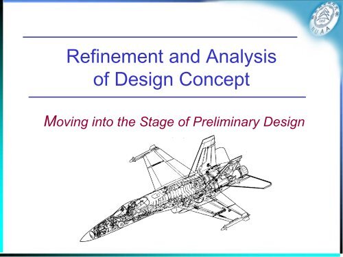
<strong>Refinement</strong> <strong>and</strong> Analysis<br />
<strong>of</strong> Design Concept<br />
Moving into the Stage <strong>of</strong> Preliminary Design
1. Specification<br />
2. Configuration A<br />
3. Flight regime / Powerplant<br />
4. Fuselage layout<br />
5. Wing configuration 1<br />
6. Lift, drag, mass<br />
7. performance<br />
8. Stage one optimization:T/Mg, mg/S<br />
8. Stage two optimization: referee design<br />
8. Configuration comparison<br />
9. Concept <strong>analysis</strong><br />
Road Map<br />
航空宇航学院<br />
Configuration B Configuration C<br />
Wing configuration 2 Wing configuration 3<br />
Aircraft Conceptual Design
Introduction<br />
航空宇航学院<br />
• We just completed the <strong>concept</strong>ual design synthesis<br />
• Now moving on to the stage <strong>of</strong> preliminary design<br />
– <strong>Refinement</strong>s<br />
• More detail parameters <strong>of</strong> the configuration<br />
• More detail <strong>and</strong> precise arrangements <strong>of</strong> the layout<br />
– Analysis<br />
• Verifying the design <strong>concept</strong> using more precise models<br />
– Optimization<br />
• Searching a optimum design with more detail parameters <strong>of</strong> the<br />
configuration using more precise models<br />
Aircraft Conceptual Design
<strong>Refinement</strong>s<br />
• Powerplant<br />
• Aerodynamic Configuration<br />
• Structure Layout<br />
• L<strong>and</strong>ing Gear<br />
• Fuselage Layout
航空宇航学院<br />
<strong>Refinement</strong>s <strong>of</strong> Powerplant<br />
• More accurate engine data<br />
– Mass data:<br />
– Size data:<br />
– Performance data: Variation <strong>of</strong> thrust <strong>and</strong> fuel consumption as<br />
function <strong>of</strong> flight speed, altitude <strong>and</strong> engine setting<br />
• How to get the data<br />
– From the engine manufactures<br />
– Using the more precise model <strong>of</strong> the engine based the engine<br />
design method<br />
• Powerplant Location<br />
– The development <strong>of</strong> the design <strong>concept</strong> now enables the question<br />
<strong>of</strong> powerplant location to be considered more precisely.<br />
Aircraft Conceptual Design
Powerplant Location<br />
• Versatility <strong>and</strong> access:<br />
航空宇航学院<br />
– As a general rule engines mounted in pods or nacelles on the<br />
outside <strong>of</strong> the aircraft are more versatile than those buried within<br />
the airframe.<br />
– It is usually possible to accommodate different engines without<br />
too much difficulty, thereby more readily h<strong>and</strong>ling upgrades or<br />
specific customer requirements.<br />
– Podded <strong>and</strong> nacelle-mounted engines are also preferable for<br />
maintenance since access is generally more direct <strong>and</strong> need not<br />
involve significant structural penalties.<br />
– Also air intakes <strong>and</strong> exhausts are usually shorter <strong>and</strong> can be<br />
more efficient.<br />
Aircraft Conceptual Design
Powerplant Location<br />
• Installation clearance<br />
航空宇航学院<br />
– As the engine dimensions are defined it is necessary to check<br />
installation clearances, such as propeller tip spacing from adjacent<br />
structure or the ground <strong>and</strong> under-wing nacelle ground clearance on<br />
a low wing aircraft.<br />
Aircraft Conceptual Design
• Safety<br />
Powerplant Location<br />
航空宇航学院<br />
– The powerplants must be positioned so that in emergency<br />
situations they do not pose a threat to the occupants <strong>of</strong> the<br />
aircraft or other safety critical components.<br />
– The major concerns are the consequences <strong>of</strong> an engine<br />
becoming detached during an emergency alighting situation<br />
or the failure <strong>of</strong> rotating components such as fan <strong>and</strong> turbine<br />
blades or discs <strong>and</strong> propeller blades.<br />
– The engines must be located such that these component<br />
failures do not present a hazard to other engines, primary<br />
structures or vital systems.<br />
Aircraft Conceptual Design
Powerplant Location<br />
• Acoustic considerations<br />
航空宇航学院<br />
– The further aft on an aircraft the engine is located the less is the<br />
noise impact upon the occupants, but this is not usually a major<br />
consideration.<br />
– Some engine positions, for example those above the wing or<br />
fuselage, reduce the noise as perceived at the ground but at the<br />
expense <strong>of</strong> powerplant efficiency.<br />
– Acoustic fatigue damage to airframe components located near the<br />
exhaust is likely to be a more important consideration.<br />
– It is especially significant for engines which employ reheat when the<br />
exhaust outlets should be behind all major airframe components.<br />
Aircraft Conceptual Design
Powerplant Location<br />
• Stability <strong>and</strong> control<br />
航空宇航学院<br />
– Lateral stability <strong>and</strong> control requirements for a multi-engined<br />
aircraft may well be dominated by the need to maintain the<br />
path <strong>of</strong> the aircraft subsequent to the failure <strong>of</strong> the most<br />
critical engine.<br />
– From this point <strong>of</strong> view wing-located powerplants should be<br />
as far inboard as allowed by other considerations.<br />
Aircraft Conceptual Design
Powerplant Location<br />
• Powerplant/airframe effciency<br />
航空宇航学院<br />
– This <strong>of</strong>ten means a compromise between engine requirements<br />
<strong>and</strong> those <strong>of</strong> the overall aerodynamics.<br />
– For example:<br />
• it may be desirable on a short take-<strong>of</strong>f propeller driven aircraft to space the<br />
engines across the wing to enhance slipstream effect upon low speed lift.<br />
• Ground clearance may suggest that large diameter power units should be<br />
mounted over the top <strong>of</strong> the wing but this can lead to a considerable loss <strong>of</strong><br />
efficiency <strong>of</strong> lift development.<br />
• In the case <strong>of</strong> buried engines the intake arrangements may have a significant<br />
effect upon powerplant efficiency <strong>and</strong> must be given careful consideration,<br />
Aircraft Conceptual Design
• Introduction<br />
<strong>Refinement</strong> <strong>of</strong> wing<br />
航空宇航学院<br />
– The <strong>analysis</strong> <strong>of</strong> the lifting characteristics <strong>of</strong> the wing dem<strong>and</strong>s a<br />
more specific consideration <strong>of</strong> both the basic aer<strong>of</strong>oil section <strong>and</strong><br />
the geometry <strong>of</strong> the high lift devices than was possible at the<br />
<strong>concept</strong>ual design stage<br />
• Airfoil selection <strong>and</strong> design<br />
– The output <strong>of</strong> the parametric <strong>analysis</strong> includes some aer<strong>of</strong>oil detail,<br />
such as the root thickness to chord ratio <strong>and</strong> the desired critical<br />
Mach number characteristics.<br />
– This information may be used in the selection <strong>of</strong> a suitable aer<strong>of</strong>oil.<br />
– The airfoil design <strong>and</strong> optimization will be introduced later.<br />
Aircraft Conceptual Design
• High lift device<br />
<strong>Refinement</strong> <strong>of</strong> wing<br />
– Leading edge high lift devices<br />
航空宇航学院<br />
• While leading edge high lift devices may be located across the greater part<br />
<strong>of</strong> the wing span, it may be necessary to accept some interruption, as for<br />
example in the region <strong>of</strong> wing-located powerplants.<br />
• Such effects should be minimised <strong>and</strong> carefully considered as the details <strong>of</strong><br />
the design are established.<br />
Aircraft Conceptual Design
<strong>Refinement</strong> <strong>of</strong> wing<br />
– The trailing edge high lift devices<br />
航空宇航学院<br />
• Generally the spanwise extent <strong>of</strong> the trailing edge high lift devices is limited<br />
by the need to provide ailerons for roll control although in some special<br />
circumstances these may be "drooped" to augment the lift.<br />
• Outboard ailerons are usually needed for low speed roll control <strong>and</strong> typically<br />
occupy 20-25% <strong>of</strong> the wing semi-span.<br />
Aircraft Conceptual Design
航空宇航学院<br />
<strong>Refinement</strong> <strong>of</strong> aerodynamics design<br />
• Control/stabilizer surface<br />
– Outer ailerons on high aspect ratio sweptback wings may<br />
introduce aeroelastic difficulties when used at high speed, <strong>and</strong> to<br />
overcome this problem alternative high speed roll control may be<br />
provided in the form <strong>of</strong> inboard ailerons or differential longitudinal<br />
controls such as tailerons.<br />
– In the case <strong>of</strong> inboard ailerons there will be an effect upon the<br />
extent <strong>of</strong> the trailing edge flaps although this may be minimised<br />
by locating the controls immediately behind powerplants.<br />
– Within some limits the effectiveness <strong>of</strong> trailing edge devices may<br />
be adjusted by variation <strong>of</strong> their chordwise extent.<br />
Aircraft Conceptual Design
航空宇航学院<br />
<strong>Refinement</strong> <strong>of</strong> control <strong>and</strong> stabiliser surfaces<br />
• The design <strong>of</strong> the control <strong>and</strong> stabiliser surfaces<br />
requires ensuring that there is:<br />
– Ability to provide the forces/moments needed to maintain the<br />
trim <strong>of</strong> the aircraft in all flight conditions.<br />
– Ability to provide control forces/moments to meet prescribed<br />
h<strong>and</strong>ling criteria, including situations in which a partial failure<br />
has occurred.<br />
– Stability in both the static <strong>and</strong> dynamic sense, or alternatively<br />
acceptable artificial damping or stability in all critical modes.<br />
Aircraft Conceptual Design
航空宇航学院<br />
<strong>Refinement</strong> <strong>of</strong> control <strong>and</strong> stabiliser surfaces<br />
• The design <strong>of</strong> the control <strong>and</strong> stabiliser surfaces is<br />
complex because <strong>of</strong> the number <strong>of</strong> separate conditions<br />
which have to be met.<br />
• Some simplifications may be made to facilitate the<br />
process during initial design work<br />
• We have presented the design methods for the<br />
longitudinal <strong>and</strong> lateral requirements respectively.<br />
• The output from these methods may then be used for<br />
a full <strong>analysis</strong>.<br />
Aircraft Conceptual Design
Structure<br />
航空宇航学院<br />
• The overall layout <strong>of</strong> the aircraft must be compatible with<br />
an efficient structure<br />
• The aerodynamic configuration must not be such as to<br />
imply an unacceptable high structure weight.<br />
• Wing structure layout<br />
– Referring to the course “ Design <strong>of</strong> Aircraft Structure”<br />
• Fuselage structure layout<br />
– Referring to the course “ Design <strong>of</strong> Aircraft Structure”<br />
Aircraft Conceptual Design
Wing structure layout<br />
航空宇航学院<br />
• Sometimes the spanwise bending <strong>and</strong> torsion requirements may<br />
be met by a single beam or spar located near to the maximum<br />
chordwise depth <strong>of</strong> the aer<strong>of</strong>oil <strong>and</strong> associated with a shear<br />
carrying leading edge, or 'D' nose, terminating at the spar.<br />
• More usually there are two or more spars located across the<br />
chord, <strong>and</strong> together with the upper <strong>and</strong> lower covers between<br />
their chordwise extremities they form a box beam which also<br />
meets the torsion requirement.<br />
• The forward <strong>and</strong> aft extremities <strong>of</strong> this beam are determined by<br />
the auxiliary lifting surfaces <strong>and</strong> ailerons.<br />
• The rearmost spar is <strong>of</strong>ten located at 60-70% <strong>of</strong> the chord,<br />
leaving room for the trailing edge surfaces<br />
Aircraft Conceptual Design
Wing structure layout<br />
航空宇航学院<br />
• The box beam also conveniently acts as integral tankage for the fuel<br />
<strong>and</strong> access panels are required for inspection purposes.<br />
• For moderate to high aspect ratio wings the box beam should be<br />
continuous across the whole span.<br />
• Large cutouts for such items as l<strong>and</strong>ing gear stowage should be<br />
outside its boundaries.<br />
• When the powerplant is buried within the fuselage <strong>and</strong> the wing is <strong>of</strong><br />
relatively low aspect ratio, it is <strong>of</strong>ten necessary to use several spanwise<br />
spars <strong>and</strong> to pass the bending loads round the fuselage by means <strong>of</strong> a<br />
series <strong>of</strong> ring frames to which the spars are connected.<br />
Aircraft Conceptual Design
航空宇航学院<br />
An example <strong>of</strong> structure layout<br />
Aircraft Conceptual Design
航空宇航学院<br />
<strong>Refinement</strong> <strong>of</strong> L<strong>and</strong>ing Gear<br />
• The main points to be investigated are<br />
– Overall layout geometry, including the number <strong>of</strong> main gear units<br />
– Number <strong>and</strong> size <strong>of</strong> the wheels/tyres<br />
– Location <strong>of</strong> suitable stowage volume<br />
– Location <strong>of</strong> suitable load attachment points.<br />
• Clearly these latter two issues are closely related to the<br />
layout <strong>of</strong> the structural members.<br />
See Addendum 1 for more detail<br />
Aircraft Conceptual Design
Fuselage Layout<br />
航空宇航学院<br />
• A more precise <strong>and</strong> detailed layout <strong>of</strong> the fuselage may<br />
now be undertaken.<br />
– Influence <strong>of</strong> the wing junction with the fuselage<br />
– L<strong>and</strong>ing gear attachment <strong>and</strong> stowage<br />
– Layout <strong>of</strong> the cockpit region, windscreen geometry, etc.<br />
– Detail <strong>of</strong> the powerplant installation<br />
– Payload detail<br />
• Doors,windows<br />
• Freight loading access <strong>and</strong> doors<br />
– Special detail considerations<br />
With an aid <strong>of</strong> CAD s<strong>of</strong>tware<br />
Aircraft Conceptual Design
Now, we embark on <strong>analysis</strong> <strong>of</strong> the more<br />
detail design using more precise models<br />
• Mass prediction<br />
• Aerodynamics <strong>analysis</strong><br />
• Structure <strong>analysis</strong><br />
• Performance <strong>analysis</strong><br />
• Stability <strong>and</strong> control <strong>analysis</strong><br />
• Cost
航空宇航学院<br />
Mass Prediction Techniques<br />
• Empirical comparisons<br />
– Predictions by direct comparison with other similar design<br />
• Empirical formulae<br />
– Derived by a statistical <strong>analysis</strong> <strong>of</strong> available information from<br />
many aircraft (see chapter 6 )<br />
• Theoretically derived formulae<br />
– Based on a simplified design <strong>of</strong> the component<br />
– See Addendum 4<br />
• Detail estimation method<br />
– Need information <strong>of</strong> the detailed component<br />
Aircraft Conceptual Design
Aerodynamic Analysis<br />
航空宇航学院<br />
• The different levels <strong>of</strong> the <strong>analysis</strong> models<br />
– Theoretical method<br />
• Aerodynamic theory + empirical data (past experience)<br />
– Numerical methods<br />
• Vortex lattice method<br />
• Panel Method<br />
• Computational Fluid Dynamics (CFD)<br />
– Experimental method<br />
• Wind tunnel tests<br />
Aircraft Conceptual Design
Aerodynamic Analysis<br />
Theoretical + empirical method<br />
C C KC<br />
D<br />
D0<br />
L<br />
0.<br />
e 1. 78(<br />
1<br />
0.<br />
045<br />
2<br />
68<br />
) <br />
k<br />
0.<br />
64<br />
1<br />
<br />
<br />
n<br />
( C S )<br />
f , i wet , i<br />
i1<br />
C <br />
C C C<br />
D0<br />
D,<br />
misc D,<br />
漏,凸 D,<br />
波<br />
Vortex lattice method<br />
S<br />
e<br />
(unswept)<br />
航空宇航学院<br />
Wind tunnel test<br />
Panel method CFD<br />
Aircraft Conceptual Design
Structure Analysis<br />
• Beam theory<br />
– Refer to the course “Structure Mechanics”<br />
• Finite Element Method (FEM )<br />
航空宇航学院<br />
Aircraft Conceptual Design
Performance Analysis<br />
航空宇航学院<br />
• Predicate a precise performance using the<br />
following upgraded information<br />
– Engine data<br />
– More precise lift <strong>and</strong> drag data<br />
– More precise mass data<br />
Performance<br />
Powerplant aerodynamics Mass<br />
Aircraft Conceptual Design
Stability <strong>and</strong> Control Analysis<br />
• Theoretical + empirical method<br />
– Referring to textbook on “Flight Dynamics”<br />
– DatCom s<strong>of</strong>tware<br />
– AAA s<strong>of</strong>tware<br />
• Numerical method<br />
– Vortex lattice<br />
– Panel method<br />
– CFD<br />
• Wind tunnel test<br />
航空宇航学院<br />
Aircraft Conceptual Design
Cost Analysis<br />
航空宇航学院<br />
Cost estimation should base on a<br />
comparative rather than absolute value<br />
Aircraft Conceptual Design
航空宇航学院<br />
Different Cost Meanings<br />
• Selling cost<br />
– driven by market forces<br />
• First cost<br />
• Operating costs<br />
• Lift cycle costs<br />
Aircraft Conceptual Design
• What is first cost<br />
First cost<br />
航空宇航学院<br />
– The sum <strong>of</strong> the actual cost <strong>of</strong> making the aircraft <strong>and</strong> the<br />
share <strong>of</strong> the development costs allocated to it.<br />
• First cost is difficult to be predicted at the aircraft<br />
<strong>concept</strong>ual design<br />
– Simple cost models are usually based on aircraft volume<br />
<strong>and</strong>/or mass <strong>and</strong> derived empirically from past experience.<br />
– First cost is not a very suitable criterion for project<br />
optimization.<br />
Aircraft Conceptual Design
Operating costs<br />
• Operating costs are split into two categories<br />
– Indirect costs<br />
航空宇航学院<br />
• Independent <strong>of</strong> the characteristics <strong>of</strong> a given aircraft <strong>and</strong><br />
represent the overall costs <strong>of</strong> the operation <strong>of</strong> the airline.<br />
– Direct Operating Costs (DOC)<br />
• The initial purchase price<br />
• Insurance<br />
• Crew costs<br />
• Engineering replacement items<br />
• Maintenance<br />
• Operational charges<br />
• Fuel <strong>and</strong> other expendable items<br />
Aircraft Conceptual Design
航空宇航学院<br />
Direct Operating Costs (DOC)<br />
• DOC is a better criterion for optimization<br />
than first cost.<br />
• DOC is difficult to be calculated.<br />
• There is a close relationship between<br />
direct operating costs <strong>and</strong> aircraft mass.<br />
Aircraft Conceptual Design
Life cycle costs<br />
• Life Cycle Costs (LCC) covers:<br />
– Design <strong>and</strong> development <strong>of</strong> the type<br />
– Procurement <strong>of</strong> the aircraft<br />
– Cost <strong>of</strong> operations<br />
– Final cost disposal <strong>of</strong> the aircraft<br />
航空宇航学院<br />
• LCC is a relevant criterion for optimization, but difficult to be<br />
estimated<br />
– Recourse may have to made to comparisons on relative basis.<br />
– LCC <strong>of</strong> military aircrafts is more or less directly proportional to mass<br />
<strong>and</strong> maximum operating speed for Mach 1.3 or below.<br />
Aircraft Conceptual Design
Introduction to AAA s<strong>of</strong>tware<br />
A s<strong>of</strong>tware for <strong>analysis</strong> <strong>of</strong> aircraft preliminary design
航空宇航学院<br />
Aircraft Conceptual Design
Finally, we use optimization to<br />
search a better design<br />
Introduction to Multidisciplinary Design Optimization (MDO)<br />
A advanced method for aircraft preliminary design optimization
(MDO) Framework<br />
气动(CFD)<br />
外形(CAD)<br />
隐身<br />
结构(FEM)<br />
协调(MDO方法)<br />
中心数据库<br />
设计过程监控<br />
性能<br />
重量重心<br />
操稳<br />
发动机特性<br />
航空宇航学院<br />
Aircraft Conceptual Design
Output <strong>of</strong> the Preliminary Design
A detail configuration<br />
728JET 三维外形<br />
航空宇航学院<br />
Aircraft Conceptual Design
Fwd FA Seat<br />
(View Fwd)<br />
航空宇航学院<br />
A detail Fuselage Layout<br />
728JET <strong>and</strong> 928JET Galleys <strong>and</strong> Wardrobes<br />
Forward Galley<br />
(View Fwd)<br />
Forward Wardrobe<br />
(View Aft)<br />
Forward Lavatory<br />
(View Aft)<br />
Rear Galley<br />
(View Aft)<br />
Flexible Design to Meet Highest Customer Requirements.<br />
Rear Lavatory<br />
(View Aft)<br />
Aircraft Conceptual Design
A overall layout (F-16)<br />
航空宇航学院<br />
Aircraft Conceptual Design
A overall layout (AD-400)<br />
航空宇航学院<br />
Aircraft Conceptual Design

![Introduction to RF Stealth [Book Review] - Antennas and ...](https://img.yumpu.com/16857890/1/190x245/introduction-to-rf-stealth-book-review-antennas-and-.jpg?quality=85)