FASTCAMERA SERIES - Alacron, Inc.
FASTCAMERA SERIES - Alacron, Inc.
FASTCAMERA SERIES - Alacron, Inc.

You also want an ePaper? Increase the reach of your titles
YUMPU automatically turns print PDFs into web optimized ePapers that Google loves.
<strong>FASTCAMERA</strong> <strong>SERIES</strong><br />
<br />
<br />
<br />
<br />
<br />
<br />
<br />
<br />
<strong>FASTCAMERA</strong>13<br />
USER’S MANUAL<br />
30002-50013
COPYRIGHT NOTICE<br />
Copyright © 2003 by FastVision, LLC.<br />
All rights reserved. This document, in whole or in part, may not be copied, photocopied,<br />
reproduced, translated, or reduced to any other electronic medium or machine-readable form<br />
without the express written consent of FastVision, LLC.<br />
FastVision makes no warranty for the use of its products, assumes no responsibility for any error,<br />
which may appear in this document, and makes no commitment to update the information<br />
contained herein. FastVision, LLC. retains the right to make changes to this manual at any time<br />
without notice.<br />
Document Name: FastCamer13 User’s Manual<br />
Document Number: 30002-50013<br />
Revision History: 1.0 January 20,2003<br />
1.1 March 26,2003<br />
1.2 March 30,2003<br />
1.3 April 9, 2003<br />
Trademarks:<br />
FastVision® is a registered trademark of FastVision, LLC..<br />
Channel Link is a trademark of National Semiconductor.<br />
3M is a trademark of 3M Company<br />
MS DOS® is a registered trademark of Microsoft Corporation<br />
SelectRAM is a trademark of Xilinx <strong>Inc</strong>.<br />
Solaris is a trademark of Sun Microsystems <strong>Inc</strong>.<br />
Unix® is a registered trademark of Sun Microsystems <strong>Inc</strong>.<br />
Virtex is a trademark of Xilinx <strong>Inc</strong>.<br />
Windows, Windows 95, Windows 98, Windows 2000, Windows NT, and<br />
Windows XP are trademarks of Microsoft<br />
All trademarks are the property of their respective holders.<br />
FastVision, LLC.<br />
131 Daniel Webster Highway, #529<br />
Nashua, NH 03060<br />
USA<br />
Telephone: 603-891-4317<br />
Fax: 603-891-1881<br />
Web Site:<br />
http://www.fast-vision.com/<br />
Email:<br />
sales@fast-vision.com, or support@fast-vision.com<br />
3
TABLE OF CONTENTS<br />
Copyright Notice …………………………………………………………………………………..3<br />
Table of Contents ………………………………………………………………………………... 5<br />
1. INTRODUCTION .................................................................................................................7<br />
2. FEATURES AND SPECIFICATIONS <strong>FASTCAMERA</strong> 13..................................................7<br />
3. POWER REQUIREMENTS ...............................................................................................11<br />
4. TIMING ..............................................................................................................................11<br />
5. TRIGGER MODES ............................................................................................................11<br />
6. CAMERA DATA FLOW ....................................................................................................13<br />
7. THE STANDARD CAMERA FUNCTIONALITY ...............................................................13<br />
8. EXPOSURE CONTROL....................................................................................................13<br />
9. PIXEL GAIN AND OFFSET ..............................................................................................15<br />
10. MEMORY OPTION (MEM?)..............................................................................................15<br />
11. LOOKUP TABLE OPTION (LUT?)...................................................................................16<br />
12. DATA FORMAT FUNNEL.................................................................................................16<br />
13. INTERNAL CAMERA MEMORY ......................................................................................17<br />
14. USB CAMERA OPTION ...................................................................................................22<br />
15. CAMERA CONTROL PROGRAM ....................................................................................23<br />
16. APPLICATION ENVIRONMENTS ....................................................................................24<br />
17. TROUBLESHOOTING ......................................................................................................28<br />
18. FASTVISION TECHNICAL SUPPORT.............................................................................29<br />
5
1. INTRODUCTION<br />
The FastCamera13 is a 1.3 megapixel CMOS camera with internal memory and FPGA’s that<br />
enable it to do real-time processing. Thus it is what one would term a “smart” camera. The<br />
standard programming that is supplied with the base camera forms the basis of the most used<br />
and demanded function for data processing. It is expected that each customer may wish to<br />
customize this programming for its use. This can be achieved by purchasing additional IP from<br />
FastVision or in-house development. Inquires or discussions are always welcome<br />
2. FEATURES AND SPECIFICATIONS <strong>FASTCAMERA</strong> 13<br />
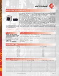
The block diagram below shows the major subsystems in the camera. The camera is designed to<br />
support many different applications by customization of the programmable logic in the camera.<br />
FastVision or the Customer can customize the size and content of the FPGAs and memory in the<br />
camera to contain many different features, processing algorithms, and storage schemes. This<br />
manual discusses the ‘Standard’ version of the cameras. Customization of the FPGAs, in the<br />
camera, requires significant support from FastVision, please contact FastVision for a quote, for<br />
the development tools and support.<br />
1.3 MPixel<br />
CMOS<br />
Sensor<br />
XC2VX000<br />
FPGA<br />
1-8 Million Gates<br />
2-4 MB<br />
SRAM<br />
FPGA<br />
Boot<br />
Flash<br />
Memory<br />
Controller<br />
FPGA<br />
(Optional)<br />
128-1000MB<br />
DDRAM<br />
200 MHz<br />
7<br />
Camera<br />
Control<br />
LVDS<br />
Link Receivers<br />
(CC1-4)<br />
(Async Serial)<br />
Three 85 MHz<br />
Channel Link<br />
Drivers<br />
66 MHz<br />
Channel<br />
Link Driver<br />
66 MHz<br />
Channel<br />
Link Driver<br />
Power<br />
Supply<br />
• The FastCamera13 uses a 1280H x 1024V (1.3 megapixel) CMOS digital image<br />
sensor capable of 500 frames/second operation at full resolution<br />
• 1280H x 1024V image resolution<br />
CC1<br />
CC2<br />
CC3<br />
CC4
• 12-micron-square active-pixel photodiodes<br />
• 500+ frames per second, progressive-scan<br />
• At full resolution, frame rate can go up to 500,000 fps at 1 x 1280pixels<br />
• Monochrome or color (Bayer Pattern)<br />
• Ten (10) parallel output ports<br />
• Photobit® TrueColorTM Image Fidelity<br />
• On-chip TrueBit® Noise Cancellation<br />
• On-chip 10-bit analog-to-digital converters<br />
• FPGA and memory-based configurable interface formats and onboard<br />
processing<br />
• Supported by a full range of software tools<br />
• Binning in order to achieve increased sensitivity at full frame rates<br />
• Optional SRAM for ultra fast processing<br />
• Optional additional DDRAM and increased FPGA size for additional processing<br />
capability<br />
• Trigger-able global electronic shutter (sync./async. modes)<br />
• C holder mount (F with adaptor)<br />
2.1 IMAGE SENSOR SPECIFICATIONS:<br />
• Uses Micron Imaging's MI-MV13 sensor<br />
• 1280 x 1024 x 8 bits @ 500 fps (10 bits 400 fps)<br />
• 15.36 mm x 12.29 mm active area<br />
• 12-micron square active pixels<br />
• 40% Fill Factor<br />
• Monochrome or color (Bayer Pattern)<br />
• On-chip Noise Cancellation<br />
• Dynamic range 59 db<br />
• Monochrome: 1000 bits per lux-second @ 550 nm<br />
• Shutter 99.9% efficiency<br />
8
132mm<br />
• Noise 58 db (10 bit mode lowest sensor gain setting, nominal pixel of 512<br />
counts)<br />
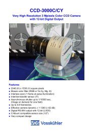
2.3 Physical Specifications<br />
FastCamera13<br />
Side View<br />
FastCamera13<br />
Bottom View<br />
12.7mm<br />
<strong>FASTCAMERA</strong>13 CASE AND<br />
MOUNTING DIMENSIONS<br />
0 ref<br />
7mm<br />
0 ref<br />
FastCamera13<br />
Front View<br />
12.7mm<br />
9<br />
39.5mm<br />
79.0mm<br />
74.0mm<br />
39.5m<br />
m<br />
0 ref<br />
0 ref<br />
7mm<br />
FastCamera13<br />
Back Panel<br />
P2<br />
J2<br />
J3
2.4 Connectors<br />
2.4.1 Power Connector HR10A-10R-12PB<br />
Pin Function<br />
1 Ground<br />
2 +5 Volts<br />
3 Ground<br />
4 Reserved for application dependent I/O<br />
5 Ground<br />
6 +5 Volts<br />
7 Reserved for application dependent I/O<br />
8 Ground<br />
9 +5 Volts<br />
10 Reserved for application dependent I/O<br />
11 +5 Volts<br />
12 Reserved for application dependent I/O<br />
2.4.2 Data Connector J2<br />
Pin Signal Pin Signal<br />
1 Ground 14 Ground<br />
2 CL1_TXOUT0N 15 CL1_TXOUT0P<br />
3 CL1_TXOUT1N 16 CL1_TXOUT1P<br />
4 CL1_TXOUT2N 17 CL1_TXOUT2P<br />
5 CL1_TXCLKOUTN 18 CL1_TXCLKOUTP<br />
6 CL1_TXOUT3N 19 CL1_TXOUT3P<br />
7 SERTCP 20 SERTCN<br />
8 CC1N 21 SERTFGP<br />
9 CC2P 22 CC1P<br />
10 CC3N 23 CC2N<br />
11 CC4P 24 CC3P<br />
12 SERTFGN 25 CC4N<br />
13 Ground 26 Ground<br />
2.4.3 Data Connector J3<br />
Pin Signal Pin Signal<br />
1 Ground 14 Ground<br />
2 CL2_TXOUT0N 15 CL2_TXOUT0P<br />
3 CL2_TXOUT1N 16 CL2_TXOUT1P<br />
4 CL2_TXOUT2N 17 CL2_TXOUT2P<br />
5 CL2_TXCLKOUTN 18 CL2_TXCLKOUTP<br />
6 CL2_TXOUT3N 19 CL2_TXOUT3P<br />
7 Application Specific 20 Application Specific<br />
I/O (P)<br />
I/O (N)<br />
8 CL3_TXOUT0N 21 CL3_TXOUT0P<br />
9 CL3_TXOUT1N 22 CL3_TXOUT1P<br />
10 CL3_TXOUT2N 23 CL3_TXOUT2P<br />
11 CL3_TXCLKOUTN 24 CL3_TXCLKOUTP<br />
12 CL3_TXOUT3N 25 CL3_TXOUT3P<br />
10
13 Ground 26 Ground<br />
3. POWER REQUIREMENTS<br />
Power requirements are a strong function of the application, Camera is 15 Watts worst case, 5 to<br />
10 Watts typical. Low noise +5 Volt input recommended. Internally the camera has high<br />
frequency switching supplies that convert the 5 volt input to 3.3, 2.5 and 1.8 volts.<br />
4. TIMING<br />
Camera Clock is configurable from 25 to 85 MHz depending on the application.<br />
Pixel data is valid when LVAL, FVAL and DVAL are true.<br />
Minimum two clocks LVAL and FVAL inactive between lines and frames.<br />
CC4 reserved for application specific needs.<br />
5. TRIGGER MODES<br />
Trigger modes are selected by serial commands.<br />
Free Running, camera generates frames without triggers.<br />
CC1 Positive edge triggered.<br />
CC1 When active, expose, falling edge reads out the sensor.<br />
Sensor readout can be in parallel with exposure.<br />
The camera can be read out with 1,2, or 3 camera links, the serial port (for the really patient), or<br />
via the USB port. Only image data from the selected ROI is sent. The camera can be configured<br />
to read out when the image is taken, to read out from memory on serial command or the CC2<br />
positive edge.<br />
Data formats supported:<br />
Mode Camera Link Format<br />
MSB -------------------------------- LSB<br />
11<br />
Read Out Mode<br />
0 CL1_A[7:0] Single tap 8 bits<br />
(Basic) (default)<br />
1 CL1_B[1:0],CL1_A[7:0] Single tap 10 bits<br />
(Basic)<br />
2 CL1_A[7:0] even pixels (0,2,...)<br />
Two Taps 8 bits<br />
CL1_B[7:0] odd pixels (1,3,...)<br />
(Basic)<br />
3 CL1_B[1:0],CL1_A[7:0] even<br />
Two Taps 10 bits<br />
CL1_B[5:4],CL1_C[7:0] odd<br />
4 CL1_A[7:0] Red, Y<br />
CL1_B[7:0] Green, U<br />
CL1_C[7:0] Blue, V<br />
5 CL1_B[1:0],CL1_A[7:0] Red, Y<br />
CL1_B[5:4],CL1_C[7:0] Green, U<br />
CL2_D[1:0],CL2_C[7:0] Blue, V<br />
6 CL1_B[7:0],CL1_A[7:0]<br />
CL1_A[4:0] Red, U<br />
CL1_B[2:0],CL1_A[7:5] Green, Y<br />
CL1_B[7:3] Blue V<br />
(Basic)<br />
Three Taps 8 bits<br />
(Color) (Basic)<br />
Three Taps 10 bits<br />
(Color) (Medium)<br />
One tap 16 Bits<br />
RGB565 (Basic)
7 CL1_A[7:0] pixels 4*n+0<br />
CL1_B[7:0] pixels 4*n+1<br />
CL1_C[7:0] pixels 4*n+2<br />
CL2_A[7:0] pixels 4*n+3<br />
8 CL1_B[1:0],CL1_A[7:0] 4*n+0<br />
CL1_B[5:4],CL1_C[7:0] 4*n+1<br />
CL2_C[1:0],CL2_B[7:0] 4*n+2<br />
CL2_C[4:5],CL2_A[7:0] 4*n+3<br />
9 CL1_A[7:0] pixels 5*n+0<br />
CL1_B[7:0] pixels 5*n+1<br />
CL1_C[7:0] pixels 5*n+2<br />
CL2_A[7:0] pixels 5*n+3<br />
CL2_B[7:0] pixels 5*n+4<br />
10 CL1_B[1:0],CL1_A[7:0] 5*n+0<br />
CL1_B[5:4],CL1_C[7:0] 5*n+1<br />
CL2_C[1:0],CL2_B[7:0] 5*n+2<br />
CL2_C[4:5],CL2_A[7:0] 5*n+3<br />
CL3_C[1:0],CL3_B[7:0] 5*n+4<br />
11 CL1_A[7:0] R even<br />
CL1_B[7:0] G even<br />
CL1_C[7:0] B even<br />
CL2_A[7:0] R odd<br />
CL2_B[7:0] G odd<br />
CL2_C[7:0] B odd<br />
12 CL1_B[1:0],CL1_A[7:0] R even<br />
CL1_B[5:4],CL1_C[7:0] G even<br />
CL2_C[1:0],CL2_B[7:0] B even<br />
CL2_C[4:5],CL2_A[7:0] R odd<br />
CL3_C[1:0],CL3_B[7:0] G odd<br />
CL3_C[5:4],CL3_A[7:0] B odd<br />
13 CL1_A[7:0] 8*n+0<br />
CL1_B[7:0] 8*n+1<br />
CL1_C[7:0] 8*n+2<br />
CL2_A[7:0] 8*n+3<br />
CL2_B[7:0] 8*n+4<br />
CL2_C[7:0] 8*n+5<br />
CL3_A[7:0] 8*n+6<br />
CL3_B[7:0] 8*n+7<br />
14 CL1_B[1:0],CL1_A[7:0] 8*n+0<br />
CL1_B[5:4],CL1_C[7:0] 8*n+1<br />
CL2_B[1:0],CL2_A[7:0] 8*n+2<br />
CL2_B[5:4],CL2_C[7:0] 8*n+3<br />
CL3_B[1:0],CL3_A[7:0] 8*n+4<br />
CL3_B[5:4],CL3_C[7:0] 8*n+5<br />
CL2_FVAL,CL2_LVAL,CL2_SP,CL1_SP,<br />
CL1_B[7:6],CL1_B[3:2] 8*n+6<br />
CL3_FVAL,CL3_LVAL,CL1_DVAL,CL3_SP<br />
,<br />
CL2_B[7:6],CL2_B[3:2] 8*n+7<br />
12<br />
Four Taps 8 bits<br />
(Medium)<br />
Four Taps 10 bits<br />
(Medium)<br />
Five Taps 8 bits<br />
(Medium)<br />
Five Taps 10 bits<br />
(Full)<br />
Six Taps 8 bits (Color)<br />
(Medium)<br />
Six Taps 10 bits<br />
(Color) (Full)<br />
Eight Taps 8 bits (Full)<br />
Eight Taps 10 bits<br />
(Full)<br />
254 NA Use Serial Port<br />
255 NA Use USB<br />
Other modes are possible with custom FPGA configurations purchased from FastVision or<br />
developed in-house.
6. CAMERA DATA FLOW<br />
Sensor<br />
Exposure<br />
Control<br />
CC1<br />
Trigger<br />
Frame<br />
Capture<br />
Frame<br />
Rate<br />
And<br />
Exposure<br />
Serial<br />
Settings<br />
DDR<br />
Tables<br />
By Pixel<br />
Gain &<br />
Offset<br />
ROI<br />
Serial<br />
Settings<br />
Mem LUT<br />
128-1000MB<br />
DDR<br />
Memory<br />
CC3<br />
Clear<br />
Memory<br />
Or<br />
Stop Filling<br />
CC2<br />
Read<br />
Memory<br />
SRAM<br />
LUT<br />
13<br />
Data<br />
Format<br />
Funnel<br />
Serial<br />
Settings<br />
Camera<br />
Links<br />
DDR Memory can be organized as a FIFO or as a circular buffer. CC3 is used to clear the<br />
memory (FIFO) or stop filling the memory (circular buffer). CC2 is used to read the top most<br />
image from memory (FIFO) or to read the oldest non-read image from memory (Circular buffer).<br />
The LUT converts the input pixels (10 Bits) to the output pixel size (8 or 10 Bits). These tables<br />
can also be used to improve the linearity of the sensor, or to set the gamma of the camera.<br />
DDR Memory can be used for image averaging. In this mode Images are summed into a 32 bit<br />
per pixel buffers, which can be read out at any time (CC2) and/or cleared (CC3).CC1,CC2, and<br />
CC3 can be replaced by Serial Commands, or can be always enabled or disabled, for free<br />
running operation.<br />
7. THE STANDARD CAMERA FUNCTIONALITY<br />
The ‘Standard’ Camera is a set of FPGAs designed to support most of the typical uses of the<br />
camera. It is a good starting point for modifications. This design is copyrighted IP from FastVision<br />
and forms the reference design, which is available from FastVision for use only with the<br />
FastCamera13.<br />
8. EXPOSURE CONTROL<br />
The frame rate and exposure can be controlled in several ways.<br />
Free Running Mode<br />
CC1 positive(or negative) edge triggered<br />
CC1 exposure control (positive or negative level triggered)
In Free running mode the frame rate and exposure time is set via the serial port and the camera<br />
acquires images without further outside control. Frame readout occurs as fast as the selected<br />
output format can support.<br />
In CC1 edge triggered mode the camera is triggered by the selected edge polarity to expose for<br />
the time selected by the serial setting. Each edge of the CC1 input will cause the acquisition of an<br />
image. If CC1 is toggled faster then the exposure and readout rate allows, the additional triggers<br />
are ignored. Frame readout may overlap exposure. The FastCamera 13 has both a rolling shutter<br />
and a full frame shutter. The shutter speed granularity is approximately 2 microseconds. Finer<br />
resolutions are possible by lengthening the line time, and slowing down the line rate. The shortest<br />
supported exposure time is 2 microseconds.<br />
In CC1 level triggered mode the exposure is set by the active time of the CC1 input. When CC1<br />
is asserted (programmable level high or low) the sensor is reset and integration begins. When<br />
CC1 is de-asserted the sensor is read out.<br />
8.1 Rolling shutter<br />
The FastCamera 13 supports rolling shutter mode. The rolling shutter allows the camera<br />
to operate faster, by resetting each line a programmable delay (the exposure time) before<br />
it is read out. This CMOS sensor use photo diodes as the active elements of the sensor.<br />
When an exposure is started the diodes are emptied out by a reset process, which clears<br />
all the stored charge from each diode. This reset process starts the exposure for a<br />
particular pixel. After the exposure is complete, the charge in the photo diode is read out<br />
to an amplifier and converter section in the sensor. This readout process also resets the<br />
charge in the diode.<br />
All the pixels in a line are readout and reset, or just reset at the same time. The rolling<br />
reset process takes advantage of the readout process to set the exposure. When the<br />
sensor is read out each line in turn is dumped into the converters to read out all the pixels<br />
in a line. The sensor contains separate amplifiers and converters for each column in the<br />
sensor (for the FastCamera 13 that is 1280 converters!). At the same time a line is read<br />
out and reset from the sensor, a different line can be reset. By selecting the line to be<br />
reset, to be a line to be read out and reset in the near future, the exposure time is set to<br />
the number of line times between the current line, and the future line being reset.<br />
While this process allows exposure to occur while frame data is being read out, it is at a<br />
price. If your light source is continuous, you will see a compression or extension of a<br />
moving object that moves in the opposite or same direction as the readout. Typically this<br />
compression is only apparent at very high frame speeds, and / or object speeds. If your<br />
light source is a flash the compression will not occur as you can make sure all the lines<br />
are exposing, before the flash.<br />
The fastest a line can be read out from the sensors is in the time it takes for the<br />
converters to convert the charge from the photodiodes, into digital values. In the MV13<br />
sensor this is 132 clocks. In the standard camera the sensor clock rate is 66.66 MHz, this<br />
means the fastest the lines can be sampled is 1.98 microseconds per line. During this<br />
time a full line can be read out in the FastCamera 13 (1280 pixels). (Strictly speaking the<br />
converter time is 128 clocks, but there are additional overheads in reading out the line<br />
which brings this time to 132, please see the data sheets for the sensors for the details.)<br />
The sensor can not be read out faster than 1.98 microseconds per line.<br />
8.2 Full Frame shutter<br />
The sensor in the FastCamera13 allows an additional mode of operation, which is the<br />
Full Frame shutter. During the last half of a line readout cycle, the whole sensor can be<br />
reset, and integration started. During the last half of a following line (at least one) the<br />
whole sensor can stop integration. When integration is stopped the charge stored in the<br />
photodiodes is transferred to an array of storage elements, for eventual readout of the<br />
14
sensor. It takes 64 clocks for the sensor to reset, or about one microsecond. Shutter<br />
speeds are thus fixed at multiples of the line readout rate or 1.98 microseconds, or longer<br />
if the line time is increased. Further the shortest shutter speed is 1.98 microseconds.<br />
8.3 Shutter Speeds<br />
The granularity of the shutter speed at the highest readout rate possible is 1.98<br />
microseconds. This is not the whole story though. You may lengthen the line time by<br />
programming the clocks per line register (see serial command 0x04 below). By slowing<br />
down the line rate, you can dial the shutter speed (at the cost of maximum frame rate), to<br />
any time above 132 clocks. So to get a shutter speed of 3.0 microseconds you would set<br />
the clocks per line to 200 clocks. The highest full frame readout rate would be, 325<br />
frames per second.<br />
9. PIXEL GAIN AND OFFSET<br />
The offset and gain of each pixel can be calibrated by setting the pixel gain and offset arrays in<br />
the DDR memory of the camera. It is a good idea to do this as the large number of converters,<br />
need to be calibrated for best results. Note: only the pixels in the selected ROI are processed<br />
(see serial commands 0x02 and 0x03).<br />
The offset table is set by taking several images with no light input, averaging them and uploading<br />
them to the offset (or dark field) table. These values are subtracted from the sensor pixel values<br />
(clipped so less than zero values are zero), before applying the gain table values. The gain table<br />
values are obtained by taking a defocused image of a uniform object, with enough light to get to<br />
75% of saturation at most on the brightest point in the image. Using the resulting image gain<br />
values are computed (in the simplest case the pixel values and the ratio with 75% of full scale<br />
(191 (8 bit) or 768 (10 bits)) determines the gain.)<br />
Note: It is assumed that you are trying for a uniformly lit field of view (i.e. a Flat Field). It is<br />
important that you have as nearly as is practical, a uniform field of light, as large or small gain<br />
values can introduce significant artifacts in your images.<br />
The gain table contains 8 bit values, which are formatted unsigned 1.7 format, that is one binary<br />
digit followed by 7 fractional digits. This makes the range of gains 1.992 down to 0.00390625.<br />
The equation for the pixel gain and offset is:<br />
CP[i,j] = Saturate((2*Gain[i,j]/256)* Clip (P[i,j] – Offset[i,j]))<br />
CP = Corrected Pixel<br />
P = Raw sensor Pixel<br />
Clip = 0 if P[i,j]-Offset[i,j] is negative, otherwise its P[i,j]-Offset[i,j].<br />
Saturate = FullScale if its input is greater than or equal to FullScale, other wise it is it’s input<br />
alue.<br />
FullScale = 255 for 8 bit pixels 1023 for 10 bit pixels.<br />
10. MEMORY OPTION (MEM?)<br />
The camera has 120 MB (or more) memory, which can be used to store images, and do<br />
averaging. Each mode of operation is explained in the following sections. If the memory option is<br />
enabled, then sensor data goes to memory instead down stream.<br />
15
10.1 FIFO memory mode<br />
In this mode memory is used as a first in first out memory (FIFO). The memory fills with<br />
images, until it is full, and then stops filling. At any time the user may request an image<br />
from the FIFO with CC2, or via a serial command. This will make room for a new image,<br />
which will be filled as soon as one is collected. This mode is typically used by systems<br />
that can accept images in bursts, but can not accept a continuous stream of images. For<br />
example your system might take 8 images very fast and then read them out at a slower<br />
rate (via a single camera link for example), your average frame rate is slow, but your<br />
peak rate is high. If the host activates CC2 (or sends the serial command), it can cause<br />
the next image to be read out when it comes in (pre-trigger the readout).<br />
10.2 Circular buffer memory mode<br />
In this mode the memory is used as a circular buffer. Each time an image is presented to<br />
the memory it is stored over-writing the oldest image in the buffer. When CC2 goes active<br />
(or via a serial command), the filling operation stops, after a selected number of frames<br />
are added to the memory buffer (delayed trigger).<br />
After the memory image collection stops, each time CC2 toggles (or by serial command)<br />
the oldest remaining image is sent to the host. After the first CC2 is sent the host may<br />
send the next CC2 right away it does not have to wait for the filling to finish. Each image<br />
will be sent to the host as it becomes available. After the memory is full the camera will<br />
not accept any more images until it is read out or reset via CC3 (or serial command). If<br />
the host is draining images as fast as they are coming in the image capture will never<br />
stop. A reset (CC3) is required to re-arm the trigger and delay process.<br />
10.3 Image summing memory mode<br />
In this mode the memory is divided up into buffers the size of the selected ROI, but with<br />
32 bit values. Each time an image is added to memory, it is added to the current average<br />
buffer. When a programmed count of images is exceeded, the system advances to the<br />
next buffer. When all the buffers are full, the system stops until it is read out (CC2) or<br />
reset (CC3). Note: as each buffer is read out (CC2) it is reset. If the host reads out the<br />
buffers faster than they are collected, image collection will not stop. For example you<br />
can program the camera to total 10 images in each buffer, before passing it to the host.<br />
The host triggers the readout via CC2 (or serial command).<br />
The CC2 trigger may be sent at any time, the camera will provide a total buffer when it<br />
becomes available.<br />
11. LOOKUP TABLE OPTION<br />
If the lookup table option is enabled, the image data from up stream is passed through a lookup<br />
table. This applies a point transformation to each pixel value, producing 10 bit results, from the 8<br />
or 10 bit input. 32 Bit totals bi-pass the block. (Or better you should not enable this block if you<br />
are doing image totaling, as it will only operate on the lower 10 bits of the total.)<br />
12. DATA FORMAT FUNNEL<br />
The data format funnel takes the image data and parcels it out the camera links (or USB) as<br />
selected by the Format Funnel mode. If 8 bit data is selected the upper 8 bits of each pixel is<br />
sent. (Note if you don’t like that use the LUT to change this behavior).<br />
32 Bit data total buffers are sent as 8 bit data in little endian (that is least significant byte first).<br />
16
13. INTERNAL CAMERA MEMORY<br />
The camera contains at least 128 MB of internal memory which can be expanded to 1000 MB,<br />
which can be used to FIFO the input images, to allow burst exposure, and slow readout<br />
operation. Only the image data in the selected ROI is stored. A serial command or the positive<br />
edge of CC3 can be used to clear FIFO memory.<br />
In addition the Camera contains LUTs for conversion from 8 to 10 bit data which can be uploaded<br />
via the serial port.<br />
13.1 Serial Commands<br />
The following text will discuss the command and control commands to and from the<br />
FastCamera40 via the Serial Interface.<br />
For those commands that have multiple bytes of data associated with them the protocol<br />
would be:<br />
…..<br />
In this example the command was 0x01 for configure DAC’s the 3 bytes of length are<br />
necessary to accommodate being able to program the DATA FPGA via the Serial<br />
Interface. In this instance the length would total 32 bytes. 32 bytes of data would follow.<br />
The receiving machine will not go back to its idle state until 32 bytes of data are<br />
transferred across the serial interface. The following table lists the commands and their<br />
encoding:<br />
13.2 0x00 Serial Command<br />
Use this to reset the serial interface. If you send zero over and over until the camera<br />
sends a ‘?’ (0x3f) you will be back in sync without effecting the camera state.<br />
13.3 0x01 ADC settings Serial Command<br />
If you need to adjust the control voltages of the sensor, then use this command. Note:<br />
FastVision does NOT support using this command, if you change these values from the<br />
factory values, the sensor will not work right and your image quality will be poor. So if you<br />
don’t know what your doing don’t mess with this. If you mess with this, just power off the<br />
camera and power it on again, and you will be out of trouble.<br />
13.4 0x02 and 0x03 ROI Serial Commands<br />
These commands set the start and end line (0x02) and the starting and ending column<br />
0x03) of the sensor, read out and defines the size of the image. If you want the highest<br />
possible frame rate, keep the last column in your ROI less than 2048 (40). This is not an<br />
issue on the FastCamera13.<br />
13.5 0x04 Line Length Serial Command<br />
This sets the number of pixel clocks per line. If you are using the full sensor on the<br />
FastCamera40 this must be greater than or equal to 153, or 132 on the FastCamera13.<br />
Set this to larger values to slow the data rate from the camera or to get finer control of the<br />
exposure.<br />
17
13.6 0x05 Exposure Time Serial Command<br />
This is the exposure time in pixel clocks. For the standard camera this is 1/66.66 MHz<br />
steps or 15 ns steps. (Sorry it’s too hard to divide in the camera.) This must be greater<br />
than the line time (that is the content of register 0x04). Default value is 1,066,666 (16<br />
msec).<br />
13.7 0x06 Exposure delay Serial Command<br />
This sets the frame rate. The exposure time plus the exposure delay is the frame rate.<br />
This is only used in free running mode. Set to 5,600,000 by default (10 frames per<br />
second).<br />
Note: Frame Rate = 1.0 / (15ns * (reg(5)+reg(6)))<br />
13.8 0x07 Readout Image Serial Command<br />
This command simulates an activation of CC2. See above for it’s effect, but it mostly<br />
causes a stored image to be sent to the host.<br />
13.9 0x08 Reset Memory Serial Command<br />
This command simulates an activation of CC3. See above for it’s effects, but it mostly<br />
erases or resets the image memory.<br />
13.10 0x09 Set Data Funnel mode Serial Command<br />
This sets the Data-Readout-Mode, see the section above, for the values.<br />
13.11 0x10 Trigger Image Capture Serial Command<br />
This simulates an activation of CC1. See above for it’s effect, but it mostly just causes an<br />
image to be taken from the sensor, and sent to the host, or memory.<br />
13.12 0x20 Set Trigger Mode Serial Command<br />
This allows you set the trigger mode (CC1), the options are free run, CC1 edge or CC1<br />
level. See the section on exposure above.<br />
13.13 0x30 Write Flash Memory Serial Command<br />
This allows the user to data to flash memory. This command is disabled in the standard<br />
camera. The Flash memory holds the FPGA programs, and other values needed to make<br />
the camera operate. Should you wish to store some data in the Flash there is room. For<br />
more details contact FastVision.<br />
13.14 0x31 Read Flash Memory Serial Command<br />
This allows the user to read back what is in flash in the camera. This command is not<br />
disabled, so if you like read it out. If you want to understand its content please contact<br />
FastVision for details.<br />
13.15 0x40 Load the Data FPGA Serial Command<br />
This command allows custom FPGA code to be uploaded to the camera. In situations<br />
where a user has more than one set of IP for use with the camera this command can be<br />
used to upload the FPGA. Note this can take 5 minutes via the serial port at 115K baud.<br />
18
13.16 Other Serial Commands<br />
See the table below for additional serial commands.<br />
Table 1 Serial Command Encoding<br />
Encoding Length Description<br />
0x00 NA Single byte command indicating to reset the serial protocol<br />
0x01 32 Command to modify the outputs of the DAC’s<br />
Byte Description<br />
1 VREF1[7:0]<br />
2 VREF1[9:8]<br />
3 VLN2[7:0]<br />
4 VLN2[9:8]<br />
5 VREF2[7:0]<br />
6 VREF2[9:8]<br />
7 VTEST[7:0]<br />
8 VTEST[9:8]<br />
9 VREF3[7:0]<br />
10 VREF3[9:8]<br />
11 VBIAS1[7:0]<br />
12 VBIAS1[9:8]<br />
13 VREF4[7:0]<br />
14 VREF4[9:8]<br />
15 VBIAS2[7:0]<br />
16 VBIAS2[9:8]<br />
17 VLN1[7:0]<br />
18 VLN1[9:8]<br />
19 VBIAS3[7:0]<br />
20 VBIAS3[9:8]<br />
21 VLP[7:0]<br />
22 VLP[9:8]<br />
23 VBIAS4[7:0]<br />
24 VBIAS4[9:8]<br />
25 VCLAMP3[7:0]<br />
26 VCLAMP3[9:8]<br />
27 0x00<br />
28 0x00<br />
29 VRST_PIX[7:0]<br />
30 VRST_PIX[9:8]<br />
31 0x00<br />
32 0x00<br />
0x02 4 ROI Starting/Ending Sensor Line<br />
1 Start[7:0]<br />
2 Start[11:8]<br />
3 End[7:0]<br />
4 End[11:8]<br />
19
Encoding Length Description<br />
0x03 2 ROI Starting/Ending Column<br />
1 Start<br />
2 End<br />
0x04 2 Readout Rate (clocks per row read)<br />
1 Rate[7:0]<br />
2 Rate[15:8]<br />
20
0x05 4 Exposure in Pixel Clocks<br />
1 Exposure[7:0]<br />
2 Exposure[15:8]<br />
3 Exposure[23:16]<br />
4 Exposure[31:24]<br />
0x06 4 Exposure Delay in Pixel Clocks<br />
1 Exposure Delay[7:0]<br />
2 Exposure Delay[15:8]<br />
3 Exposure Delay[23:16]<br />
4 Exposure Delay[31:24]<br />
0x07 1 Read out image from FIFO if any. Can be sent ahead of time, which will<br />
cause image readout to occur when camera is triggered. If data byte<br />
= 0, image readout will occur as soon as an image is ready.<br />
0x08 0 Clear FIFO Memory<br />
0x09 1 Set Read out mode (See section above)<br />
0x10 0 Trigger Image collection<br />
0x11 2 Trigger delay (circular buffer mode) 16 bits in frames<br />
0x12 1 Serial Baud rate select<br />
0=9600<br />
1=115200<br />
0x20 2 Trigger Mode<br />
1 Bit 0:1:2:3 Trigger Mask<br />
1 = Trigger 0= Ignore<br />
2 mode<br />
0 = free run<br />
1 = cc1 positive edge<br />
2 = cc1 exposure control<br />
0x30 268 Write FLASH<br />
1 Page Address[7:0]<br />
2 Page Address[10:8]<br />
3 Byte Address[7:0]<br />
4 Byte Address[8]<br />
5 Data Byte[1]<br />
.<br />
.<br />
.<br />
268 Data Byte[264]<br />
0x31 4 Read FLASH Page<br />
1 Page Address[7:0]<br />
2 Page Address[10:8]<br />
3 Byte Address[7:0]<br />
4 Byte Address[8]<br />
Data Coming out on SERTFG<br />
21
0x40 510324 Upload Data FPGA<br />
1 Data Byte[1]<br />
.<br />
.<br />
.<br />
510324 Data Byte[510324]<br />
0x80 NA Byte 1 Read back Command Data on SERTFG<br />
0x00 Cal Values from Sensor<br />
0x01 DAC Values (From Uploaded values)<br />
0x02 Sensor ROI Values<br />
0x03 Serial Number<br />
0x04 Manufacture Date<br />
0x05 Part Number<br />
Table 2 Serial Response Encoding<br />
Encoding Length Description<br />
0x00 1 Alive (every 10 Sec)<br />
0x01 1 Triggered (Time permitting)<br />
0x02 1 Camera hardware problem<br />
0x3F 1 Command Refused or Error<br />
0x3B 1 Acknowledge / done<br />
14. USB CAMERA OPTION<br />
All cameras are shipped with a USB interface for control and readout of the camera. This allows<br />
the camera to be operated with or without a framegrabber, and helps diagnose system problems<br />
when a framegrabber is being used.<br />
A camera control program comes with the camera, which uses the serial port supported by the<br />
framegrabber, if it supports the standard Camera Link DLL, or may be used with the USB port in<br />
situations where the camera link serial port is not available, or too slow. In order to use this<br />
option you must be using an operating system that supports USB, and have the correct drivers<br />
installed. Currently this is supported under Windows and Linux only. The USB port may also be<br />
used to obtain image data from the camera, you may select full images or an ROI to reduce the<br />
image rate. The camera supports USB 2.0, which provides up to about 40 MBytes/sec transfer<br />
rates. You will probably get less, it depends on your computer; typically the transfer rate is more<br />
than 30 Mbytes/sec.<br />
22
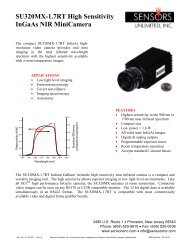
15. CAMERA CONTROL PROGRAM<br />
The Camera Control Program provides a GUI interface that allows you to send and receive<br />
control data and images from the camera. Below is an example dialog from the Windows version.<br />
23
16. APPLICATION ENVIRONMENTS<br />
In this section we will discuss several operating environments to give you an idea of what you<br />
need to operate the camera with a PC.<br />
Lens<br />
16.1 USB operation<br />
In this mode of operation you will need the following items:<br />
The Camera and a lens<br />
A power supply for the camera.<br />
A USB cable<br />
FastVision supplied USB software for your OS.<br />
<br />
All of the above can be supplied to you by FastVision. The software (item #4) provides<br />
two forms of access to the camera, via a library (DLL, or ActiveX control under Windows,<br />
linkable library under other operating systems), and via the supplied application called<br />
FastViewer.<br />
16.1.5 The hardware connections are:<br />
Camera<br />
USB<br />
Cable<br />
Power<br />
Supply<br />
Computer<br />
24
USB<br />
Device<br />
In<br />
Camera<br />
16.1.6 The software connections are:<br />
Operating<br />
System<br />
Provided<br />
USB<br />
Drivers<br />
FastVision<br />
Provided<br />
USB<br />
Device<br />
Driver<br />
25<br />
Library,<br />
DLL<br />
Or<br />
ActiveX<br />
Control<br />
Library,<br />
DLL<br />
Or<br />
ActiveX<br />
Control<br />
16.2 Using a FastVision supplied framegrabber<br />
Your<br />
Software<br />
FastVision<br />
FastViewer<br />
Software<br />
In this mode of operation you will need the following items, which can all be supplied by<br />
FastVision.<br />
The Camera and a lens<br />
A power supply for the camera<br />
One or more Camera Link cables<br />
FastVision supplied framegrabber<br />
FastVision supplied framegrabber software.
16.2.1 The hardware connections are:<br />
Lens<br />
Camera<br />
Serial<br />
And<br />
Channel<br />
Link<br />
Devices<br />
Camera<br />
Power<br />
Supply<br />
1 or 2<br />
Camera Link<br />
Cables<br />
16.2.2 The software connections are:<br />
Driver<br />
For<br />
FastVision<br />
Frame<br />
Grabber<br />
DLL, Library<br />
or<br />
ActiveX Control<br />
For<br />
FastVision<br />
Frame Grabber<br />
26<br />
Your Computer<br />
FastVision<br />
Provided<br />
Frame Grabber<br />
Your<br />
Software<br />
Camera<br />
Control<br />
Program<br />
FastVision Application<br />
Program Like FastViewer
16.3 Using a third-party framegrabber<br />
In this mode of operation you will need the following items:<br />
The Camera and a lens<br />
A power supply for the camera.<br />
One or more Camera Link cables.<br />
Your third-party framegrabber.<br />
AIA compliant software for your framegrabber.<br />
FastVision supplied camera control program.<br />
Lens<br />
16.3.1 The hardware connections are:<br />
Camera<br />
Power<br />
Supply<br />
1 or 2<br />
Camera Link<br />
Cables<br />
27<br />
Your Computer<br />
Third Party<br />
Provided<br />
Frame Grabber
16.3.2 The software connections are:<br />
Camera<br />
Serial<br />
And<br />
Channel<br />
Link<br />
Devices<br />
Driver<br />
for<br />
Your Frame<br />
Grabber<br />
28<br />
DLL or Library<br />
For Your<br />
Frame Grabber<br />
Camera Link<br />
Standard DLL<br />
FastVision<br />
Camera Control<br />
Application<br />
Your<br />
Software<br />
This will only work if your framegrabber supports the Camera Link standard serial<br />
interface protocol, and your framegrabber vendor has provided the needed DLL.<br />
Otherwise you will have to send commands to the camera in the way specified by<br />
your framegrabber vendor.<br />
17. TROUBLESHOOTING<br />
There are several things you can try before you call FastVision Technical Support for help.<br />
_____ Make sure the computer is plugged in. Make sure the power source is on.<br />
_____ Go back over the hardware installation to make sure that the system is properly<br />
installed.<br />
_____ Go back over the software installation to make sure you have installed all necessary<br />
software.<br />
_____ Run the Installation User Test to verify correct installation of both hardware and<br />
software.<br />
_____ Run the user-diagnostics test for your main board to make sure it’s working properly.<br />
_____ Insert the FastVision CD-ROM and check the various Release Notes to see if there is<br />
any information relevant to the problem you are experiencing.
The release notes are available in the directory: \usr\fastvision\alinfo<br />
18. FASTVISION TECHNICAL SUPPORT<br />
FastVision offers technical support to any licensed user during the normal business hours of 9<br />
a.m. to 5 p.m. EST. We offer assistance on all aspects of camera installation and operation.<br />
18.1 Contacting Technical Support<br />
To speak with a Technical Support Representative on the telephone, call the number<br />
below and ask for Technical Support:<br />
Telephone: 603-891-4317<br />
If you would rather FAX a written description of the problem, make sure you address the<br />
FAX to Technical Support and send it to:<br />
Fax: 603-891-1881<br />
You can email a description of the problem to support@fast-vision.com<br />
18.2 Returning Products for Repair or Replacements<br />
Our first concern is that you be pleased with your FastVision products.<br />
If, after trying everything you can do yourself, and after contacting FastVision Technical<br />
Support, you feel your hardware or software is not functioning properly, you can return<br />
the product to FastVision for service or replacement. Service or replacement may be<br />
covered by your warranty, depending upon your warranty. The first step is to call<br />
FastVision and request a “Return Materials Authorization” (RMA) number. This is the<br />
number assigned both to your returning product and to all records of your<br />
communications with Technical Support. When a FastVision technician receives your<br />
returned hardware or software he will match its RMA number to the on-file information<br />
you have given us, so he can solve the problem you’ve cited.<br />
When calling for an RMA number, please have the following information ready:<br />
_____ Serial numbers and descriptions of product(s) being shipped back<br />
_____ A listing including revision numbers for all software, libraries, applications,<br />
daughter cards, etc.<br />
_____ A clear and detailed description of the problem and when it occurs<br />
_____ Exact code that will cause the failure<br />
_____ A description of any environmental condition that can cause the problem<br />
29
All of this information will be logged into the RMA report so it’s there for the technician<br />
when your product arrives at FastVision. Put the camera inside its anti-static protective<br />
bags. Then pack the product(s) securely in the original shipping materials, if possible,<br />
and ship to:<br />
FastVision, LLC.<br />
71 Spit Brook Rd, Suite 210<br />
Nashua, NH 03060<br />
USA<br />
Clearly mark the outside of your package:<br />
Attention RMA #XXX<br />
Remember to include your return address and the name and number of the person who<br />
should be contacted if we have questions.<br />
18.3 Reporting Bugs<br />
We at FastVision are continually improving our products to ensure the success of your<br />
projects. In addition to ongoing improvements, every FastVision product is put through<br />
extensive and varied testing. Even so, occasionally situations can come up in the fields<br />
that were not encountered during our testing at FastVision.<br />
If you encounter a software or hardware problem or anomaly, please contact us<br />
immediately for assistance. If a fix is not available right away, often we can devise a<br />
work-around that allows you to move forward with your project while we continue to work<br />
on the problem you’ve encountered.<br />
It is important that we are able to reproduce your error in an isolated test case. You can<br />
help if you create a stand-alone code module that is isolated from your application and<br />
yet clearly demonstrates the anomaly or flaw.<br />
Describe the error that occurs with the particular code module and email the file to us at:<br />
support@fast-vision.com<br />
We will compile and run the module to track down the anomaly you’ve found.<br />
If you do not have Internet access, or if it is inconvenient for you to get to access, copy<br />
the code to a disk, describe the error, and mail the disk to Technical Support at the<br />
FastVision address below. If the code is small enough, you can also FAX the code<br />
module to us as indicated below.<br />
If you are faxing the code, write everything large and legibly and remember to include<br />
your description of the error.<br />
When you are describing a software problem, include revision numbers of all associated<br />
software.<br />
For documentation errors, photocopy the passages in question, mark on the page the<br />
number and title of the manual, and either FAX or mail the photocopy to FastVision.<br />
30
Remember to include the name and telephone number of the person we should contact if<br />
we have questions.<br />
FastVision, LLC.<br />
131 Daniel Webster Highway #529<br />
Nashua, NH 03060<br />
USA<br />
Telephone: 603-891-4317<br />
FAX: 603-891-1881<br />
Web site:<br />
http://www.fast-vision.com/<br />
Electronic Mail:<br />
sales@fast-vision.com<br />
support@fast-vision.com<br />
31