INDUCTION MACHINES I
INDUCTION MACHINES I
INDUCTION MACHINES I

You also want an ePaper? Increase the reach of your titles
YUMPU automatically turns print PDFs into web optimized ePapers that Google loves.
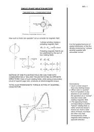
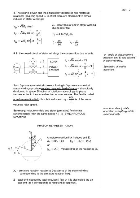
4. The rotor is driven and the sinusoidally distributed flux rotates at<br />
rotational (angular) speed ω. In effect there are electromotive forces<br />
induced in stator windings:<br />
e<br />
u<br />
e<br />
v<br />
e<br />
w<br />
=<br />
=<br />
=<br />
2E<br />
f<br />
sinωt<br />
⎛ 2 ⎞<br />
2E<br />
f<br />
sin⎜ωt<br />
− π ⎟<br />
⎝ 3 ⎠<br />
⎛ 4 ⎞<br />
2E<br />
f<br />
sin⎜ωt<br />
− π ⎟<br />
⎝ 3 ⎠<br />
Ef – rms value of emf in stator winding<br />
due to rotor flux<br />
E 4 . 44Nf<br />
k Φ<br />
f<br />
1<br />
f<br />
= 1<br />
w<br />
pn1<br />
= f<br />
60<br />
5. In the closed circuit of stator windings the currents flow due to emfs:<br />
i<br />
i<br />
i<br />
u<br />
v<br />
w<br />
=<br />
=<br />
=<br />
1<br />
f<br />
=<br />
ω<br />
2π<br />
2I<br />
sin<br />
( ωt<br />
− Ψ)<br />
⎛ 2 ⎞<br />
2I<br />
sin⎜ωt<br />
− π − Ψ ⎟<br />
⎝ 3 ⎠<br />
⎛ 4 ⎞<br />
2I<br />
sin⎜ωt<br />
− π − Ψ ⎟<br />
⎝ 3 ⎠<br />
Such 3-phase symmetrical currents flowing in 3-phase symmetrical<br />
stator windings produce rotating magnetic field of stator – sinusoidally<br />
distributed in space. Direction of rotation – accordingly to phase<br />
sequence, i.e. in the same direction as rotor rotates. The field is called<br />
60f1<br />
armature reaction field. Its rotational speed n1<br />
= is of the same<br />
p<br />
value as rotor speed.<br />
Summary: rotor, rotor field and stator (armature) field rotate<br />
synchronously (with the same speed n1) ⇒ SYNCHRONOUS<br />
MACHINE!<br />
PHASOR REPRESENTATION<br />
Armature reaction flux induces emf Ea<br />
E = cΦ<br />
= c I E = − c I = −jX<br />
I<br />
U<br />
a<br />
or<br />
a<br />
a<br />
a<br />
1<br />
a<br />
j 1<br />
= jX<br />
I − voltage drop at the reactance X<br />
Xa – armature reaction reactance (reactance of the stator winding<br />
corresponding to the armature reaction flux).<br />
E – total emf induced by total (resultant) flux Φ. It is also called the airgap<br />
emf (as it corresponds to resultant air-gap flux).<br />
a<br />
a<br />
SM1- 2<br />
Ψ - angle of displacement<br />
between emf Ef and current I<br />
in stator winding.<br />
Symmetry of load is<br />
assumed.<br />
In normal steady-state<br />
operation everything rotate<br />
synchronously.