INDUCTION MACHINES I
INDUCTION MACHINES I
INDUCTION MACHINES I

Create successful ePaper yourself
Turn your PDF publications into a flip-book with our unique Google optimized e-Paper software.
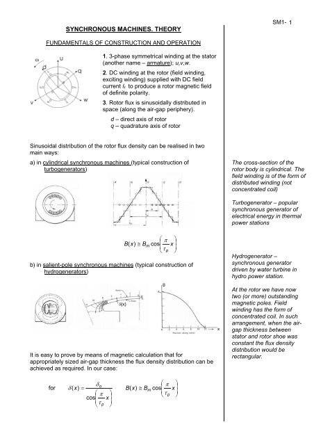
SYNCHRONOUS <strong>MACHINES</strong>. THEORY<br />
FUNDAMENTALS OF CONSTRUCTION AND OPERATION<br />
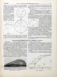
1. 3-phase symmetrical winding at the stator<br />
(another name – armature); u,v,w.<br />
2. DC winding at the rotor (field winding,<br />
exciting winding) supplied with DC field<br />
current If to produce a rotor magnetic field<br />
of definite polarity.<br />
3. Rotor flux is sinusoidally distributed in<br />
space (along the air-gap periphery).<br />
d – direct axis of rotor<br />
q – quadrature axis of rotor<br />
Sinusoidal distribution of the rotor flux density can be realised in two<br />
main ways:<br />
a) in cylindrical synchronous machines (typical construction of<br />
turbogenerators)<br />
⎛ ⎞<br />
⎜<br />
π<br />
B(<br />
x)<br />
≅ B x ⎟<br />
m cos<br />
⎜ ⎟<br />
⎝τ<br />
p ⎠<br />
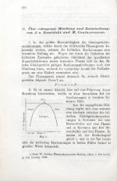
b) in salient-pole synchronous machines (typical construction of<br />
hydrogenerators)<br />
It is easy to prove by means of magnetic calculation that for<br />
appropriately sized air-gap thickness the flux density distribution can be<br />
achieved as required. In our case:<br />
for<br />
δ<br />
⎛ ⎞<br />
o<br />
⎜<br />
π<br />
δ ( x)<br />
= B(<br />
x)<br />
≅ B x ⎟<br />
m cos<br />
⎛ ⎞<br />
⎜ ⎟<br />
⎜ π<br />
x ⎟<br />
⎝τ<br />
p<br />
cos<br />
⎠<br />
⎜ ⎟<br />
⎝τ<br />
p ⎠<br />
SM1- 1<br />
The cross-section of the<br />
rotor body is cylindrical. The<br />
field winding is of the form of<br />
distributed winding (not<br />
concentrated coil)<br />
Turbogenerator – popular<br />
synchronous generator of<br />
electrical energy in thermal<br />
power stations<br />
Hydrogenerator –<br />
synchronous generator<br />
driven by water turbine in<br />
hydro power station.<br />
At the rotor we have now<br />
two (or more) outstanding<br />
magnetic poles. Field<br />
winding has the form of<br />
concentrated coil. In such<br />
arrangement, when the airgap<br />
thickness between<br />
stator and rotor shoe was<br />
constant the flux density<br />
distribution would be<br />
rectangular.
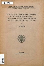
4. The rotor is driven and the sinusoidally distributed flux rotates at<br />
rotational (angular) speed ω. In effect there are electromotive forces<br />
induced in stator windings:<br />
e<br />
u<br />
e<br />
v<br />
e<br />
w<br />
=<br />
=<br />
=<br />
2E<br />
f<br />
sinωt<br />
⎛ 2 ⎞<br />
2E<br />
f<br />
sin⎜ωt<br />
− π ⎟<br />
⎝ 3 ⎠<br />
⎛ 4 ⎞<br />
2E<br />
f<br />
sin⎜ωt<br />
− π ⎟<br />
⎝ 3 ⎠<br />
Ef – rms value of emf in stator winding<br />
due to rotor flux<br />
E 4 . 44Nf<br />
k Φ<br />
f<br />
1<br />
f<br />
= 1<br />
w<br />
pn1<br />
= f<br />
60<br />
5. In the closed circuit of stator windings the currents flow due to emfs:<br />
i<br />
i<br />
i<br />
u<br />
v<br />
w<br />
=<br />
=<br />
=<br />
1<br />
f<br />
=<br />
ω<br />
2π<br />
2I<br />
sin<br />
( ωt<br />
− Ψ)<br />
⎛ 2 ⎞<br />
2I<br />
sin⎜ωt<br />
− π − Ψ ⎟<br />
⎝ 3 ⎠<br />
⎛ 4 ⎞<br />
2I<br />
sin⎜ωt<br />
− π − Ψ ⎟<br />
⎝ 3 ⎠<br />
Such 3-phase symmetrical currents flowing in 3-phase symmetrical<br />
stator windings produce rotating magnetic field of stator – sinusoidally<br />
distributed in space. Direction of rotation – accordingly to phase<br />
sequence, i.e. in the same direction as rotor rotates. The field is called<br />
60f1<br />
armature reaction field. Its rotational speed n1<br />
= is of the same<br />
p<br />
value as rotor speed.<br />
Summary: rotor, rotor field and stator (armature) field rotate<br />
synchronously (with the same speed n1) ⇒ SYNCHRONOUS<br />
MACHINE!<br />
PHASOR REPRESENTATION<br />
Armature reaction flux induces emf Ea<br />
E = cΦ<br />
= c I E = − c I = −jX<br />
I<br />
U<br />
a<br />
or<br />
a<br />
a<br />
a<br />
1<br />
a<br />
j 1<br />
= jX<br />
I − voltage drop at the reactance X<br />
Xa – armature reaction reactance (reactance of the stator winding<br />
corresponding to the armature reaction flux).<br />
E – total emf induced by total (resultant) flux Φ. It is also called the airgap<br />
emf (as it corresponds to resultant air-gap flux).<br />
a<br />
a<br />
SM1- 2<br />
Ψ - angle of displacement<br />
between emf Ef and current I<br />
in stator winding.<br />
Symmetry of load is<br />
assumed.<br />
In normal steady-state<br />
operation everything rotate<br />
synchronously.
SPECIAL CASES OF ARMATURE REACTION<br />
a) direct-axis armature reaction<br />
For such conditions of Φa the stator winding is characterised by:<br />
Xad – direct-axis armature reaction reactance.<br />
Ψ=π/2 corresponds to pure inductive load current (with respect to Ef).<br />
Consider also Ψ=-π/2 (capacitive character of load).<br />
b) quadrature-axis armature reaction<br />
Ψ=0 – active load current.<br />
For such conditions of Φa the stator winding is characterised by:<br />
Xaq – quadrature-axis armature reaction reactance.<br />
For cylindrical machines: Xad ≈ Xaq<br />
For salient-pole machines Xad > Xaq<br />
When we take into consideration also the leakage flux of stator winding,<br />
each phase will be characterised by the sum of reactances:<br />
Xl + Xad = Xd – direct-axis synchronous reactance,<br />
Xl + Xaq = Xq – quadrature-axis synchronous reactance.<br />
For cylindrical machines: Xd ≈ Xq<br />
For salient-pole machines Xd > Xq<br />
SM1- 3<br />
Check carefully and<br />
compare the magnetic<br />
conditions for fluxes Φa in<br />
both cases: d and q<br />
positions in space and time.<br />
Xl – leakage reactance of<br />
stator winding.
c) Any other position of I and Φa<br />
- for cylindrical machine – magnetic path for Φa remains the same<br />
and Xd (= Xq) can be assumed as parameter representing the<br />
stator winding;<br />
- for salient-pole machine – magnetic path for Φa is variable and<br />
depends on Ψ. For each value of Ψ an appropriate value of Xa<br />
should be determined or superposition method of d-armature<br />
reaction and q-armature reaction should be applied (Blondel’s<br />
diagram).<br />
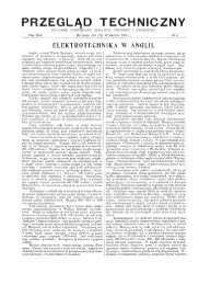
EQUIVALENT CIRCUIT OF CYLINDRICAL MACHINE (GENERATOR)<br />
and phasor diagram<br />
or simplified phasor diagram (R1 ≈ 0);<br />
( X + X ) I = X I<br />
Us ad l d<br />
ϑL – load angle<br />
ϕ - phase angle<br />
INDIVIDUAL LOAD<br />
OR<br />
POWER SYSTEM<br />
= - voltage drop at synchronous reactance<br />
Voltage balance equations:<br />
E<br />
E<br />
f<br />
f<br />
=<br />
U + jX I + jX<br />
I + R1I<br />
= U + jX<br />
ad<br />
d<br />
I<br />
l<br />
SM1- 4