Establishing Controlled Source MT at GFZ
Establishing Controlled Source MT at GFZ
Establishing Controlled Source MT at GFZ

Create successful ePaper yourself
Turn your PDF publications into a flip-book with our unique Google optimized e-Paper software.
<strong>Establishing</strong> <strong>Controlled</strong> <strong>Source</strong> <strong>MT</strong> <strong>at</strong> <strong>GFZ</strong><br />
M. Becken 1,2 , R. Streich 1,2 , O. Ritter 2<br />
1 Potsdam University, Department of Geosciences, Karl-Liebknecht-Strasse 24, 14476 Potsdam, Germany<br />
2 Helmholtz Centre Potsdam <strong>GFZ</strong> German Research Centre for Geosciences, Telegrafenberg, 14473 Potsdam, Germany<br />
Summary<br />
The multidisciplinary GeoEn project (the Brandenburg pilot project in the BMBF program<br />
„Spitzenforschung und Innov<strong>at</strong>ion in den Neuen Ländern“) integr<strong>at</strong>es research in the fields of<br />
geothermal energy, carbon dioxide capture, transport and storage (CCTS) as well as the explor<strong>at</strong>ion of<br />
unconventional gas reserves (shale gas). The electrical conductivity is one key parameter to characterize<br />
reservoirs and to monitor changes due to circul<strong>at</strong>ion or injection of fluids <strong>at</strong> reservoir depth. Bulk<br />
electrical conductivity is highly sensitive to fluids within interconnected pores, and therefore EM<br />
techniques are powerful tools for exploring and monitoring geothermal reservoirs, CO2 storage sites and<br />
shale gas reservoirs. In the framework of the GeoEn project, we establish <strong>Controlled</strong> <strong>Source</strong> <strong>MT</strong> (CS<strong>MT</strong>)<br />
<strong>at</strong> <strong>GFZ</strong> Potsdam. We aim <strong>at</strong> combining active and passive <strong>MT</strong> to image the electrical conductivity<br />
structure within the Earth, ultim<strong>at</strong>ely in 3D.<br />
For CS<strong>MT</strong>, we intend to use grounded electrodes to inject a frequency-dependent current into the Earth<br />
and measure the induced electric and magnetic fields <strong>at</strong> near-field to far-field distances. We will use<br />
novel transmitter systems from Metronix (Braunschweig) which are presently under development.<br />
Standard <strong>MT</strong> receivers will be utilized to measure the induced electric and magnetic fields. In the scope<br />
of the project, we will (i) assemble the transmitter system and the source dipole, (ii) optimize and design<br />
CS<strong>MT</strong> field procedures for geothermal explor<strong>at</strong>ion, carbon dioxide reservoir characteriz<strong>at</strong>ion and shale<br />
gas explor<strong>at</strong>ion (Streich et al., 2010a), (iii) develop and implement time-series processing, (iv) develop<br />
and implement 1D modeling (Streich and Becken, 2009) and inversion software and 3D modeling codes<br />
(Streich, 2009; Streich et al., 2010b).<br />
In this contribution, we describe a test of long steel electrodes as the current electrodes of the source<br />
dipole, and we examine the resolution power of CS<strong>MT</strong> using 1D inversion of synthetic d<strong>at</strong>a.<br />
Current electrodes of CS<strong>MT</strong> source dipole<br />
Low grounding resistances of the current electrodes are crucial for injecting strong currents into the<br />
subsurface. The Metronix 22 kVA transmitter gener<strong>at</strong>es currents of max. 40 A (560 V), which can,<br />
however, only be achieved if the total resistance of the dipole (1-km long cable and grounding<br />
electrodes) is less than 14 . We use a thick cable th<strong>at</strong> has a resistance of 2 /km. Accordingly, to<br />
achieve maximum currents, the electrode grounding resistances should be less than 12 . At high<br />
frequencies, the maximum current will be further limited by the inductance of the cable.<br />
The grounding resistance depends primarily on the surface of the electrode th<strong>at</strong> is in contact with the<br />
ground, and the surrounding resistivity within the Earth. For a homogenous earth, the grounding<br />
resistance R of a steel rod is<br />
R<br />
4L<br />
ln<br />
2 L<br />
a<br />
1<br />
, (1)<br />
23. Schmucker-Weidelt-Kolloquium für Elektromagnetische Tiefenforschung,<br />
Heimvolkshochschule am Seddiner See, 28 September - 2 Oktober 2009<br />
71
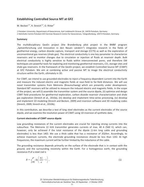
Figure 1: Electrode test. We measured the ground resistance of a steel electrode (diameter 32 mm) vs. depth of<br />
the rod <strong>at</strong> two different loc<strong>at</strong>ions, which may represent typical conditions in northern Germany. Ground resistance<br />
measurements were taken against two reference electrodes <strong>at</strong> ~30 m distance to the left and right. DC Wenner<br />
spreads were measured <strong>at</strong> the same loc<strong>at</strong>ions (left panels). The panels to the right show the measured resistances<br />
(red and blue lines), compared to theoretical predictions (dashed black lines) based on the resistivity-depth<br />
profiles <strong>at</strong> the electrode loc<strong>at</strong>ions shown in the rightmost plots. The sudden drop in resistance <strong>at</strong>
gre<strong>at</strong>er depths, we penetr<strong>at</strong>e conductive glacial till <strong>at</strong> test loc<strong>at</strong>ion 1 (upper panel in Figure 1) and a<br />
groundw<strong>at</strong>er layer <strong>at</strong> test loc<strong>at</strong>ion 2 (lower panel). The measured grounding resistance values are<br />
roughly consistent with predictions (dashed lines) based on the geometry and the subsurface resistivity<br />
distribution. For resistance predictions, we approxim<strong>at</strong>ed the resistance R from a parallel circuit of steel<br />
rod segments of length L embedded into a medium with piecewise constant resistivity i .<br />
Approxim<strong>at</strong>e i values were extracted from the 2D DC resistivity-depth sections. Let the individual rod<br />
pieces have resistance<br />
R<br />
i<br />
i 4 L<br />
ln<br />
2 L a<br />
then the resistance of the entire rod to a depth L is given by<br />
1<br />
R<br />
1<br />
i i R<br />
1<br />
, (3)<br />
. (4)<br />
Equ<strong>at</strong>ions 3 and 4 were used to estim<strong>at</strong>e grounding resistances from the 2D resistivity models (Figure 1).<br />
This test shows th<strong>at</strong> long steel rods may be suitable electrodes for CS<strong>MT</strong> source dipoles. At one test<br />
loc<strong>at</strong>ion with favorable geology (glacial till), we achieved a ground resistance of ~10 with electrodes<br />
penetr<strong>at</strong>ing 7.5 m deep; the second test loc<strong>at</strong>ion, a sandy soil with a freshw<strong>at</strong>er layer <strong>at</strong> ~3 m depth,<br />
may require deeper electrodes. Our predictions suggest th<strong>at</strong> the ground resistance of the steel rod may<br />
drop <strong>at</strong> this loc<strong>at</strong>ion to values of ~10 <strong>at</strong> ~15 m depth. The simple model used to predict grounding<br />
resistance has proven to be useful for practical purposes. Before installing electrodes, it may be<br />
advisable to investig<strong>at</strong>e potential loc<strong>at</strong>ions with DC resistivity soundings in order to predict expectable<br />
resistances and required electrode lengths.<br />
1D CS<strong>MT</strong> Inversion<br />
Vertical currents, galvanically injected into the subsurface with a grounded dipole source, exhibit<br />
sensitivity to buried resistors <strong>at</strong> depth. This makes the CS<strong>MT</strong> technique suitable for imaging resistive<br />
layers, whereas both passive <strong>MT</strong> and CS<strong>MT</strong> are sensitive to conductive layers. The effect of anomalously<br />
resistive subsurface structures on surface CS<strong>MT</strong> d<strong>at</strong>a is typically smaller in land applic<strong>at</strong>ions than in<br />
deep-w<strong>at</strong>er marine applic<strong>at</strong>ions. Land applic<strong>at</strong>ions of frequency-domain CS<strong>MT</strong> suffer from energy<br />
travelling through the air even more than marine applic<strong>at</strong>ions, which obscures the response from<br />
deeper targets. Nevertheless, forward modeling studies suggest th<strong>at</strong> in many cases, the e.m. response<br />
of thin resistive layers is above noise level (see Streich and Becken, this issue).<br />
A practical question is to wh<strong>at</strong> extent the resistivity models giving rise to these anomalies can be<br />
recovered from measured d<strong>at</strong>a. We ran 1D Occam-type inversions to investig<strong>at</strong>e the resolution power of<br />
CS<strong>MT</strong> d<strong>at</strong>a. To infer the resistivity structure from 1D inversion, we can exploit the sp<strong>at</strong>ial decay of CS<strong>MT</strong><br />
fields with increasing distance to the source, and the frequency dependency of the fields. In land-based<br />
applic<strong>at</strong>ions, we will typically have only few source loc<strong>at</strong>ions combined with a rel<strong>at</strong>ively large number of<br />
receivers (say, 100), and potentially long transmitting times th<strong>at</strong> allow us to cover a broad frequency<br />
range. In contrast, marine applic<strong>at</strong>ions use a source towed continuously over a number of receivers,<br />
effectively yielding many source point loc<strong>at</strong>ions, but only short transmitting times and thus a narrow<br />
frequency band for a given source loc<strong>at</strong>ion. Hence, land applic<strong>at</strong>ions will primarily utilize the frequency<br />
23. Schmucker-Weidelt-Kolloquium für Elektromagnetische Tiefenforschung,<br />
Heimvolkshochschule am Seddiner See, 28 September - 2 Oktober 2009<br />
73
Figure 2: 1D Occam inversion of synthetic CS<strong>MT</strong> d<strong>at</strong>a. The d<strong>at</strong>a are the real and imaginary parts of the inline<br />
electric field, contamin<strong>at</strong>ed with white noise with 1% of the signal amplitude. In addition, white noise with a<br />
standard devi<strong>at</strong>ion of 10 -9 V/m was added. a) Inversion of the sp<strong>at</strong>ial decay of the field for a single frequency (1<br />
Hz), using an unconstrained Occam inversion and using an Occam variant where the devi<strong>at</strong>ion from an a priori<br />
model is penalized outside of the depth of interest. b) Inversion of the frequency spectrum recorded <strong>at</strong> 5 km<br />
distance from the transmitter.<br />
Figure 3: Comparison of single and joint 1D inversion models for passive <strong>MT</strong> and CS<strong>MT</strong> d<strong>at</strong>a. In (a), the left panel<br />
shows passive <strong>MT</strong> d<strong>at</strong>a (apparent resistivity and phase) for the true model and <strong>MT</strong> inversion result displayed in the<br />
right panel. In (b), CS<strong>MT</strong> d<strong>at</strong>a (real and imaginary part of the inline electric field) are displayed for the true<br />
resistivity model and CS<strong>MT</strong> inversion result. (c) shows the resistivity model resulting from joint <strong>MT</strong> and CS<strong>MT</strong><br />
inversion. In this example, the <strong>MT</strong> d<strong>at</strong>a add inform<strong>at</strong>ion only <strong>at</strong> gre<strong>at</strong>er depths, where the sensitivity of CS<strong>MT</strong><br />
sounding is low. In practice, we anticip<strong>at</strong>e th<strong>at</strong> <strong>MT</strong> d<strong>at</strong>a will help construct a (2D/3D) regional background model,<br />
and CS<strong>MT</strong> d<strong>at</strong>a will help refine the model <strong>at</strong> reservoir scale (1D/3D).<br />
dependency of the fields, whereas marine applic<strong>at</strong>ions will primarily exploit sp<strong>at</strong>ial vari<strong>at</strong>ions of the<br />
fields.<br />
We have implemented a 1D CS<strong>MT</strong> inversion based on Weidelt’s formul<strong>at</strong>ion of the forward problem<br />
(Weidelt, 2007), and analytically derived expressions for the Jacobian m<strong>at</strong>rix required in the inversion.<br />
Finite source dipoles (Streich and Becken, this issue) have been incorpor<strong>at</strong>ed into the inversion;<br />
however, in the present form of the inversion scheme, the source and receivers are placed <strong>at</strong> the<br />
surface. Here, we only consider horizontal electric point dipole sources. The inversion is similar to<br />
23. Schmucker-Weidelt-Kolloquium für Elektromagnetische Tiefenforschung,<br />
Heimvolkshochschule am Seddiner See, 28 September - 2 Oktober 2009<br />
74
Occam inversion (Constable et al., 1987); however, Occam’s second phase (i.e., the determin<strong>at</strong>ion of the<br />
regulariz<strong>at</strong>ion parameter th<strong>at</strong> yields optimal trade-off between d<strong>at</strong>a residuals and model norm) has not<br />
been implemented. Instead, we fix the regulariz<strong>at</strong>ion parameter for one entire inversion run.<br />
Using this inversion scheme, we found th<strong>at</strong> both the inversion of multi-offset d<strong>at</strong>a <strong>at</strong> a single frequency<br />
and multi-frequency d<strong>at</strong>a <strong>at</strong> a single receiver loc<strong>at</strong>ion have the power to yield comparable inversion<br />
models, if the frequency range and the distance to the transmitter are appropri<strong>at</strong>e for imaging the<br />
target depth (Figure 2). The left panels in Figure 2a and b depict the inline electric field as a function of<br />
distance from the transmitter for the frequency f = 1 Hz and as a function of frequency <strong>at</strong> 5 km distance,<br />
respectively, for a model containing a resistive layer embedded into a homogeneous half-space.<br />
Random noise of 1% of the field amplitudes and a noise floor of 10 -9 V/m were added to the d<strong>at</strong>a prior to<br />
inversion. The central panel in Figure 2a shows the inversion model obtained from smooth inversion<br />
using a standard Laplacian penalty on the logarithmic model resistivities (red line). A similar result (not<br />
shown) was obtained from inversion of the multi-frequency electric field d<strong>at</strong>a shown in Figure 2b. In<br />
both cases, the recovered 1D model contains a resistive zone th<strong>at</strong> is smeared over a wide depth range,<br />
because regulariz<strong>at</strong>ion penalizes thin model layers.<br />
For monitoring applic<strong>at</strong>ions (e.g., CO2 injection), the depth of interest is known. A focused inversion th<strong>at</strong><br />
searches for devi<strong>at</strong>ions from an a priori model primarily <strong>at</strong> reservoir depth may help improve the model.<br />
We have therefore incorpor<strong>at</strong>ed a term into the Occam inversion th<strong>at</strong> allows us to weight the penalty<br />
depending on the difference of every inversion model parameter to an a priori model (Key, 2009). The<br />
right panels in Figure 2a and b show the result of this variant of regularized inversion. The hashed areas<br />
correspond to depth levels where the inversion model is constrained to devi<strong>at</strong>e minimally from the a<br />
priori model (which is the true model in this case), whereas the rest of the model was permitted to vary<br />
freely (in the sense of a Laplacian regulariz<strong>at</strong>ion). This approach clearly helps focusing the resistive<br />
anomaly <strong>at</strong> the true depth and may thus be adequ<strong>at</strong>e for a focused model search.<br />
The penetr<strong>at</strong>ion depth of CS<strong>MT</strong> d<strong>at</strong>a is limited by the lowest frequencies used and the gre<strong>at</strong>est offsets<br />
providing reasonable signal quality. Combing CS<strong>MT</strong> with passive <strong>MT</strong> may prove helpful to expand the<br />
model scale. Furthermore, both techniques exhibit different sensitivities to resistive and conductive<br />
structures (and to devi<strong>at</strong>ions from 1D media) and thus provide complementary inform<strong>at</strong>ion. We have<br />
therefore implemented a joint 1D inversion for both d<strong>at</strong>a types. In Figure 3, we compare the 1D<br />
inversion models for a multi-layered structure obtained from <strong>MT</strong> d<strong>at</strong>a and CS<strong>MT</strong> d<strong>at</strong>a alone and from<br />
joint CS<strong>MT</strong> and <strong>MT</strong> inversion. Here, the CS<strong>MT</strong> d<strong>at</strong>a are the frequency-dependent inline electric field<br />
d<strong>at</strong>a, measured <strong>at</strong> 5 km offset from the transmitter. The individual inversion models show th<strong>at</strong> (i) both<br />
techniques resolve shallow conductive layers, (ii) the CS<strong>MT</strong> d<strong>at</strong>a resolve a resistive layer <strong>at</strong> 1 km depth,<br />
and (iii) the <strong>MT</strong> d<strong>at</strong>a resolve the conductivity of the basal layer th<strong>at</strong> is too deep to be sensed with CS<strong>MT</strong>.<br />
All of these model fe<strong>at</strong>ures are revealed by joint inversion, suggesting increased resolution capabilities<br />
from combined applic<strong>at</strong>ions of both techniques.<br />
Acknowledgements<br />
This work is funded by the German Federal Ministry of Educ<strong>at</strong>ion and Research (BMBF) within the<br />
framework of the GeoEn project. S. Costabel, TU Berlin, made the DC measurements and provided the<br />
2D inversion models.<br />
23. Schmucker-Weidelt-Kolloquium für Elektromagnetische Tiefenforschung,<br />
Heimvolkshochschule am Seddiner See, 28 September - 2 Oktober 2009<br />
75
References:<br />
Constable, S. C., Parker, R. L. and Constable, C. G., 1987, Occam's inversion: A practical algorithm for<br />
gener<strong>at</strong>ing smooth models from electromagnetic sounding d<strong>at</strong>a, Geophysics 75(3), 289-300.<br />
Key, K., 2009, 1D inversion of multicomponent, multifrequency marine CSEM d<strong>at</strong>a: Methodology and<br />
synthetic studies for resolving thin resistive layers, Geophysics 74(2), F9-F20.<br />
Streich, R., 2009, 3D finite-difference frequency-domain modeling of controlled-source electromagnetic<br />
d<strong>at</strong>a: direct solution and optimiz<strong>at</strong>ion for high accuracy, Geophysics 74(5), F95-F105.<br />
Streich, R., Becken, M. and Ritter, O., 2010a, Imaging of CO2 storage sites, geothermal reservoirs, and<br />
gas shales using controlled-source magnetotellurics: modeling studies, Chemie der Erde, submitted.<br />
Streich, R. and Becken, M., 2010, EM fields gener<strong>at</strong>ed by finite-length wire sources in 1D media:<br />
comparison with point dipole solutions, Protokoll zum Kolloquium “Elektromagnetische Tiefenforschung”,<br />
Seddiner See, 28.09.-02.10.2009.<br />
Streich, R., Schwarzbach, C., Becken, M. and Spitzer, K., 2010b, <strong>Controlled</strong>-source electromagnetic<br />
modelling studies: utility of auxiliary potentials for low-frequency stabiliz<strong>at</strong>ion, EAGE 70 th Conference<br />
and Exhibition, Barcelona, Spain, submitted.<br />
Weidelt, P., 2007, Guided waves in marine CSEM: Geophysical Journal Intern<strong>at</strong>ional, 171, 153–176.<br />
23. Schmucker-Weidelt-Kolloquium für Elektromagnetische Tiefenforschung,<br />
Heimvolkshochschule am Seddiner See, 28 September - 2 Oktober 2009<br />
76