Aurora V2 User Guide
Aurora V2 User Guide
Aurora V2 User Guide

Create successful ePaper yourself
Turn your PDF publications into a flip-book with our unique Google optimized e-Paper software.
<strong>Aurora</strong> <strong>V2</strong> <strong>User</strong> <strong>Guide</strong><br />
Revision 3<br />
July 2012<br />
IMPORTANT<br />
Please read this entire document before<br />
operating the <strong>Aurora</strong> System
p Printed in Canada.<br />
Revision Status<br />
Revision Number Date Description<br />
1 March 2011 Initial release<br />
2 October 2011 Added Tabletop Field Generator information<br />
3 July 2012 Updated SCU symbology. Added additional<br />
warnings to comply with IEC 60601-1 3rd edition<br />
Part Number: IL-1070195
Published by:<br />
Northern Digital Inc.<br />
103 Randall Dr.<br />
Waterloo, Ontario, Canada N2V 1C5<br />
Telephone: + (519) 884-5142<br />
Toll Free: + (877) 634-6340<br />
Global: + (800) 634 634 00<br />
Facsimile: + (519) 884-5184<br />
Website: www.ndigital.com<br />
Copyright 2011, 2012, Northern Digital Inc.<br />
All rights reserved. No part of this document may be reproduced, transcribed, transmitted, distributed, modified,<br />
merged or translated into any language in any form by any means - graphic, electronic, or mechanical,<br />
including but not limited to photocopying, recording, taping or information storage and retrieval systems - without<br />
the prior written consent of Northern Digital Inc. Certain copying of the software included herein is unlawful.<br />
Refer to your software license agreement for information respecting permitted copying.<br />
DISCLAIMER OF WARRANTIES AND LIMITATION OF LIABILITIES<br />
Northern Digital Inc. has taken due care in preparing this document and the programs and data on the electronic<br />
media accompanying this document including research, development, and testing.<br />
This document describes the state of Northern Digital Inc.’s knowledge respecting the subject matter herein at<br />
the time of its publication, and may not reflect its state of knowledge at all times in the future. Northern Digital<br />
Inc. has carefully reviewed this document for technical accuracy. If errors are suspected, the user should consult<br />
with Northern Digital Inc. prior to proceeding. Northern Digital Inc. makes no expressed or implied warranty<br />
of any kind with regard to this document or the programs and data on the electronic media accompanying this<br />
document.<br />
Northern Digital Inc. makes no representation, condition or warranty to the user or any other party with respect<br />
to the adequacy of this document or accompanying media for any particular purpose or with respect to its adequacy<br />
to produce a particular result. The user’s right to recover damages caused by fault or negligence on the<br />
part of Northern Digital Inc. shall be limited to the amount paid by the user to Northern Digital Inc. for the provision<br />
of this document. In no event shall Northern Digital Inc. be liable for special, collateral, incidental, direct,<br />
indirect or consequential damages, losses, costs, charges, claims, demands, or claim for lost profits, data, fees<br />
or expenses of any nature or kind.<br />
Product names listed are trademarks of their respective manufacturers. Company names listed are trademarks<br />
or trade names of their respective companies.<br />
<strong>Aurora</strong> <strong>V2</strong> <strong>User</strong> <strong>Guide</strong> - Revision 3
<strong>Aurora</strong> <strong>V2</strong> <strong>User</strong> <strong>Guide</strong> - Revision 3
Table of Contents<br />
Table of Contents<br />
Read Me First . . . . . . . . . . . . . . . . . . . . . . . . . . . . . . . . . . . . . . . . . . . . . . . . . . . . . . . . . . . . . . . . . . . . . . viii<br />
Warnings . . . . . . . . . . . . . . . . . . . . . . . . . . . . . . . . . . . . . . . . . . . . . . . . . . . . . . . . . . . . .viii<br />
Cautions . . . . . . . . . . . . . . . . . . . . . . . . . . . . . . . . . . . . . . . . . . . . . . . . . . . . . . . . . . . . . . . x<br />
Disclaimers . . . . . . . . . . . . . . . . . . . . . . . . . . . . . . . . . . . . . . . . . . . . . . . . . . . . . . . . . . . . x<br />
Contact . . . . . . . . . . . . . . . . . . . . . . . . . . . . . . . . . . . . . . . . . . . . . . . . . . . . . . . . . . . . . . . .xi<br />
Updates . . . . . . . . . . . . . . . . . . . . . . . . . . . . . . . . . . . . . . . . . . . . . . . . . . . . . . . . . . . . . . xii<br />
1 <strong>Aurora</strong> System Overview . . . . . . . . . . . . . . . . . . . . . . . . . . . . . . . . . . . . . . . . . . . . . . . . . . . . . . . . . . . . . 1<br />
1.1 Introduction . . . . . . . . . . . . . . . . . . . . . . . . . . . . . . . . . . . . . . . . . . . . . . . . . . . . . . . . . 1<br />
1.2 Principles of Operation . . . . . . . . . . . . . . . . . . . . . . . . . . . . . . . . . . . . . . . . . . . . . . . . 2<br />
1.3 Planar Field Generator. . . . . . . . . . . . . . . . . . . . . . . . . . . . . . . . . . . . . . . . . . . . . . . . . 4<br />
1.4 Tabletop Field Generator. . . . . . . . . . . . . . . . . . . . . . . . . . . . . . . . . . . . . . . . . . . . . . . 5<br />
1.5 System Control Unit . . . . . . . . . . . . . . . . . . . . . . . . . . . . . . . . . . . . . . . . . . . . . . . . . . 6<br />
1.6 Sensor Interface Unit. . . . . . . . . . . . . . . . . . . . . . . . . . . . . . . . . . . . . . . . . . . . . . . . . 10<br />
1.7 Accessories . . . . . . . . . . . . . . . . . . . . . . . . . . . . . . . . . . . . . . . . . . . . . . . . . . . . . . . . 10<br />
1.8 Service Life/Disposal . . . . . . . . . . . . . . . . . . . . . . . . . . . . . . . . . . . . . . . . . . . . . . . . 12<br />
2 Setting up the <strong>Aurora</strong> System. . . . . . . . . . . . . . . . . . . . . . . . . . . . . . . . . . . . . . . . . . . . . . . . . . . . . . . . . 13<br />
2.1 Unpacking the <strong>Aurora</strong> System. . . . . . . . . . . . . . . . . . . . . . . . . . . . . . . . . . . . . . . . . . 13<br />
2.2 General Warnings . . . . . . . . . . . . . . . . . . . . . . . . . . . . . . . . . . . . . . . . . . . . . . . . . . . 13<br />
2.3 Mounting the Components . . . . . . . . . . . . . . . . . . . . . . . . . . . . . . . . . . . . . . . . . . . . 15<br />
2.4 Cable Management . . . . . . . . . . . . . . . . . . . . . . . . . . . . . . . . . . . . . . . . . . . . . . . . . . 18<br />
2.5 Connecting the Components . . . . . . . . . . . . . . . . . . . . . . . . . . . . . . . . . . . . . . . . . . . 19<br />
3 Using the <strong>Aurora</strong> System . . . . . . . . . . . . . . . . . . . . . . . . . . . . . . . . . . . . . . . . . . . . . . . . . . . . . . . . . . . . 21<br />
3.1 Introduction . . . . . . . . . . . . . . . . . . . . . . . . . . . . . . . . . . . . . . . . . . . . . . . . . . . . . . . . 21<br />
3.2 Powering on the <strong>Aurora</strong> System . . . . . . . . . . . . . . . . . . . . . . . . . . . . . . . . . . . . . . . . 21<br />
3.3 Installing the Software (Windows) . . . . . . . . . . . . . . . . . . . . . . . . . . . . . . . . . . . . . . 21<br />
3.4 Installing the Software (Linux) . . . . . . . . . . . . . . . . . . . . . . . . . . . . . . . . . . . . . . . . . 24<br />
3.5 Installing the Software (Mac OS X) . . . . . . . . . . . . . . . . . . . . . . . . . . . . . . . . . . . . . 26<br />
3.6 <strong>Aurora</strong> System Tools. . . . . . . . . . . . . . . . . . . . . . . . . . . . . . . . . . . . . . . . . . . . . . . . . 31<br />
<strong>Aurora</strong> <strong>V2</strong> <strong>User</strong> <strong>Guide</strong> - Revision 3 i
Table of Contents<br />
4 Tutorial: Learning to Use the <strong>Aurora</strong> System (NDI ToolBox) . . . . . . . . . . . . . . . . . . . . . . . . . . . . . . . 34<br />
4.1 Getting Started: Tracking Tools. . . . . . . . . . . . . . . . . . . . . . . . . . . . . . . . . . . . . . . . . 34<br />
4.2 Information and Error Flags. . . . . . . . . . . . . . . . . . . . . . . . . . . . . . . . . . . . . . . . . . . . 35<br />
4.3 Setting a Tool as Reference . . . . . . . . . . . . . . . . . . . . . . . . . . . . . . . . . . . . . . . . . . . . 36<br />
4.4 Determining the Tool Tip Offset . . . . . . . . . . . . . . . . . . . . . . . . . . . . . . . . . . . . . . . . 37<br />
5 How the <strong>Aurora</strong> System Works . . . . . . . . . . . . . . . . . . . . . . . . . . . . . . . . . . . . . . . . . . . . . . . . . . . . . . . 41<br />
5.1 Introduction . . . . . . . . . . . . . . . . . . . . . . . . . . . . . . . . . . . . . . . . . . . . . . . . . . . . . . . .41<br />
5.2 Communicating with the <strong>Aurora</strong> System. . . . . . . . . . . . . . . . . . . . . . . . . . . . . . . . . . 41<br />
5.3 Information Returned by the <strong>Aurora</strong> System. . . . . . . . . . . . . . . . . . . . . . . . . . . . . . . 41<br />
5.4 Degrees of Freedom . . . . . . . . . . . . . . . . . . . . . . . . . . . . . . . . . . . . . . . . . . . . . . . . . . 42<br />
5.5 Coordinate Systems . . . . . . . . . . . . . . . . . . . . . . . . . . . . . . . . . . . . . . . . . . . . . . . . . . 43<br />
5.6 Transformations . . . . . . . . . . . . . . . . . . . . . . . . . . . . . . . . . . . . . . . . . . . . . . . . . . . . . 46<br />
5.7 Measurement Rates . . . . . . . . . . . . . . . . . . . . . . . . . . . . . . . . . . . . . . . . . . . . . . . . . . 47<br />
5.8 Metal Resistance . . . . . . . . . . . . . . . . . . . . . . . . . . . . . . . . . . . . . . . . . . . . . . . . . . . . 48<br />
5.9 Field Generator Coils Magnetic Fields . . . . . . . . . . . . . . . . . . . . . . . . . . . . . . . . . . . 50<br />
5.10 Distortion . . . . . . . . . . . . . . . . . . . . . . . . . . . . . . . . . . . . . . . . . . . . . . . . . . . . . . . . .51<br />
5.11 Error Flags and Codes . . . . . . . . . . . . . . . . . . . . . . . . . . . . . . . . . . . . . . . . . . . . . . . 51<br />
6 External Synchronization . . . . . . . . . . . . . . . . . . . . . . . . . . . . . . . . . . . . . . . . . . . . . . . . . . . . . . . . . . . . 54<br />
6.1 Output Signals . . . . . . . . . . . . . . . . . . . . . . . . . . . . . . . . . . . . . . . . . . . . . . . . . . . . . . 54<br />
6.2 Input Signals . . . . . . . . . . . . . . . . . . . . . . . . . . . . . . . . . . . . . . . . . . . . . . . . . . . . . . .55<br />
7 Maintenance . . . . . . . . . . . . . . . . . . . . . . . . . . . . . . . . . . . . . . . . . . . . . . . . . . . . . . . . . . . . . . . . . . . . . . 56<br />
7.1 Cleaning . . . . . . . . . . . . . . . . . . . . . . . . . . . . . . . . . . . . . . . . . . . . . . . . . . . . . . . . . . . 56<br />
7.2 Replacing the System Control Unit Fuses . . . . . . . . . . . . . . . . . . . . . . . . . . . . . . . . . 56<br />
8 Calibration and Verification . . . . . . . . . . . . . . . . . . . . . . . . . . . . . . . . . . . . . . . . . . . . . . . . . . . . . . . . . . 58<br />
8.1 System Calibration. . . . . . . . . . . . . . . . . . . . . . . . . . . . . . . . . . . . . . . . . . . . . . . . . . . 58<br />
8.2 System Verification . . . . . . . . . . . . . . . . . . . . . . . . . . . . . . . . . . . . . . . . . . . . . . . . . . 58<br />
8.3 Environment Verification . . . . . . . . . . . . . . . . . . . . . . . . . . . . . . . . . . . . . . . . . . . . . 59<br />
8.4 Field Accuracy Verification. . . . . . . . . . . . . . . . . . . . . . . . . . . . . . . . . . . . . . . . . . . . 59<br />
ii <strong>Aurora</strong> <strong>V2</strong> <strong>User</strong> <strong>Guide</strong> - Revision 3
Table of Contents<br />
9 Approvals and Classifications . . . . . . . . . . . . . . . . . . . . . . . . . . . . . . . . . . . . . . . . . . . . . . . . . . . . . . . . 60<br />
9.1 Electrical Safety Approvals. . . . . . . . . . . . . . . . . . . . . . . . . . . . . . . . . . . . . . . . . . . . 60<br />
9.2 EMC/EMI Approvals . . . . . . . . . . . . . . . . . . . . . . . . . . . . . . . . . . . . . . . . . . . . . . . . 60<br />
9.3 Classifications . . . . . . . . . . . . . . . . . . . . . . . . . . . . . . . . . . . . . . . . . . . . . . . . . . . . . . 61<br />
10 Technical Specifications . . . . . . . . . . . . . . . . . . . . . . . . . . . . . . . . . . . . . . . . . . . . . . . . . . . . . . . . . . . . 62<br />
10.1 <strong>Aurora</strong> System Accuracy (Planar Field Generator). . . . . . . . . . . . . . . . . . . . . . . . . 62<br />
10.2 <strong>Aurora</strong> System Accuracy (Tabletop Field Generator). . . . . . . . . . . . . . . . . . . . . . . 64<br />
10.3 Planar Field Generator. . . . . . . . . . . . . . . . . . . . . . . . . . . . . . . . . . . . . . . . . . . . . . . 67<br />
10.4 Tabletop Field Generator. . . . . . . . . . . . . . . . . . . . . . . . . . . . . . . . . . . . . . . . . . . . . 68<br />
10.5 System Control Unit . . . . . . . . . . . . . . . . . . . . . . . . . . . . . . . . . . . . . . . . . . . . . . . . 68<br />
10.6 Sensor Interface Unit. . . . . . . . . . . . . . . . . . . . . . . . . . . . . . . . . . . . . . . . . . . . . . . . 69<br />
11 Electromagnetic Compatibility . . . . . . . . . . . . . . . . . . . . . . . . . . . . . . . . . . . . . . . . . . . . . . . . . . . . . . . 71<br />
11.1 ESD Precautionary Measures . . . . . . . . . . . . . . . . . . . . . . . . . . . . . . . . . . . . . . . . . 71<br />
11.2 Cables, Transducers and Accessories . . . . . . . . . . . . . . . . . . . . . . . . . . . . . . . . . . . 71<br />
11.3 Guidance and Manufacturer’s Declaration - Electromagnetic Emissions. . . . . . . . 72<br />
11.4 Guidance and Manufacturer’s Declaration - Electromagnetic Immunity . . . . . . . . 72<br />
11.5 Recommended Separation Distances . . . . . . . . . . . . . . . . . . . . . . . . . . . . . . . . . . . 74<br />
12 Troubleshooting. . . . . . . . . . . . . . . . . . . . . . . . . . . . . . . . . . . . . . . . . . . . . . . . . . . . . . . . . . . . . . . . . . . 76<br />
13 Return Procedure and Warranty. . . . . . . . . . . . . . . . . . . . . . . . . . . . . . . . . . . . . . . . . . . . . . . . . . . . . . 78<br />
13.1 Return Procedure . . . . . . . . . . . . . . . . . . . . . . . . . . . . . . . . . . . . . . . . . . . . . . . . . . . 78<br />
13.2 Warranty . . . . . . . . . . . . . . . . . . . . . . . . . . . . . . . . . . . . . . . . . . . . . . . . . . . . . . . . . 78<br />
14 Abbreviations and Acronyms . . . . . . . . . . . . . . . . . . . . . . . . . . . . . . . . . . . . . . . . . . . . . . . . . . . . . . . . 80<br />
15 Equipment Symbols . . . . . . . . . . . . . . . . . . . . . . . . . . . . . . . . . . . . . . . . . . . . . . . . . . . . . . . . . . . . . . . 81<br />
16 Declaration of Conformity. . . . . . . . . . . . . . . . . . . . . . . . . . . . . . . . . . . . . . . . . . . . . . . . . . . . . . . . . . . 83<br />
17 Glossary . . . . . . . . . . . . . . . . . . . . . . . . . . . . . . . . . . . . . . . . . . . . . . . . . . . . . . . . . . . . . . . . . . . . . . . . . 84<br />
<strong>Aurora</strong> <strong>V2</strong> <strong>User</strong> <strong>Guide</strong> - Revision 3 iii
List of Figures<br />
List of Figures<br />
Figure 1-1 <strong>Aurora</strong> System . . . . . . . . . . . . . . . . . . . . . . . . . . . . . . . . . . . . . . . . . . . . . . . . . . . . . . . 2<br />
Figure 1-2 <strong>Aurora</strong> System Measurement Volumes . . . . . . . . . . . . . . . . . . . . . . . . . . . . . . . . . . . . 3<br />
Figure 1-3 Planar Field Generator . . . . . . . . . . . . . . . . . . . . . . . . . . . . . . . . . . . . . . . . . . . . . . . . . 4<br />
Figure 1-4 Tabletop Field Generator . . . . . . . . . . . . . . . . . . . . . . . . . . . . . . . . . . . . . . . . . . . . . . . 5<br />
Figure 1-5 Field Generator Labels. . . . . . . . . . . . . . . . . . . . . . . . . . . . . . . . . . . . . . . . . . . . . . . . . 6<br />
Figure 1-6 System Control Unit . . . . . . . . . . . . . . . . . . . . . . . . . . . . . . . . . . . . . . . . . . . . . . . . . . 7<br />
Figure 1-7 System Control Unit Front Panel. . . . . . . . . . . . . . . . . . . . . . . . . . . . . . . . . . . . . . . . . 8<br />
Figure 1-8 System Control Unit Back Panel . . . . . . . . . . . . . . . . . . . . . . . . . . . . . . . . . . . . . . . . . 9<br />
Figure 1-9 System Control Unit Power Entry Module . . . . . . . . . . . . . . . . . . . . . . . . . . . . . . . . . 9<br />
Figure 1-10 System Control Unit Labels. . . . . . . . . . . . . . . . . . . . . . . . . . . . . . . . . . . . . . . . . . . . 9<br />
Figure 1-11 Sensor Interface Unit . . . . . . . . . . . . . . . . . . . . . . . . . . . . . . . . . . . . . . . . . . . . . . . . . 10<br />
Figure 1-12 Field Generator Mounting Arm and Clamps . . . . . . . . . . . . . . . . . . . . . . . . . . . . . . . 11<br />
Figure 2-1 Planar Field Generator - Mounting Options . . . . . . . . . . . . . . . . . . . . . . . . . . . . . . . . 16<br />
Figure 2-2 Planar Field Generator - Mounting Details . . . . . . . . . . . . . . . . . . . . . . . . . . . . . . . . . 16<br />
Figure 2-3 Tabletop Field Generator - Mounting Details . . . . . . . . . . . . . . . . . . . . . . . . . . . . . . . 18<br />
Figure 2-4 TTFG Connector . . . . . . . . . . . . . . . . . . . . . . . . . . . . . . . . . . . . . . . . . . . . . . . . . . . . . 19<br />
Figure 3-1 A Typical Sensor . . . . . . . . . . . . . . . . . . . . . . . . . . . . . . . . . . . . . . . . . . . . . . . . . . . . . 32<br />
Figure 3-2 Basic Tool Components. . . . . . . . . . . . . . . . . . . . . . . . . . . . . . . . . . . . . . . . . . . . . . . .32<br />
Figure 4-1 Tutorial: NDI ToolBox Tool Tracking Window . . . . . . . . . . . . . . . . . . . . . . . . . . . . . 35<br />
Figure 4-2 Tutorial: “Partially Out of Volume” Flag . . . . . . . . . . . . . . . . . . . . . . . . . . . . . . . . . . 36<br />
Figure 4-3 Tutorial: “Bad Fit” Flag. . . . . . . . . . . . . . . . . . . . . . . . . . . . . . . . . . . . . . . . . . . . . . . . 36<br />
Figure 4-4 Tutorial: Selecting a Reference Tool . . . . . . . . . . . . . . . . . . . . . . . . . . . . . . . . . . . . . . 37<br />
Figure 4-5 Tutorial: Selecting a Tool to Pivot. . . . . . . . . . . . . . . . . . . . . . . . . . . . . . . . . . . . . . . . 38<br />
Figure 4-6 Tutorial: Pivoting Technique . . . . . . . . . . . . . . . . . . . . . . . . . . . . . . . . . . . . . . . . . . . .39<br />
iv <strong>Aurora</strong> <strong>V2</strong> <strong>User</strong> <strong>Guide</strong> - Revision 3
List of Figures<br />
Figure 4-7 NDI ToolBox Software: Pivot Result (5DOF) Dialog . . . . . . . . . . . . . . . . . . . . . . . . 39<br />
Figure 4-8 NDI ToolBox Software: Pivot Result (6DOF) Dialog . . . . . . . . . . . . . . . . . . . . . . . . 40<br />
Figure 5-1 Global Coordinate System (Planar Field Generator). . . . . . . . . . . . . . . . . . . . . . . . . . 43<br />
Figure 5-2 Global Coordinate System (Tabletop Field Generator). . . . . . . . . . . . . . . . . . . . . . . . 44<br />
Figure 5-3 Sample Single Sensor Tool . . . . . . . . . . . . . . . . . . . . . . . . . . . . . . . . . . . . . . . . . . . . .45<br />
Figure 5-4 Sample Dual 5DOF Tool . . . . . . . . . . . . . . . . . . . . . . . . . . . . . . . . . . . . . . . . . . . . . . . 45<br />
Figure 5-5 Sample 6DOF Tool . . . . . . . . . . . . . . . . . . . . . . . . . . . . . . . . . . . . . . . . . . . . . . . . . . . 46<br />
Figure 5-6 Visualizing the Effects of Eddy Currents . . . . . . . . . . . . . . . . . . . . . . . . . . . . . . . . . . 49<br />
Figure 5-7 Visualizing the Effects of Ferromagnetic Material . . . . . . . . . . . . . . . . . . . . . . . . . . . 50<br />
Figure 5-8 Field Generators Magnetic Field Plots . . . . . . . . . . . . . . . . . . . . . . . . . . . . . . . . . . . . 51<br />
Figure 6-1 D-Type Connector Pin Arrangement. . . . . . . . . . . . . . . . . . . . . . . . . . . . . . . . . . . . . . 54<br />
Figure 6-2 Output Signal Connection . . . . . . . . . . . . . . . . . . . . . . . . . . . . . . . . . . . . . . . . . . . . . .55<br />
Figure 6-3 External Sync Port Output Signals (With External Pull-up Resistor) . . . . . . . . . . . . . 55<br />
Figure 7-1 System Control Unit Power Entry Module . . . . . . . . . . . . . . . . . . . . . . . . . . . . . . . . . 57<br />
Figure 10-1 System Accuracy (Planar Field Generator) (5DOF Sensor) . . . . . . . . . . . . . . . . . . . 63<br />
Figure 10-2 System Accuracy (Planar Field Generator) (6DOF Sensor) . . . . . . . . . . . . . . . . . . . 64<br />
Figure 10-3 System Accuracy (TTFG) (5DOF Sensor) . . . . . . . . . . . . . . . . . . . . . . . . . . . . . . . . 66<br />
Figure 10-4 System Accuracy (TTFG) (6DOF Sensor) . . . . . . . . . . . . . . . . . . . . . . . . . . . . . . . . 67<br />
<strong>Aurora</strong> <strong>V2</strong> <strong>User</strong> <strong>Guide</strong> - Revision 3 v
List of Tables<br />
List of Tables<br />
Table 1-1 Planar Field Generator . . . . . . . . . . . . . . . . . . . . . . . . . . . . . . . . . . . . . . . . . . . . . . . 4<br />
Table 1-2 Tabletop Field Generator . . . . . . . . . . . . . . . . . . . . . . . . . . . . . . . . . . . . . . . . . . . . . 5<br />
Table 1-3 System Control Unit Front Panel . . . . . . . . . . . . . . . . . . . . . . . . . . . . . . . . . . . . . . . 7<br />
Table 1-4 System Control Unit Back Panel. . . . . . . . . . . . . . . . . . . . . . . . . . . . . . . . . . . . . . . . 8<br />
Table 1-5 Sensor Interface Unit. . . . . . . . . . . . . . . . . . . . . . . . . . . . . . . . . . . . . . . . . . . . . . . . . 10<br />
Table 3-1 Tool Components . . . . . . . . . . . . . . . . . . . . . . . . . . . . . . . . . . . . . . . . . . . . . . . . . . . 31<br />
Table 3-2 Categorizing Tool Types. . . . . . . . . . . . . . . . . . . . . . . . . . . . . . . . . . . . . . . . . . . . . . 32<br />
Table 6-1 Pin Definition for the System Control Unit Synchronization Port . . . . . . . . . . . . . . 54<br />
Table 9-1 Electrical Safety Approvals. . . . . . . . . . . . . . . . . . . . . . . . . . . . . . . . . . . . . . . . . . . . 60<br />
Table 9-2 EMC/EMI Approvals . . . . . . . . . . . . . . . . . . . . . . . . . . . . . . . . . . . . . . . . . . . . . . . . 60<br />
Table 9-3 Classifications . . . . . . . . . . . . . . . . . . . . . . . . . . . . . . . . . . . . . . . . . . . . . . . . . . . . . . 61<br />
Table 10-1 Cube Volume (Planar Field Generator) - Position Errors . . . . . . . . . . . . . . . . . . . 62<br />
Table 10-2 Cube Volume (Planar Field Generator) - Orientation Errors . . . . . . . . . . . . . . . . . 62<br />
Table 10-3 Dome Volume (Planar Field Generator) - Position Errors . . . . . . . . . . . . . . . . . . . 62<br />
Table 10-4 Dome Volume (Planar Field Generator) - Orientation Errors . . . . . . . . . . . . . . . . 63<br />
Table 10-5 Dome Volume (Tabletop Field Generator) - Position Errors . . . . . . . . . . . . . . . . . 65<br />
Table 10-6 Dome Volume (Tabletop Field Generator) - Orientation Errors . . . . . . . . . . . . . . 65<br />
Table 10-7 Planar Field Generator Specifications. . . . . . . . . . . . . . . . . . . . . . . . . . . . . . . . . . . 67<br />
Table 10-8 Planar Field Generator Operating Environmental Conditions . . . . . . . . . . . . . . . . 67<br />
Table 10-9 Planar Field Generator Transportation and Storage Conditions . . . . . . . . . . . . . . . 68<br />
Table 10-10 Tabletop Field Generator Specifications. . . . . . . . . . . . . . . . . . . . . . . . . . . . . . . . 68<br />
Table 10-11 Tabletop Field Generator Operating Environmental Conditions . . . . . . . . . . . . . 68<br />
Table 10-12 Tabletop Field Generator Transportation and Storage Conditions . . . . . . . . . . . . 68<br />
Table 10-13 System Control Unit Specifications . . . . . . . . . . . . . . . . . . . . . . . . . . . . . . . . . . . 68<br />
<strong>Aurora</strong> <strong>V2</strong> <strong>User</strong> <strong>Guide</strong> - Revision 3 vi
List of Tables<br />
Table 10-14 System Control Unit Operating Environmental Conditions . . . . . . . . . . . . . . . . . 69<br />
Table 10-15 System Control Unit Transportation and Storage Conditions. . . . . . . . . . . . . . . . 69<br />
Table 10-16 Sensor Interface Unit Specifications. . . . . . . . . . . . . . . . . . . . . . . . . . . . . . . . . . . 69<br />
Table 10-17 Sensor Interface Unit Operating Environmental Conditions . . . . . . . . . . . . . . . . 69<br />
Table 10-18 Sensor Interface Unit Transportation and Storage Conditions . . . . . . . . . . . . . . . 70<br />
Table 11-1 Cables, Transducers and Accessories . . . . . . . . . . . . . . . . . . . . . . . . . . . . . . . . . . . 71<br />
Table 11-2 Manufacturer’s Declaration for Electromagnetic Emissions . . . . . . . . . . . . . . . . . 72<br />
Table 11-3 Electromagnetic Immunity . . . . . . . . . . . . . . . . . . . . . . . . . . . . . . . . . . . . . . . . . . . 73<br />
Table 11-4 Separation Distance - Communications Equipment and <strong>Aurora</strong> System . . . . . . . . 75<br />
Table 15-1 Equipment Symbols . . . . . . . . . . . . . . . . . . . . . . . . . . . . . . . . . . . . . . . . . . . . . . . . 81<br />
<strong>Aurora</strong> <strong>V2</strong> <strong>User</strong> <strong>Guide</strong> - Revision 3 vii
Read Me First<br />
Warning!<br />
Warnings<br />
In all NDI documentation, warnings are marked by this symbol. Follow the information in the accompanying<br />
paragraph to avoid personal injury.<br />
1. Do not use the <strong>Aurora</strong> System if any of the hardware components or connectors are damaged.<br />
Such damage may affect system functions, and contribute to inaccurate transformations and<br />
possible personal injury.<br />
2. Do not place <strong>Aurora</strong> sensors, tools or Sensor Interface Units directly on the Tabletop Field<br />
Generator. Doing so will increase the risk of interference of the Tabletop Field Generator<br />
magnetic field. Such interference may produce misleading transformations which may result in<br />
possible personal injury.<br />
3. Do not track in an untested application environment, as it may contain elements that affect<br />
<strong>Aurora</strong> System functions. For example, the system can be adversely affected by electromagnetic<br />
field disturbances from other objects in the room, the close proximity of metal, and the close<br />
proximity of another Field Generator. Failure to test for such disturbances will increase the<br />
possibility of inaccurate transformations and possible personal injury.<br />
4. When using reply option 0800 with the BX or TX command, you must take appropriate action<br />
to detect when a tool is out of volume, and determine whether this situation is detrimental to<br />
your application. If a tool is out of volume, reply option 0800 enables the system to return data<br />
that may lead to inaccurate conclusions and may cause personal injury.<br />
5. Do not drop the Field Generator or subject it to impact. Physical damage to the Field Generator<br />
may alter the Field Generator's calibration and contribute to inaccurate transformations and<br />
possible personal injury.<br />
6. Do not place the Field Generator within 10 m of another operating Field Generator. To do so<br />
may contribute to inaccurate transformations and possible personal injury.<br />
7. Do not place the SCU or an SIU less than 1 m from the Field Generator. To do so may affect the<br />
measurement volume, contributing to inaccurate transformations and possible personal injury.<br />
8. Do not operate the Field Generator within 200 mm of an installed pacemaker. The magnetic<br />
field produced by the Field Generator may interfere with the operation of the pacemaker. This<br />
interference may result in personal injury.<br />
9. Do not expose sensors to a high magnetic field, such as a Magnetic Resonance Imaging (MRI)<br />
scanner, as they may become magnetized. Tracking with a magnetized sensor may result in<br />
incorrect transformations and result in possible personal injury.<br />
10. Do not track a tool unless you are sure that its SROM device is programmed correctly, and with<br />
the correct settings. Using an incorrectly programmed tool may produce inaccurate<br />
transformations and possible personal injury.<br />
viii <strong>Aurora</strong> <strong>V2</strong> <strong>User</strong> <strong>Guide</strong> - Revision 3
11. Do not bend or kink <strong>Aurora</strong> System cables or tool cables, or use cables that are damaged.<br />
Applying transformations from a system with damaged tool cables may result in possible<br />
personal injury.<br />
12. Do not place the Field Generator cable inside the measurement volume or wrap it around the<br />
Field Generator, as it may create a magnetic interference. This interference can contribute to<br />
inaccurate transformations and possible personal injury.<br />
13. Do not place tool cables within 30 mm of the Field Generator cable. If placed this close—<br />
particularly if the cables are parallel to each other—the tool cable may become subject to<br />
electromagnetic interference. This interference can contribute to inaccurate transformations and<br />
possible personal injury.<br />
14. Do not coil the Field Generator cable, as it produces enough electric current that a magnetic<br />
field will be created when the cable is placed in a circular formation. This magnetic field may<br />
disturb the Field Generator's magnetic field, contributing to inaccurate transformations and<br />
possible personal injury.<br />
15. Do not use the <strong>Aurora</strong> System if the SCU is connected to a non-approved workstation. If the<br />
SCU is not connected to IEC 60950 or IEC 60601 approved workstations, you may increase<br />
leakage currents beyond safe limits and cause possible personal injury.<br />
16. Do not use the <strong>Aurora</strong> System in the presence of other magnetic fields. To do so may lead to<br />
misleading or inaccurate transformations and possible personal injury.<br />
17. Do not disconnect the Field Generator from the system while tracking. Disconnecting the Field<br />
Generator while in tracking mode may result in sparks being generated, and possible personal<br />
injury.<br />
18. Do not expose or immerse the <strong>Aurora</strong> System to liquids, or allow fluid to enter the equipment in<br />
any way. Exposing the <strong>Aurora</strong> System to liquids may result in equipment damage, produce a fire<br />
or shock hazard, and result in possible personal injury.<br />
19. Do not block any of the SCU ventilation holes. If the SCU internal electronics overheat, the<br />
SCU may perform unpredictably and may damage the system. This may contribute to inaccurate<br />
transformations and possible personal injury.<br />
20. Do not use cables or accessories other than those listed in this guide, with the exception of those<br />
sold by NDI and NDI-authorized manufacturers. To do so may result in increased emissions<br />
and/or decreased immunity of the <strong>Aurora</strong> System.<br />
21. Make sure that patient auxiliary leakage currents do not exceed allowable limits. Consult both<br />
IEC 60601 and applicable national differences and amendments. In addition, give special<br />
consideration to insulation materials and thicknesses to ensure the galvanic isolation of multiple<br />
tools connected to the <strong>Aurora</strong> System. Failure to do so may lead to personal injury.<br />
22. Portable and mobile radio frequency (RF) communications equipment can affect the <strong>Aurora</strong><br />
System. This may contribute to inaccurate transformations and possible personal injury.<br />
23. The <strong>Aurora</strong> System has not been designed or tested to be used during or following cardiac<br />
defibrillation. Cardiac defibrillation may cause inaccurate transformations and result in possible<br />
personal injury.<br />
<strong>Aurora</strong> <strong>V2</strong> <strong>User</strong> <strong>Guide</strong> - Revision 3 ix
24. Apart from replacing the SCU fuses, there are no user serviceable parts in the <strong>Aurora</strong> System.<br />
All servicing must be done NDI. Unauthorized servicing may result in possible personal injury.<br />
25. Switch off power to the system before cleaning it. Failure to do so may cause personal injury.<br />
26. Do not change either fuse without first disconnecting the SCU from its power source. Failure to<br />
disconnect the system may result in personal injury.<br />
27. Make sure that the SCU is only connected to a mains supply that has a protective earth. Failure<br />
to do so may result in electric shock and personal injury.<br />
28. Make sure that the SCU is positioned so that the operator cannot touch the SCU and patient<br />
simultaneously. Failure to do so may result in personal injury.<br />
Cautions<br />
Caution! In all NDI documentation, cautions are marked with the word "Caution!". Follow the information in the<br />
accompanying paragraph to avoid damage to equipment.<br />
1. To move or ship the <strong>Aurora</strong> System, repack in the original containers together with all protective<br />
packaging to prevent damage.<br />
2. Do not use aerosol sprays near the equipment as these sprays can damage circuitry.<br />
3. Do not use any solvent to clean the <strong>Aurora</strong> System. Solvents may damage the finish and remove<br />
lettering.<br />
4. Do not autoclave any <strong>Aurora</strong> System component. Autoclaving may damage the system.<br />
5. Do not push or pull connectors in constricted areas. Doing so may damage the connectors.<br />
6. Do not put heavy objects on cable connectors. Doing so may damage the connectors.<br />
7. Do not leave cable connectors where they can be damaged, particularly on the floor, where they<br />
can easily be stepped on and damaged.<br />
8. Pull connections apart by gripping the connector. Do not pull them apart by tugging on the cable<br />
as this can damage the connecting cable. Never force a connection or a disconnection.<br />
Disclaimers<br />
1. NDI does not guarantee the accuracy of transformations produced from tracking tools outside<br />
the characterized measurement volume. Should you choose to enable the tracking of tools<br />
located outside of the characterized measurement volume, you will be notified with status flags<br />
whenever such a transformation is returned.<br />
2. Due to the nature of the mathematical model that the <strong>Aurora</strong> System uses to produce<br />
transformations, there is a very infrequent occurrence where the system may randomly return a<br />
single frame of significantly inaccurate or misleading data. To reduce the impact of this single<br />
frame on a measuring task, be aware of the possibility of this occurrence, and take such data into<br />
consideration when collecting transformations.<br />
3. The embedded computing electronics and the implemented algorithms are not single-fault-safe.<br />
x <strong>Aurora</strong> <strong>V2</strong> <strong>User</strong> <strong>Guide</strong> - Revision 3
4. All NDI tracking systems are designed to exclusively use NDI specific components. NDI is not<br />
responsible for any outcome that should arise from using non-NDI compliant components.<br />
5. This equipment has been investigated with regard to safety from electrical shock and fire<br />
hazard. The inspection authority has not investigated other physiological effects.<br />
6. This device has been investigated and found to be in compliance with<br />
IEC601-1-2:2001, Medical Electrical Equipment, Part 1: General Requirements for Safety -<br />
Collateral Standard: Electromagnetic Compatibility - Requirements and Tests. Such compliance<br />
does not preclude the case of:<br />
a) this device creating disturbances, which interfere with the operation of other equipment; or<br />
b) other equipment creating emissions, which interfere with the operation of this device.<br />
In the event that either of these cases are suspected, use of this device should be suspended and<br />
the appropriate technical personnel consulted.<br />
7. It is not straightforward to interpret the IEC 60601 standard as it applies to tools incorporating<br />
sensor, especially when these tools are, in turn, connected to other electro-medical devices such<br />
as a surgical microscope or bipolar coagulating forceps. NDI recommends that you involve<br />
experts from the necessary safety approval agencies at the onset of the development project.<br />
This early involvement will potentially avoid an expensive redesign of the tool in order to<br />
comply with requirements of the medical standards.<br />
8. Additional equipment connected to medical electrical equipment must comply with the<br />
respective IEC or ISO standards (e.g. IEC 60950 for data processing equipment). Furthermore<br />
all configurations shall comply with the requirements for medical electrical systems (see IEC<br />
60601-1-1 or clause 16 of the 3Ed. of IEC 60601-1, respectively). Anybody connecting<br />
additional equipment to medical electrical equipment configures a medical system and is<br />
therefore responsible that the system complies with the requirements for medical electrical<br />
systems. Attention is drawn to the fact that local laws take priority over the above mentioned<br />
requirements. If in doubt, consult your local representative or the technical service department.<br />
Contact<br />
If you have any questions regarding the content of this guide or the operation of this product, please<br />
contact us:<br />
103 Randall Drive<br />
Waterloo, ON, Canada N2V 1C5<br />
Phone: + 1 (519) 884-5142<br />
Toll Free: + 1 (877) 634-6340<br />
Global: + (800) 634-634-00<br />
Fax: + 1 (519) 884-5184<br />
Email: support@ndigital.com<br />
Website: www.ndigital.com<br />
Güttinger Str. 37<br />
78315 Radolfzell<br />
Germany<br />
Phone: +49 7732 8234-0<br />
Global: + 800 634 634 00<br />
Fax: +49 7732 8234-199<br />
Email: support@ndieurope.com<br />
Website: www.ndieurope.com<br />
Unit 301, 3/F Core Building 1<br />
No. 1 Science Park East Avenue,<br />
Hong Kong Science Park,<br />
Shatin, New Territories,<br />
Hong Kong<br />
Phone: + (852) 2802 2205<br />
Fax: + (852) 2802 0060<br />
Email: APsupport@ndigital.com<br />
Website: www.ndigital.com<br />
<strong>Aurora</strong> <strong>V2</strong> <strong>User</strong> <strong>Guide</strong> - Revision 3 xi
Updates<br />
NDI is committed to continuous improvements in the quality and versatility of its products. To<br />
obtain the best results with your NDI system, check the NDI Support Site regularly for update<br />
information:<br />
http://support.ndigital.com<br />
xii <strong>Aurora</strong> <strong>V2</strong> <strong>User</strong> <strong>Guide</strong> - Revision 3
1 <strong>Aurora</strong> System Overview<br />
1.1 Introduction<br />
<strong>Aurora</strong> System Overview<br />
This guide is applicable to the <strong>Aurora</strong> ® <strong>V2</strong> System. The major differences between the <strong>V2</strong> system<br />
and previous systems are as follows:<br />
• USB connection option<br />
• Synchronization port, allowing the system to be synchronized with other systems<br />
• Updated firmware, Revision 009 and higher. (Refer to the “<strong>Aurora</strong> Firmware <strong>Guide</strong>” for<br />
details on the <strong>Aurora</strong> firmware.)<br />
Note The <strong>Aurora</strong> <strong>V2</strong> System units are not interchangeable with units from previous versions of the <strong>Aurora</strong> System.<br />
<strong>Aurora</strong> <strong>V2</strong> System unit labels contain “<strong>V2</strong>”.<br />
The <strong>Aurora</strong> System is an advanced electromagnetic spatial measurement system designed to<br />
calculate the position and orientation of sensors within a defined volume and to a high degree of<br />
accuracy. The sensors are typically embedded in tools so that the system can determine the position<br />
and orientation of the tools.<br />
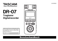
A typical system setup is shown in Figure 1-1 on page 2.<br />
The <strong>Aurora</strong> System comprises three major components:<br />
• Planar Field Generator (PFG) or Tabletop Field Generator (TTFG))<br />
• System Control Unit (SCU)<br />
• Sensor Interface Unit (SIU) (4)<br />
A host computer is also required to operate the <strong>Aurora</strong> System and associated NDI software. The<br />
host computer must be approved to IEC60950 or IEC60601 and meet the following minimum<br />
specifications:<br />
• Universal Synchronous Bus (USB) port (Alternatively, you can also use a RS-232 serial<br />
connection)<br />
Note Not all USB serial adapters are of equal quality. NDI has found the FTDI model US232R USB to RS-232 adapter<br />
cable to be reliable.<br />
• Intel or Power PC G5 Processor<br />
• 512 MB random access memory (RAM)<br />
• 75 MB free hard drive space<br />
• Operating system options:<br />
- Windows XP (32 bit)<br />
- Windows Vista (32 bit and 64 bit)<br />
<strong>Aurora</strong> <strong>V2</strong> <strong>User</strong> <strong>Guide</strong> - Revision 3 1
<strong>Aurora</strong> System Overview<br />
- Windows 7 (64 bit)<br />
- Linux 2.6.35 (Previous Linux patches that are supported are included on the CD.<br />
(Patches 33 and 34 do not work with the system.)<br />
- Mac OS X (the system was tested and verified on version 10.5.8, but may work on<br />
earlier and later versions.)<br />
• Screen resolution 1024 x 768 (1280 x 1024 recommended)<br />
Field Generator<br />
System Control Unit<br />
Note: System illustrated with Planar Field<br />
Generator. The system is also available with<br />
the Tabletop Field Generator<br />
1.2 Principles of Operation<br />
Sensor Interface Unit<br />
Figure 1-1 <strong>Aurora</strong> System<br />
USB cable to host computer (alternate<br />
option - Serial RS-232 cable)<br />
Tool containing sensors<br />
Power cable<br />
The SCU provides power to the Field Generator, which in turn produces a series of varying<br />
magnetic fields, creating a known volume of varying magnetic flux. This volume is referred to as the<br />
characterized measurement volume. The shape of the characterized measurement volume is<br />
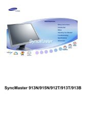
dependant on the Field Generator type and how it was characterized. The various volumes are<br />
detailed in Figure 1-2. The characterized measurement volume is the volume where data was<br />
collected and used to characterize the Field Generator. It is a subset of the detection region. (The<br />
detection region is the total volume in which the Field Generator can detect a sensor, regardless of<br />
accuracy.)<br />
2 <strong>Aurora</strong> <strong>V2</strong> <strong>User</strong> <strong>Guide</strong> - Revision 3
Planar Field<br />
Generator<br />
420<br />
120<br />
Planar Field Generator<br />
R600<br />
600<br />
Tabletop Field Generator<br />
Dome<br />
measurement<br />
volume<br />
Cube<br />
measurement<br />
volume<br />
Figure 1-2 <strong>Aurora</strong> System Measurement Volumes<br />
<strong>Aurora</strong> System Overview<br />
Sensors, typically embedded in tools, are connected to the SCU, via the SIUs. If these sensors are<br />
placed inside the measurement volume, a voltage will be induced in them, caused by the varying<br />
magnetic fields produced by the Field Generator. The characteristics of the induced voltage depend<br />
on a combination of the sensor position and orientation in the measurement volume, and the strength<br />
and phase of the varying magnetic fields.<br />
<strong>Aurora</strong> <strong>V2</strong> <strong>User</strong> <strong>Guide</strong> - Revision 3 3<br />
561<br />
50<br />
Tabletop Field<br />
Generator<br />
Measurement<br />
volume<br />
519<br />
660<br />
500<br />
All dimensions in mm<br />
500<br />
480
<strong>Aurora</strong> System Overview<br />
The SIU converts the voltages, induced in the sensors, into digital data and sends it to the SCU. The<br />
SCU analyzes the data and calculates the position and orientation of the sensors. The resultant<br />
calculation is sent to the host computer upon request from the application software.<br />
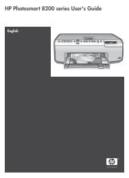
1.3 Planar Field Generator<br />
The Planar Field Generator contains a number of large coils that generate known electromagnetic<br />
fields as previously described. The measurement volumes are illustrated in Figure 1-2. The volume<br />
is projected outwards from the Field Generator’s front face, offset by 50 mm from the Field<br />
Generator. The Planar Field Generator is described in the following table and illustrated in Figure 1-<br />
3.<br />
Table 1-1 Planar Field Generator<br />
Part Description<br />
Front face<br />
Origin of the characterized measurement volume. This side is<br />
distinguishable from the others as it has both the <strong>Aurora</strong> logo and<br />
NDI logo printed on it.<br />
Mounting point Designed to attach the Field Generator to the NDI <strong>Aurora</strong> Field<br />
Generator Mounting Arm, described on page 11.<br />
Field Generator connector Connects the Field Generator cable to the SCU. The Field<br />
Generator connector is a 19 pin circular metal connector.<br />
Field Generator cable Connects the Field Generator to the SCU.<br />
M8 tapped holes (thread pitch Allows the Field Generator to be attached firmly to a fixture.<br />
1.25 mm, depth 13 mm) x 4,<br />
2 per side<br />
Front face<br />
Mounting point<br />
Field Generator connector<br />
Figure 1-3 Planar Field Generator<br />
Field Generator cable<br />
M8 tapped holes (thread<br />
pitch 1.25 mm, depth 13<br />
mm)<br />
4 <strong>Aurora</strong> <strong>V2</strong> <strong>User</strong> <strong>Guide</strong> - Revision 3
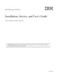
1.4 Tabletop Field Generator<br />
<strong>Aurora</strong> System Overview<br />
The Tabletop Field Generator (TTFG) is designed to be placed on a patient table, between the<br />
patient and the table. The TTFG incorporates a thin barrier that minimizes any tracking distortions<br />
caused by conductive or ferromagnetic materials located below the TTFG.<br />
The Tabletop Field Generator contains a number of large coils that generate known electromagnetic<br />
fields as previously described. The measurement volume is illustrated in Figure 1-2. The volume is<br />
projected outwards from the Field Generator’s front face, offset by 120 mm from the Field<br />
Generator. The TTFG is described in the following table and illustrated in Figure 1-4.<br />
Table 1-2 Tabletop Field Generator<br />
Part Description<br />
Front face<br />
Origin of the characterized measurement volume. The front face<br />
has both the <strong>Aurora</strong> logo and NDI logo printed on it.<br />
Carrying points Two carrying points are moulded into the TTFG case, as shown<br />
below.<br />
Field Generator connector Connects the Field Generator cable to the SCU. The Field<br />
Generator connector is a 19 pin circular metal connector.<br />
Field Generator cable (not<br />
shown)<br />
Carrying point<br />
Field Generator connector<br />
Connects the Field Generator to the SCU, via a 19 pin, 4.5 m<br />
cable.<br />
Front face<br />
Figure 1-4 Tabletop Field Generator<br />
Carrying point<br />
<strong>Aurora</strong> <strong>V2</strong> <strong>User</strong> <strong>Guide</strong> - Revision 3 5
<strong>Aurora</strong> System Overview<br />
Field Generator Labels<br />
The Field Generator type and serial number labels are located on the back of the Field Generator.<br />
They show the item ID, model and serial number of the Field Generator. See Figure 1-5 for an<br />
example of both Planar Field Generator and Tabletop Field Generator labels.<br />
1.5 System Control Unit<br />
Figure 1-5 Field Generator Labels<br />
The SCU controls the operation of the <strong>Aurora</strong> System. It acts as an interface between the system<br />
components and provides visual status indications. A brief overview of the SCU functions is as<br />
follows:<br />
• supplies power to the Field Generator and controls the Field Generator’s electromagnetic<br />
output.<br />
• collects sensor data (via the SIUs) and calculates sensor positions and orientations. It then<br />
sends the position and orientation data to the host computer (if requested).<br />
• provides visual status indications.<br />
• interfaces with the host computer.<br />
<strong>Aurora</strong> Field Generator<br />
Item ID: 610346<br />
Type: Tabletop 50-70<br />
Made in Germany<br />
Planar Field Generator Tabletop Field Generator<br />
6 <strong>Aurora</strong> <strong>V2</strong> <strong>User</strong> <strong>Guide</strong> - Revision 3
SCU Front Panel<br />
Figure 1-6 System Control Unit<br />
The SCU front panel houses the following ports and status indicators:<br />
Table 1-3 System Control Unit Front Panel<br />
<strong>Aurora</strong> System Overview<br />
Parts Description<br />
Power light (green) Lights when the SCU is powered on.<br />
Error light (amber) The error light is not yet implemented.<br />
Code light (amber) The code light is not yet implemented.<br />
Field Generator port Connects the SCU to the Field Generator cable.<br />
SIU ports Connects SIUs to the SCU, allowing communication between the<br />
system and connected tools.<br />
SIU port status lights Off - No tool is connected to this port.<br />
Amber - A tool is connected to this port, but the port has not been<br />
initialized for use.<br />
Green - A tool is connected to this port, it has been initialized, and it is<br />
ready to be used.<br />
<strong>Aurora</strong> <strong>V2</strong> <strong>User</strong> <strong>Guide</strong> - Revision 3 7
<strong>Aurora</strong> System Overview<br />
SCU Back Panel<br />
Figure 1-7 System Control Unit Front Panel<br />
The SCU back panel houses the following components:<br />
Part Description<br />
Synchronization<br />
port<br />
Table 1-4 System Control Unit Back Panel<br />
A synchronization port used to synchronize the <strong>Aurora</strong> System to other<br />
equipment.<br />
USB port A USB port used to connect the SCU to the host computer. (Preferred<br />
connection method.)<br />
RS-232 port A serial communications port used to connect the SCU to the host computer.<br />
(Alternative connection method.)<br />
Power entry<br />
module<br />
Field Generator port SIU ports (4)<br />
SIU port status lights (4)<br />
A sub-assembly that comprises a system power switch, fuses, and power<br />
cable connection port. Refer to Figure 1-9.<br />
8 <strong>Aurora</strong> <strong>V2</strong> <strong>User</strong> <strong>Guide</strong> - Revision 3
Power entry<br />
module<br />
Ventilation openings<br />
USB port<br />
Figure 1-8 System Control Unit Back Panel<br />
Power switch<br />
Fuses (2)<br />
power cable<br />
connection port<br />
Figure 1-9 System Control Unit Power Entry Module<br />
<strong>Aurora</strong> System Overview<br />
System Control Unit Labels The SCU type and serial number labels are located on the back of the<br />
SCU, and show the item ID, model, serial number and manufacture date of the SCU.<br />
Figure 1-10 System Control Unit Labels<br />
Synchronization port<br />
RS-232 port<br />
<strong>Aurora</strong> <strong>V2</strong> <strong>User</strong> <strong>Guide</strong> - Revision 3 9
<strong>Aurora</strong> System Overview<br />
1.6 Sensor Interface Unit<br />
The SIU is the interface between the sensors (embedded in tools) and the SCU. The main function of<br />
the SIU is to convert the analog signals, produced by the sensors, to digital signals. The digital<br />
signals are sent to the SCU for processing.<br />
Another function of the SIU is to increase the distance between the SCU and tools, removing the<br />
requirement for a long tool cable and keeping bulky system components away from the application<br />
space. In addition, the shorter the tool cable, the less noise will appear on the signal from the<br />
sensors. Analog signals in the tool cable (though shielded when using NDI tool cable) are still<br />
susceptible to noise, therefore the digital cable (of the SIU) is longer than the tool cable.<br />
Each SIU can support up to two 5DOF sensors, or one 6DOF sensor. The SIU also allows you to<br />
interface with sensorless tools, such as a footswitch. For more information about tools, see<br />
“Accessories” on page 10.<br />
1.7 Accessories<br />
Table 1-5 Sensor Interface Unit<br />
Part Description<br />
Tool port Connects the SIU to tools. This tool port is a 10-pin circular plastic connector.<br />
SIU connector Connects the SIU to the SCU.<br />
Figure 1-11 Sensor Interface Unit<br />
The following accessories are available for the <strong>Aurora</strong> System.<br />
Tool port<br />
Note Accessories for the <strong>Aurora</strong> System are under continual development. For a list of current accessories and<br />
applications, contact NDI.<br />
10 <strong>Aurora</strong> <strong>V2</strong> <strong>User</strong> <strong>Guide</strong> - Revision 3
Field Generator Mounting Arm<br />
<strong>Aurora</strong> System Overview<br />
The Field Generator Mounting Arm is designed to help position the Field Generator. This metal arm<br />
incorporates several articulated joints that enable you to position the Field Generator at the desired<br />
position and angle. The Field Generator Mounting Arm can be used with one of two clamps:<br />
• A general purpose clamp that attaches to a table, counter edge or T-rail<br />
• A T-rail clamp, specifically designed to fit onto the edge of a standard operating table. The<br />
T-rail clamp provides a robust and stable mounting method.<br />
Sensors<br />
Figure 1-12 Field Generator Mounting Arm and Clamps<br />
These miniature sensors enable you to create your own application specific tools, measuring both<br />
5 degrees of freedom (DOF) and 6DOF. For an explanation of degrees of freedom, refer to “Degrees<br />
of Freedom” on page 42.<br />
For details on available sensors, visit the NDI Web site at<br />
http://www.ndigital.com/medical/aurora-sensors.php or contact NDI. See page xi for contact<br />
information.<br />
Tool Cabling<br />
General purpose<br />
clamp<br />
T-rail clamp<br />
NDI supplied tool cabling is specifically designed for use with <strong>Aurora</strong> System tools.<br />
<strong>Aurora</strong> <strong>V2</strong> <strong>User</strong> <strong>Guide</strong> - Revision 3 11
<strong>Aurora</strong> System Overview<br />
General Purpose/Ready-to-Use Tools<br />
For details on available general purpose and ready-to-use tools, visit the NDI Web site at<br />
http://www.ndigital.com/medical/aurora-readyusetools.php or contact NDI. See page xi for contact<br />
information.<br />
Application Specific Tools<br />
For details on available application specific tools, visit the NDI Web site at<br />
http://www.ndigital.com/medical/aurora-minimallyinvasivetools.php or contact NDI. See page xi<br />
for contact information.<br />
Tool Developer Kit<br />
The tool developer kits contains the hardware and documentation required to begin building<br />
custom <strong>Aurora</strong> tools. For details, visit the NDI Web site at<br />
http://www.ndigital.com/medical/aurora-accessories.php or contact NDI. See page xi for<br />
contact information.<br />
Tool Cable Assembly<br />
The tool cable assembly contains everything required to build an <strong>Aurora</strong> tool from an<br />
individual sensor. For details, visit the NDI Web site at http://www.ndigital.com/medical/aurorasensors.php<br />
or contact NDI. See page xi for contact information.<br />
1.8 Service Life/Disposal<br />
The <strong>Aurora</strong> System’s expected service life is approximately eight years. To ensure environmentally<br />
responsible disposal after decommissioning, please contact NDI. See “Contact” on page xi.<br />
12 <strong>Aurora</strong> <strong>V2</strong> <strong>User</strong> <strong>Guide</strong> - Revision 3
2 Setting up the <strong>Aurora</strong> System<br />
2.1 Unpacking the <strong>Aurora</strong> System<br />
The <strong>Aurora</strong> System is shipped with:<br />
• Field Generator (Planar or Tabletop)<br />
• System Control Unit<br />
• Sensor Interface Unit (4)<br />
• Power cord<br />
• USB cable<br />
• <strong>Aurora</strong> System Product CD<br />
• Documentation<br />
Setting up the <strong>Aurora</strong> System<br />
When you unpack the <strong>Aurora</strong> System, be sure to handle all system components with care. Keep the<br />
packaging in good condition; you will need to use it if the system is ever transported.<br />
Note See "Return Procedure and Warranty" on page 78 for instructions on returning your system to NDI.<br />
2.2 General Warnings<br />
Warning!<br />
Read the following warnings before using the <strong>Aurora</strong> System, to avoid the risk of personal injury.<br />
1. Do not move the Field Generator while tracking an object. The system may produce misleading<br />
transformations which may result in possible personal injury.<br />
2. Do not place <strong>Aurora</strong> sensors, tools or Sensor Interface Units directly on the Tabletop Field<br />
Generator. Doing so will increase the risk of interference of the Tabletop Field Generator<br />
magnetic field. Such interference may produce misleading transformations which may result in<br />
possible personal injury.<br />
3. Do not disconnect the Field Generator from the system while tracking a tool. Disconnecting the<br />
Field Generator while in tracking mode will result in the system returning ‘MISSING’<br />
transformations. This can affect your application and may result in possible personal injury.<br />
4. Do not disconnect the Field Generator while the system is tracking. Disconnecting the Field<br />
Generator while in tracking mode may present an electric shock hazard, which may result in<br />
possible personal injury.<br />
5. Do not drop the Field Generator or subject it to impact. Physical damage to the Field Generator<br />
may alter its calibration and contribute to inaccurate transformations and possible personal<br />
injury.<br />
<strong>Aurora</strong> <strong>V2</strong> <strong>User</strong> <strong>Guide</strong> - Revision 3 13
Setting up the <strong>Aurora</strong> System<br />
6. Do not place the Field Generator cable inside the measurement volume, as it may create<br />
magnetic interference. This interference can contribute to inaccurate transformations and<br />
possible personal injury.<br />
7. Do not coil the Field Generator cable. The cable carries enough electric current that a magnetic<br />
field will be created when it is placed in a circular formation. This magnetic field may disturb<br />
the Field Generator’s magnetic field, contributing to inaccurate transformations and possible<br />
personal injury.<br />
8. Do not operate the Field Generator less than 10 m away from another operating Field Generator.<br />
To do so may contribute to inaccurate transformations and possible personal injury.<br />
9. Do not operate the Field Generator within 200 mm of an installed pacemaker. The magnetic<br />
field produced by the Field Generator may interfere with the operation of the pacemaker. This<br />
interference may result in personal injury.<br />
10. Do not block any of the SCU ventilation holes. If the SCU internal electronics overheat, it will<br />
perform unpredictably and may damage the system. This may contribute to inaccurate<br />
transformations and possible personal injury.<br />
11. Do not immerse any part of the SCU in water, or allow water or any other fluid to enter the<br />
equipment in any way. Liquid may damage it and may present a fire or shock hazard.<br />
12. Do not expose the <strong>Aurora</strong> System circuitry to liquids. Exposing the <strong>Aurora</strong> System circuitry to<br />
liquids may result in equipment damage and possible personal injury.<br />
13. Do not connect the SCU to any host computer that is not IEC60950 and/or IEC60601 approved.<br />
If you connect to a non-approved workstation, you may increase leakage currents beyond safe<br />
limits and risk personal injury.<br />
14. Do not use the <strong>Aurora</strong> System if any of the hardware or connectors are damaged. Such damage<br />
may affect system functions, and contribute to inaccurate transformations and possible personal<br />
injury.<br />
15. Do not kink cables, or use damaged cables. This may cause magnetic interference, or affect<br />
system functions. These may contribute to inaccurate transformations and possible personal<br />
injury.<br />
16. Always turn the power OFF before connecting or disconnecting the power and Field Generator<br />
cables to the SCU. Failure to do so may lead to personal injury.<br />
17. Do not place tool cables within 30 mm of the Field Generator cable. This interference can<br />
contribute to inaccurate transformations and possible personal injury.<br />
18. Do not use cables or accessories other than those listed in this guide, with the exception of those<br />
sold by NDI and NDI-authorized manufacturers. To do so may result in increased emissions<br />
and/or decreased immunity of the <strong>Aurora</strong> System and may lead to personal injury.<br />
19. Do not immerse any part of the SIU in water, or allow water or any other fluid to enter the<br />
equipment in any way. Liquid may damage it and may present a fire or shock hazard.<br />
20. Do not clean the system without first switching power off on all equipment, to avoid personal<br />
injury.<br />
14 <strong>Aurora</strong> <strong>V2</strong> <strong>User</strong> <strong>Guide</strong> - Revision 3
Setting up the <strong>Aurora</strong> System<br />
21. Do not expose sensors to a high magnetic field, such as a Magnetic Resonance Imaging (MRI)<br />
scanner, as they may become magnetized. Tracking with a magnetized sensor may result in<br />
incorrect transformations and possible personal injury.<br />
22. Sensors must be mounted securely within the tool body. If a sensor moves out of position,<br />
accuracy is affected. This may contribute to inaccurate transformations and possible personal<br />
injury.<br />
23. Make sure that the SCU is only connected to a mains supply that has a protective earth. Failure<br />
to do so may result in electric shock and personal injury.<br />
24. Make sure that the SCU is positioned so that the operator cannot touch the SCU and patient<br />
simultaneously. Failure to do so may result in personal injury.<br />
2.3 Mounting the Components<br />
Planar Field Generator<br />
To mount the Field Generator, proceed as follows:<br />
1. Read the warnings on page 13.<br />
2. Choose a location that minimizes interference:<br />
• If an <strong>Aurora</strong> System is being set up within 10 m of another <strong>Aurora</strong> System, there is a<br />
potential for interference when in tracking mode. For more information, contact NDI.<br />
• Make sure that the Field Generator cable is not wrapped around the Field Generator or<br />
looped anywhere along its length.<br />
• Make sure that the Field Generator is not within a radius of 1.0 m of any metal equipment,<br />
electric motors, or sources of power (with the Field Generator as the centre of this sphere).<br />
Take into account the possibility of metal in the following:<br />
- Tables, benches or worktops<br />
- Metal reinforcing rods in the floor<br />
- Computer equipment (eg monitors)<br />
- Metal struts or electrical wiring in nearby walls<br />
Note If the nature of your application environment is such that the presence of metal cannot be avoided, see “Metal<br />
Resistance” on page 48 for guidance.<br />
3. Place or mount the Field Generator on a rigid support system that can carry the full weight of the<br />
Field Generator and the Field Generator cable (2.6 kg). The support system must also be<br />
designed to minimize vibrations, as vibrations may introduce measurement errors. The Field<br />
Generator may be mounted in two ways (refer to Figure 2-1 and Figure 2-2):<br />
<strong>Aurora</strong> <strong>V2</strong> <strong>User</strong> <strong>Guide</strong> - Revision 3 15
Setting up the <strong>Aurora</strong> System<br />
a) By means of four mounting holes, two on either side of the Field Generator. The holes are<br />
M8 tapped, thread pitch 1.25 mm, depth 13 mm.<br />
b) By means of a mounting point. The mounting point allows you to use an NDI-supplied Field<br />
Generator Mounting Arm, to position the Field Generator in any direction, in a manner that<br />
helps reduce its proximity to metal disturbances. For more information, contact NDI.<br />
Note The drawing shown in Figure 2-2 is available for download from the NDI Support Site.<br />
mounting point<br />
1.0° from vertical<br />
all sides<br />
200<br />
M8 tapped holes (4)<br />
(thread pitch 1.25 mm,<br />
depth 13 mm)<br />
Figure 2-1 Planar Field Generator - Mounting Options<br />
4xM8x1.25x13<br />
Figure 2-2 Planar Field Generator - Mounting Details<br />
4. Orient the Field Generator so that the measurement volume encompasses the area of interest<br />
(area where the tools will be tracked; refer to Figure 1-2 on page 3).<br />
16 <strong>Aurora</strong> <strong>V2</strong> <strong>User</strong> <strong>Guide</strong> - Revision 3<br />
200<br />
1.0° from vertical<br />
all sides<br />
100<br />
30<br />
19<br />
35.8<br />
17<br />
7 56 72<br />
13<br />
All dimensions are in mm<br />
70.8
5. The Field Generator may be bagged or draped to fulfil sterility requirements.<br />
Tabletop Field Generator<br />
Setting up the <strong>Aurora</strong> System<br />
The Tabletop Field Generator (TTFG) is designed to be placed on a patient table, between the<br />
patient and the table. The TTFG incorporates a thin barrier that minimizes any tracking distortions<br />
caused by conductive or ferromagnetic materials located below the TTFG.<br />
To mount the Field Generator, proceed as follows:<br />
1. Read the warnings on page 13.<br />
2. Carry the Field Generator by the molded grips, located at either side of the Field Generator, see<br />
Figure 1-4 on page 5.<br />
3. Choose a location that minimizes interference from above the Field Generator:<br />
• If an <strong>Aurora</strong> System is being set up within 10 m of another <strong>Aurora</strong> System, there is a<br />
potential for interference when in tracking mode. For more information, contact NDI.<br />
• Make sure that the Field Generator cable is not lying across the Field Generator or looped<br />
anywhere along its length.<br />
• Make sure that there are no metal objects, electric motors or power sources within a 1.0 m<br />
hemisphere above the Field Generator. Take into account the possibility of metal in the<br />
following:<br />
- Tables, benches or worktops<br />
- Computer equipment (eg monitors)<br />
- Metal struts or electrical wiring in nearby walls<br />
Note If the nature of your application environment is such that the presence of metal cannot be avoided above, inside<br />
or outside the measurement volume, see “Metal Resistance” on page 48 for guidance.<br />
4. Place the Field Generator, taking into account the following requirements:<br />
• Make sure the Field Generator is placed in a horizontal position. If this is not possible the<br />
Field Generator must be secured, so it does not slide out of position.<br />
• Make sure the Field Generator is supported over its full surface area. This will prevent any<br />
deformation of the Field Generator caused by a patient’s weight. Deformation will damage<br />
the Field Generator and may result in accuracy degradation.<br />
Note The drawing shown in Figure 2-3 is available for download from the NDI Support Site.<br />
<strong>Aurora</strong> <strong>V2</strong> <strong>User</strong> <strong>Guide</strong> - Revision 3 17
Setting up the <strong>Aurora</strong> System<br />
Warning!<br />
762<br />
Top<br />
Figure 2-3 Tabletop Field Generator - Mounting Details<br />
5. Orient the Field Generator so that the measurement volume encompasses the area of interest<br />
(area where the tools will be tracked; refer to Figure 1-2 on page 3).<br />
6. The Field Generator may be bagged or draped to fulfil sterility requirements.<br />
System Control Unit<br />
1. Remove the SCU from the box.<br />
2. Place the SCU on a flat surface and make sure its ventilation openings are not blocked.<br />
3. Make sure that the cable connecting the SCU to the host computer does not come close to other<br />
cables in the <strong>Aurora</strong> System, such as the Field Generator cable.<br />
Make sure that the SCU is positioned so that the operator cannot touch the SCU and patient simultaneously.<br />
Failure to do so may result in personal injury.<br />
Note The power entry module, located at the back of the SCU, has a switching power supply with universal input<br />
voltage of 100 to 240 VAC. As such, the voltage need not be manually changed.<br />
Sensor Interface Unit<br />
1. Remove the SIUs from the box.<br />
2. Place each SIU on a flat surface and make sure that each tool cable can reach an SIU, but that<br />
tool cables do not lie close to the Field Generator cable.<br />
2.4 Cable Management<br />
It is important that you position system cables correctly to minimize interference and avoid<br />
inaccurate transformations. Relying on data derived from inaccurate transformations may cause<br />
personal injury.<br />
Read the following warnings and guidelines when you set up the system and position the units.<br />
18 <strong>Aurora</strong> <strong>V2</strong> <strong>User</strong> <strong>Guide</strong> - Revision 3<br />
34<br />
507<br />
172<br />
Cable Connection<br />
328<br />
Bottom
Warning!<br />
Setting up the <strong>Aurora</strong> System<br />
Do not place the Field Generator cable inside the measurement volume or wrap it around the Field Generator, as<br />
it may create a magnetic interference. This interference can contribute to inaccurate transformations and<br />
possible personal injury<br />
Do not place tool cables within 30 mm of the Field Generator cable. If placed this close— particularly if the cables<br />
are parallel to each other—the tool cable may become subject to electromagnetic interference. This interference<br />
can contribute to inaccurate transformations and possible personal injury.<br />
Do not coil the Field Generator cable, as it produces enough electric current that a magnetic field will be created<br />
when the cable is placed in a circular formation. This magnetic field may disturb the Field Generator's magnetic<br />
field, contributing to inaccurate transformations and possible personal injury.<br />
Make sure that the Field Generator cable is not wrapped around the Field Generator or looped<br />
anywhere along its length.<br />
Do not place SIUs close to the Field Generator or the Field Generator cable<br />
2.5 Connecting the Components<br />
Read the following cautions before you connect the <strong>Aurora</strong> System components.<br />
Caution! Do not push or pull connectors in constricted areas.<br />
Do not put heavy objects on cable connectors.<br />
Do not leave cable connectors where they can be damaged, particularly on the floor, where they can easily be<br />
stepped on.<br />
Pull connections apart by gripping the connector. Do not pull them apart by tugging on the cable as this can<br />
damage the connecting cable. Never force a connection or a disconnection.<br />
Connect the <strong>Aurora</strong> System components as follows:<br />
1. Insert the Field Generator cable connector into the Field Generator port (located on the front of<br />
the SCU). If your system includes a TTFG, connect the Field Generator cable to the TTFG.<br />
Make sure that the red alignment marks on the cable and TTFG are aligned, see Figure 2-4<br />
below.<br />
Field Generator connector<br />
alignment mark<br />
Figure 2-4 TTFG Connector<br />
2. Insert each SIU connector into one of the SIU ports (located on the front of the SCU).<br />
3. Plug each tool into its respective tool port (located on the front end of the SIU).<br />
4. Check that the tool cables are at least 30 mm from the Field Generator cable.<br />
<strong>Aurora</strong> <strong>V2</strong> <strong>User</strong> <strong>Guide</strong> - Revision 3 19
Setting up the <strong>Aurora</strong> System<br />
5. Attach one end of the USB cable to the USB port on back of the SCU.<br />
6. Attach the other end of the USB cable to a USB port on the host computer.<br />
Note An alternative method of connecting the SCU to the host computer is via RS-232 serial communications as<br />
follows:<br />
(USB and RS-232 cables cannot be used together. USB connection has priority.)<br />
1. Attach one end of the serial cable to the RS-232 port at the back of the SCU.<br />
2. Attach the other end of the serial cable to an RS-232 port or a USB port (by means of a USB serial adapter) on<br />
the host computer.<br />
7. Plug the power cable into the power entry module on the back of the SCU.<br />
Note Tools can be disconnected and reconnected into any SIU while the system is still running (hot-plugging). SIUs<br />
can also be hot-plugged into the SIU ports on the SCU.<br />
20 <strong>Aurora</strong> <strong>V2</strong> <strong>User</strong> <strong>Guide</strong> - Revision 3
3 Using the <strong>Aurora</strong> System<br />
3.1 Introduction<br />
Using the <strong>Aurora</strong> System<br />
This chapter provides information on operating the <strong>Aurora</strong> System. The information is listed under<br />
the following topics:<br />
• Powering on the <strong>Aurora</strong> System<br />
• Installing the Software<br />
• <strong>Aurora</strong> System Tools<br />
3.2 Powering on the <strong>Aurora</strong> System<br />
Warning!<br />
Before applying power to the <strong>Aurora</strong> System, make sure the system is correctly connected. Refer to<br />
“Setting up the <strong>Aurora</strong> System” on page 13. When you have connected the system, proceed as<br />
follows:<br />
Make sure that the SCU is only connected to a mains supply that has a protective earth. Failure to do so may<br />
result in electric shock and personal injury.<br />
1. Plug the SCU power cable into a power outlet.<br />
2. Turn the power on using the switch located on the back of the SCU.<br />
3. If the <strong>Aurora</strong> System is operating correctly, the following occurs:<br />
• The SCU will beep three times. The first beep is followed by two quick beeps.<br />
• The SCU power light will be lit green; the SCU error and code lights are off.<br />
• The SIU port status lights on the SCU will be lit amber if a tool is connected.<br />
Note If the system does not operate correctly refer to “Troubleshooting” on page 76.<br />
3.3 Installing the Software (Windows)<br />
The NDI software is located on the product CD that was delivered with the system. You can also<br />
download the software from the NDI Support Site at http://support.ndigital.com.<br />
Note NDI 6D Architect application software, which is used to characterize tools and create tool definition files, is<br />
located on the CD that accompanies the <strong>Aurora</strong> Tool Developer Kit, or it can be purchased separately.<br />
<strong>Aurora</strong> <strong>V2</strong> <strong>User</strong> <strong>Guide</strong> - Revision 3 21
Using the <strong>Aurora</strong> System<br />
NDI Combined API Sample<br />
This application is a sample of source code to help you better understand the API commands<br />
designed specifically for NDI measurement systems. Use this application along with the “<strong>Aurora</strong><br />
Application Program Interface <strong>Guide</strong>” when designing your own software application.<br />
To install NDI Combined API Sample, copy the contents of the “CombinedAPISample” folder from<br />
the product CD onto the host computer.<br />
NDI ToolBox<br />
NDI ToolBox is a collection of utilities that allow you to configure, upgrade, troubleshoot, and test<br />
the <strong>Aurora</strong> System. For details on using NDI ToolBox, see page 34.<br />
To install NDI ToolBox, follow the on-screen instructions from the auto-run window that appears<br />
when you insert the product CD into the drive. Alternatively, on the product CD, browse to<br />
Windows\ToolBox\ directory and double-click install.exe.<br />
Once you start the installation from the install page, a wizard appears. Follow the on-screen<br />
instructions to complete the process. The default installation location is<br />
C:\Program Files\Northern Digital Inc\ToolBox.<br />
Note The NDI ToolBox installation includes a Java virtual machine (VM) for Windows and Linux systems. The Java VM<br />
included in the NDI ToolBox installation is fully compatible with NDI ToolBox. Other versions of Java VM may<br />
cause NDI ToolBox to exhibit unusual or unpredictable behaviour.<br />
USB Drivers<br />
If you have already installed an earlier version of NDI ToolBox, the USB drivers were installed as<br />
part of that installation. By default, the drivers are located at<br />
C:\Program Files\Northern Digital Inc\ToolBox\USB Driver.<br />
The drivers are also located on the product CD in the USB Driver folder.<br />
Windows XP and Vista<br />
Install the USB drivers for Windows XP and Vista as follows:<br />
1. When you first connect the SCU to the host computer, the Found New Hardware wizard will<br />
begin automatically.<br />
2. When prompted, select the option that allows you to specify the drivers’ location.<br />
3. Browse to the folder containing the drivers, either on the host computer or on the product CD.<br />
Windows will automatically select the correct driver from the folder.<br />
4. Click Next and Finish as required to complete the installation.<br />
Note After you have selected the folder containing the USB drivers, a warning may appear, indicating that the driver<br />
has not passed Windows Logo testing. Click “Continue Anyway”.<br />
22 <strong>Aurora</strong> <strong>V2</strong> <strong>User</strong> <strong>Guide</strong> - Revision 3
Using the <strong>Aurora</strong> System<br />
5. Once the first driver is installed, the Found New Hardware wizard will launch a second time.<br />
Follow steps 2 to 4 above to install the second driver.<br />
6. The system will now appear to be connected through a virtual COM port.<br />
SCUs are interchangeable on the same USB port, without having to re-install drivers or losing the<br />
COM port previously established.<br />
Windows 7<br />
Install the USB drivers for Windows 7 as follows:<br />
Note When you first connect the SCU to the host computer, an error message may appear over the task bar. Ignore the<br />
message and complete the following steps to install the USB drivers.<br />
1. From the Windows Start menu, select Control Panel.<br />
2. In the top right hand corner of the Control Panel window, select View by: Small icons.<br />
3. From the Control panel, select Device Manager.<br />
4. Under Other Devices, right click NDI <strong>Aurora</strong> SCU.<br />
5. Select Update Driver Software..., then select Browse my computer for driver software.<br />
6. Select Program Files (x86)\Northern Digital Inc\ToolBox\USB Driver. Select Next.<br />
7. In the Windows security dialog, select Install this driver software anyway option. The first<br />
driver will install.<br />
8. After the first driver is installed, browse to Other Devices and right click USB Serial Port.<br />
9. Select Update Driver Software..., then select Browse my computer for driver software.<br />
10. Select Program Files (x86)\Northern Digital Inc\ToolBox\USB Driver. Select Next.<br />
11. In the Windows security dialog, select Install this driver software anyway option. The second<br />
driver will install.<br />
Driver installation is complete and the system will now appear to be connected through a virtual<br />
COM port.<br />
SCUs are interchangeable on the same USB port, without having to re-install drivers or losing the<br />
COM port previously established.<br />
Reassigning the Windows COM Number<br />
After the USB drivers have been installed, you can reassign the Windows COM number if desired,<br />
as follows:<br />
1. Launch Device Manager.<br />
2. Navigate to Ports (COM & LPT).<br />
3. Right-click on NDI <strong>Aurora</strong> SCU Port (COMx).<br />
4. Select the Properties pop-up menu.<br />
<strong>Aurora</strong> <strong>V2</strong> <strong>User</strong> <strong>Guide</strong> - Revision 3 23
Using the <strong>Aurora</strong> System<br />
5. Select the Port Settings tab.<br />
6. Click on the Advanced... button.<br />
7. From the dialog box that is displayed, select the COM Port Number drop-down field.<br />
8. Reassign the COM port as necessary.<br />
9. Select OK to save the changes.<br />
Windows will remember this mapping even if the SCU is unplugged from the USB port. When the<br />
SCU is reconnected to the host computer, the COM port mapping will be re-established (if it is<br />
plugged into the same USB port).<br />
3.4 Installing the Software (Linux)<br />
The NDI software is located on the product CD that was delivered with the system. You can also<br />
download the software from the NDI Support Site at http://support.ndigital.com.<br />
Note NDI 6D Architect application software, which is used to characterize tools and create tool definition files, is<br />
located on the CD that accompanies the <strong>Aurora</strong> Tool Developer Kit, or it can be purchased separately. NDI 6D<br />
Architect is written to run on a Windows operating system.<br />
NDI Combined API Sample<br />
This application is a sample of source code to help you better understand the API commands<br />
designed specifically for NDI measurement systems. Use this application along with the “<strong>Aurora</strong><br />
Application Program Interface <strong>Guide</strong>” when designing your own software application.<br />
To install NDI Combined API Sample, copy the contents of the “CombinedAPISample” folder from<br />
the product CD onto the host computer.<br />
Note The NDI Combined API Sample contains an application and source code. The application is written to run on a<br />
Windows operating system; however, you can still view the source code on a Linux system.<br />
NDI ToolBox<br />
NDI ToolBox is a collection of utilities that allow you to configure, upgrade, troubleshoot, and test<br />
the <strong>Aurora</strong> System. For details on using NDI ToolBox, see page 34.<br />
Install NDI ToolBox as follows:<br />
1. On the product CD, browse to Linux/ToolBox/install.bin.<br />
2. Follow the on-screen instructions to complete the process. The default installation location is<br />
/ToolBox.<br />
24 <strong>Aurora</strong> <strong>V2</strong> <strong>User</strong> <strong>Guide</strong> - Revision 3
Using the <strong>Aurora</strong> System<br />
Note The NDI ToolBox download includes a Java virtual machine (VM) for Windows and Linux systems. The Java VM<br />
included in the NDI ToolBox download is fully compatible with NDI ToolBox. Other versions of Java VM may<br />
cause NDI ToolBox to exhibit unusual or unpredictable behaviour.<br />
USB Drivers<br />
On Linux kernel versions 2.6 and later, USB serial devices appear as driver files "/dev/ttyUSBx"<br />
(where x is the port number). These drivers emulate a standard tty serial port and allow applications<br />
to communicate through the USB device as if it were an RS-232 or RS-422 port.<br />
For Linux kernel versions 2.6.8 through 2.6.30, NDI has supplied patches to allow the kernel to<br />
recognize and configure the <strong>Aurora</strong> System. (The patch files are located in the<br />
/usb-patch/ directory after ToolBox has been installed.) Kernel versions<br />
2.6.32 and later automatically recognize the <strong>Aurora</strong> System and no patching is required; but you<br />
must execute step 7 below.<br />
Note These instructions and the supplied patches have been tested with specific kernel versions. If you are using a<br />
different kernel version, the patch file may not work.<br />
Note Only apply the patch appropriate to your kernel version. Do not apply the patch more than once. Patches are<br />
available for 2.6.8, 2.6.20, 2.6.23 and 2.6.28. (Version 2.6.28 will also work on version 2.6.30.)<br />
The patch modifies the files ftdi_sio.c and ftdi_sio.h in the directory /usr/src/linux-2.6.x/drivers/usb/<br />
serial. The modifications are:<br />
1. ftdi_sio.h - added the define for the USB product ID for the <strong>Aurora</strong> System.<br />
2. ftdi_sio.c - alias baud rate 19.2 kbps to 1.2 Mbps and set default USB latency to 1 ms.<br />
Apply the patch to an unmodified kernel as follows:<br />
1. Log on as root user.<br />
Note Steps 2 to 5 are not required if you are using Linux kernel 2.6.32 or higher.<br />
2. Open a command shell and cd to the kernel source directory, usually /usr/src/linux.<br />
3. Create backups of the files ./drivers/usb/serial/ftdi_sio.c and ./drivers/usb/serial/ftdi_sio.h.<br />
4. patch -p1 < ftdi-usb-patch-kernel-2.6.x.patch.<br />
5. If the driver is a kernel-loadable module, apply the patch as follows:<br />
a) make modules<br />
b) make modules_install<br />
c) Restart the computer.<br />
If the driver is not a kernel-loadable module, rebuild the kernel following the instructions<br />
specific to the kernel. If you are unfamiliar with kernel rebuilding, refer to the instructions<br />
usually located in the source directory or at http://www.kernel.org/.<br />
<strong>Aurora</strong> <strong>V2</strong> <strong>User</strong> <strong>Guide</strong> - Revision 3 25
Using the <strong>Aurora</strong> System<br />
6. The SCU, when connected, will appear as “/dev/ttyUSBx”, where x is the port number.<br />
7. If you plan to access the system from a non-root user account, you will need to add the user<br />
account to the “uucp” group. It may also be necessary for you to add the user account to the<br />
“dialout” or “lock” groups. This can be done only as root user with the command “usermod –G<br />
”. (You will need to logout and login for the changes to take effect.)<br />
SCUs are interchangeable on the same USB port, without having to re-install drivers or losing the<br />
device file enumeration previously established, as long as all serial converters (NDI or other FTDIbased<br />
converters) are plugged in and enumerated in the same order.<br />
3.5 Installing the Software (Mac OS X)<br />
The NDI software is located on the product CD that was delivered with the system. You can also<br />
download the software from the NDI Support Site at http://support.ndigital.com.<br />
Note NDI 6D Architect application software, which is used to characterize tools and create tool definition files, is<br />
located on the CD that accompanies the <strong>Aurora</strong> Tool Developer Kit, or it can be purchased separately. NDI 6D<br />
Architect is written to run on a Windows operating system.<br />
System Requirements<br />
The system requirements for the Mac OS X are as follows:<br />
Hardware<br />
• A Power PC or Intel based Mac (NDI ToolBox and the USB driver are Universal Binaries).<br />
• 512 MB minimum installed memory<br />
• 15 MB free hard drive space<br />
Mac OS X Version<br />
• Mac OS X 10.4 and above. (To determine which version of Mac OS X you have, select<br />
Apple>About This Mac.)<br />
Java Version<br />
• Minimum: Java 2 Platform Standard Edition 5.0 (J2SE 5.0 build 1.5.0_xx). (If you have an<br />
older version of Java you will need to download an update from the Apple Web site.)<br />
To determine which version of Java you have, launch the Terminal application and at the command<br />
prompt, enter:<br />
java -version.<br />
Account Permissions<br />
To manage NDI software on a Mac platform you will need administrator account privileges.<br />
26 <strong>Aurora</strong> <strong>V2</strong> <strong>User</strong> <strong>Guide</strong> - Revision 3
NDI Combined API Sample<br />
Using the <strong>Aurora</strong> System<br />
This application is a sample of source code to help you better understand the API commands<br />
designed specifically for NDI measurement systems. Use this application along with the “<strong>Aurora</strong><br />
Application Program Interface <strong>Guide</strong>” when designing your own software application.<br />
To install NDI Combined API Sample, copy the contents of the “CombinedAPISample” folder from<br />
the product CD onto the host computer.<br />
Note The NDI Combined API Sample contains an application and source code. The application is written to run on a<br />
Windows operating system; however, you can still view the source code on a Mac platform.<br />
Installing and Running NDI ToolBox<br />
NDI ToolBox is a collection of utilities that allow you to configure, upgrade, troubleshoot, and test<br />
the <strong>Aurora</strong> System. For details on using NDI ToolBox, see page 34.<br />
Install NDI ToolBox as follows:<br />
1. On the product CD, locate, and open, the MacOSX folder.<br />
2. In the MacOSX folder, locate and open the ToolBox sub-folder.<br />
3. In the ToolBox folder, locate and double-click on the install.dmg file. Double click on NDI<br />
ToolBox Installer and enter your administrator password.<br />
4. Follow the on-screen instructions to complete the installation procedure.<br />
To run NDI ToolBox you can connect to the system using either:<br />
or<br />
• /dev/cu.usbserial-xxxxxxxx<br />
• /dev/tty.usbserial-xxxxxxxx<br />
The USB driver creates two possible Virtual COM Ports (VCP) connection methods to the <strong>Aurora</strong><br />
System. This is for backwards compatibility with access via BSD UNIX-style device methods. The<br />
tty methods were traditionally meant to be used for call-in connections and the cu methods for callout<br />
connections. NDI ToolBox will work correctly when either of the connections is chosen.<br />
Each NDI ToolBox Utility (Configure, Tool Tracker, Terminal Window, Console) runs in its own<br />
window. To switch between them select Command-Accent (`).<br />
USB Driver<br />
Install the USB driver as follows:<br />
1. On the product CD, locate, and open, the MacOSX folder.<br />
2. In the MacOSX folder, locate and open the USB Driver sub-folder.<br />
3. Double-click on FTDIUSBSerialDriver (NDI).pkg. (This file is also placed in the ToolBox<br />
installation folder, during ToolBox installation.)<br />
Follow the on-screen instructions to complete the installation procedure.<br />
<strong>Aurora</strong> <strong>V2</strong> <strong>User</strong> <strong>Guide</strong> - Revision 3 27
Using the <strong>Aurora</strong> System<br />
Note The driver supplied with NDI ToolBox is necessary for the creation of a VCP software interface to the <strong>Aurora</strong><br />
System. The driver is a Mac OS X kernel extension provided by FTDI and configured by NDI to support the <strong>Aurora</strong><br />
System.<br />
Activating the VCP<br />
Activate the VCP as follows:<br />
1. Restart the Mac host computer. (If you have been following the previous installation procedures,<br />
the computer will have already restarted.)<br />
2. Connect the <strong>Aurora</strong> System to one of the Mac host computer USB ports.<br />
3. From the Apple menu, select System Preferences..., then select the Network icon. Select OK<br />
on the resulting dialog box.<br />
4. If necessary, “unlock” the lock icon (located in the lower left of the dialog box) and enter your<br />
password.<br />
a) Mac OS X 10.5 and above: Click the Apply button. (This will activate the VCP.) Quit the<br />
System Preferences application.<br />
b) Mac OS X 10.4: Proceed with steps 5 and 6 below.<br />
5. From the Show drop-down menu, select Network Port Configurations. The newly created<br />
VCP for the <strong>Aurora</strong> System will be shown at the top of the list.<br />
6. Click the check box next to usbserialxxxxxxxx and click the Apply Now button. This will<br />
activate the VCP. Quit the System Preferences application.<br />
Note A unique VCP will be assigned to each USB port to which the <strong>Aurora</strong> System has been connected. This means<br />
that, if in the future, you connect the <strong>Aurora</strong> System to a different USB port you will have to perform this<br />
activation procedure again.<br />
To verify that the <strong>Aurora</strong> System is recognized by the VCP driver, launch the System Profiler<br />
application (normally found in the Utilities sub-folder within the Applications folder). Expand the<br />
Hardware tree in the left-hand Contents pane and click on the USB branch. The USB device tree<br />
will appear in the right-hand pane. The <strong>Aurora</strong> System should appear under the applicable USB Bus<br />
branch.<br />
Uninstalling Software<br />
NDI ToolBox<br />
Uninstall NDI ToolBox as follows:<br />
Navigate to Applications>NDI ToolBox and double click on NDI ToolBox Uninstaller application<br />
and follow the on-screen instructions. All related NDI ToolBox files and aliases to NDI ToolBox<br />
utilities will be removed from your system.<br />
28 <strong>Aurora</strong> <strong>V2</strong> <strong>User</strong> <strong>Guide</strong> - Revision 3
USB Driver<br />
Remove the USB driver as follows:<br />
Using the <strong>Aurora</strong> System<br />
1. Launch the Terminal application (normally found in the Applications folder in the Utilities subfolder).<br />
At the command prompt, enter the following commands:<br />
cd /System/Library/Extensions<br />
sudo rm -r FTDIUSBSerialDriver.kext<br />
cd /Library/Receipts<br />
sudo rm -r “FTDIUSBSerialDriver (NDI).pkg”<br />
2. To remove the deactivated VCPs (usbserial-xxxxxxxx) from the system:<br />
a) Unplug the <strong>Aurora</strong> System from the USB port.<br />
b) Select Apple>System Preferences...> Network.<br />
c) From the Show drop down menu, select the Network Port Configurations. The menu will<br />
display a deactivated port as greyed out. Select the port and click Delete. Confirm the<br />
deletion to remove the port.<br />
Additional Information<br />
The following sections provide additional Mac OS X specific information.<br />
Modified FTDI USB to Serial Driver<br />
If you have other devices (such as a USB to serial port converter) that also use a FTDI VCP driver<br />
then installing the driver that is included on the product CD may:<br />
1. Result in a change to the version of the driver previously installed<br />
and/or<br />
2. Possibly disable access to your other devices.<br />
The NDI configured version of the driver is based on v2.2.7 of the original FTDI VCP driver. If your<br />
device is not recognized by this version of the driver, access to your device will be disabled. Please<br />
contact NDI for assistance.<br />
Additional Installation Files<br />
During NDI ToolBox installation additional support files are placed outside the selected destination<br />
folder. The following files are placed in the /Library/Java/Extensions folder:<br />
• jai_imageio.jar<br />
• jh.jar<br />
• libpivot.jnilib<br />
• librxtxSerial.jnilib<br />
• RXTXcomm.jar<br />
<strong>Aurora</strong> <strong>V2</strong> <strong>User</strong> <strong>Guide</strong> - Revision 3 29
Using the <strong>Aurora</strong> System<br />
Lock Files and Groups<br />
NDI ToolBox uses lock files to manage requests to access the VCP connections to the <strong>Aurora</strong><br />
System. These lock files are kept in the folder /var/lock (hidden from the Finder but accessible via<br />
the Terminal application). Access to this folder is available to members of the uucp group. The user<br />
account that ran the NDI ToolBox installer was added as a member of the uucp group and the /var/<br />
lock folder was created at that time.<br />
If an alternate user account (different from the one that was used to install NDI ToolBox) runs the<br />
NDI ToolBox utilities, then make this account a member of the uucp group as follows:<br />
Note The following procedure is only applicable to Mac OS X 10.4.x. For information on Mac OS X 10.5 and higher,<br />
contact NDI for details.<br />
1. Launch the NetInfo Manager application (normally found in the Applications folder in the<br />
Utilities sub-folder).<br />
2. Use the hierarchical navigator to select groups>uucp.<br />
3. Click the lock icon and authenticate (using a userid with administrator privileges).<br />
4. Select the users property in the bottom panel.<br />
5. Select the Directory>New Value menu. Enter the userid of the user account you wish to enter.<br />
6. Click the lock icon and confirm that you wish the modification to become permanent.<br />
7. Quit the NetInfo Manager application. This will allow the alternate user account to run the NDI<br />
ToolBox utilities.<br />
Note Uninstalling NDI ToolBox does not remove the lock file folder or membership to the uucp group.<br />
NDI ToolBox Preferences<br />
When you exit NDI ToolBox, the states of each utility (window sizes, VCP last connected to, etc.)<br />
are saved to the user's home folder. These preference files are hidden from viewing in the Finder.<br />
They have names of the form .[*]Properties and can be viewed using the Terminal application.<br />
Launch the Terminal application (normally found in the Applications>Utilities sub-folder) and<br />
enter the following commands:<br />
cd ~<br />
ls -la<br />
Moving NDI ToolBox Files<br />
The NDI ToolBox utility applications (Configure and Tool Tracker) have to reside in a single folder<br />
(default is NDI ToolBox). (The Image Capture utility is not applicable to the <strong>Aurora</strong> System).<br />
Within this directory is a Java file named toolbox.jar. It contains supporting code for the utilities and<br />
as such has to be located with the utilities. NDI recommends that you do not manually move the<br />
folder from where NDI ToolBox has been installed, otherwise the uninstall application will not<br />
30 <strong>Aurora</strong> <strong>V2</strong> <strong>User</strong> <strong>Guide</strong> - Revision 3
Using the <strong>Aurora</strong> System<br />
operate correctly. If you wish to move where NDI ToolBox is installed you should first uninstall it<br />
and then re-install.<br />
USB to Serial Adapter<br />
The <strong>Aurora</strong> System has a USB interface. However, if you wish to use the RS-232 serial interface,<br />
you will have to use a USB to serial adapter.<br />
Note Not all USB serial adapters are of equal quality. NDI has found the FTDI model US232R USB to RS-232 adapter<br />
cable to be reliable.<br />
You must be aware of two scenarios that may occur:<br />
1. If the USB to serial adapter you are using is also FTDI-based and you install the NDI USB<br />
driver by mistake, you may overwrite your existing driver.<br />
2. NDI has not tested non-FTDI-based USB to serial adapters and consequently, the serial library<br />
that NDI ToolBox uses to communicate to these devices may have compatibility issues.<br />
3.6 <strong>Aurora</strong> System Tools<br />
All <strong>Aurora</strong> System tools consist of a combination of up to seven basic components:<br />
Component Description<br />
Table 3-1 Tool Components<br />
Sensors The sensor comprises a wire wound around a small metal core. The winding<br />
may be connected to a twisted pair of lead wires. A tool can contain up to<br />
two (0, 1, or 2) sensors.<br />
SROM device The SROM device stores tool specific information and characterization<br />
data. An SROM device is hardware that can be programmed only once. It is<br />
normally located inside the tool connector.<br />
Tool connector The connector houses the SROM device and provides the means to connect<br />
the tool to the SIU.<br />
Tool cable A custom conductor shielded cable that connects the sensors, switches, and<br />
LEDs to the tool connector.<br />
LEDs and switches<br />
(optional)<br />
Single input/output devices that indicate or initiate a tool function. Each tool<br />
can support up to three input/output devices.<br />
Tool body The tool body houses the sensors, LEDs and switches.<br />
Note NDI supplies sensors specifically designed and tested for use with the <strong>Aurora</strong> System. If you use sensors<br />
supplied by any other source, be aware that NDI does not guarantee the accuracy of measurements made with<br />
those sensors. Figure 3-1 shows a typical NDI sensor. (Other sensor designs are available, visit the NDI Web site<br />
at http://www.ndigital.com/medical/aurora-sensors.php, or contact NDI for details.)<br />
<strong>Aurora</strong> <strong>V2</strong> <strong>User</strong> <strong>Guide</strong> - Revision 3 31
Using the <strong>Aurora</strong> System<br />
0.5 mm<br />
Figure 3-1 A Typical Sensor<br />
Figure 3-2 shows an example of a tool incorporating each basic tool component:<br />
Tool Types<br />
Visible LED<br />
8.0 mm<br />
Tool connector<br />
SROM device (inside the<br />
tool connector)<br />
Tool cable<br />
Switch<br />
Tool body<br />
Figure 3-2 Basic Tool Components<br />
A tool can be categorized as one of several basic types, depending on the number of sensors<br />
embedded in it:<br />
Table 3-2 Categorizing Tool Types<br />
Lead wires<br />
Sensors (inside the<br />
tool body)<br />
Sensors Tool Type Sensor Placement 5DOF/6DOF<br />
0 sensorless tool (such as a<br />
foot switch)<br />
not applicable not applicable<br />
1 single sensor tool anywhere 5DOF<br />
32 <strong>Aurora</strong> <strong>V2</strong> <strong>User</strong> <strong>Guide</strong> - Revision 3
Using the <strong>Aurora</strong> System<br />
Sensors Tool Type Sensor Placement 5DOF/6DOF<br />
2 dual sensor tool not fixed relative to each other 5DOF (2)<br />
6DOF tool fixed relative to each other 6DOF<br />
Note For more information about tool design and how to build your own tools to use with the <strong>Aurora</strong> System, refer to<br />
the “<strong>Aurora</strong> Tool Design <strong>Guide</strong>”.<br />
Reference Tools<br />
A reference tool is used to allow relative measurement, rather than absolute measurement.<br />
Measuring a tool’s position and orientation is fairly straightforward as long as the following are true:<br />
1. The Field Generator does not accidentally shift. If it does shift, the global coordinate system<br />
also shifts. This change affects the perceived location of a tool within the global coordinate<br />
system, producing misleading measurement data.<br />
2. The object of interest does not accidentally shift. If you are using the <strong>Aurora</strong> System to place a<br />
tool at a specific point on the object of interest, it is very important that the object does not move<br />
with respect to the Field Generator, while you are trying to place the tool. There is no way for<br />
the system to perceive such movement, and you may end up placing the tool in the wrong<br />
location.<br />
In many application environments, shifted objects and bumped Field Generators are not uncommon<br />
occurrences. As such, the two above requirements are often difficult to meet.<br />
A reference tool is designed to be fixed to an object of interest. Once fixed, if the object moves, the<br />
reference tool will also move. Other tools can be measured relative to the reference tool, in the<br />
reference tool’s local coordinate system.<br />
The <strong>Aurora</strong> System measures the reference tool’s movement as well as the tracking tool’s<br />
movement, producing two sets of measurements. You can design your application to interpret these<br />
measurements in the following way:<br />
1. Calculate the reference tool’s movements to capture any (accidental or intentional) shifting.<br />
2. Apply these movements to the tracking tool’s position and orientation data, to correct for any<br />
accidental shifting.<br />
For a reference tool to accurately compensate movement, you should locate the reference tool close<br />
to the tracking tool’s path through the measurement volume.<br />
For more information about reference tools, see the “<strong>Aurora</strong> Tool Design <strong>Guide</strong>.”<br />
Note Reference tools are available for purchase from NDI.<br />
Table 3-2 Categorizing Tool Types<br />
<strong>Aurora</strong> <strong>V2</strong> <strong>User</strong> <strong>Guide</strong> - Revision 3 33
Tutorial: Learning to Use the <strong>Aurora</strong> System (NDI ToolBox)<br />
4 Tutorial: Learning to Use the <strong>Aurora</strong> System (NDI ToolBox)<br />
This chapter is intended as a tutorial to demonstrate the basic functionality of the <strong>Aurora</strong> System<br />
using NDI ToolBox. For more detailed information on NDI ToolBox, refer to the NDI ToolBox<br />
online help. The tutorial is designed for first time users of the system to:<br />
• set up the system to track tools,<br />
• observe error and information flags while tracking tools,<br />
• track using a reference tool, and<br />
• pivot a tool to determine the tool tip offset.<br />
4.1 Getting Started: Tracking Tools<br />
This section describes how to set up the system to track tools.<br />
To Set Up the System<br />
1. Install NDI ToolBox, as described in “Installing the Software (Windows)” on page 21,<br />
“Installing the Software (Linux)” on page 24 or “Installing the Software (Mac OS X)” on<br />
page 26.<br />
2. Set up and connect the hardware, as described in “Connecting the Components” on page 19.<br />
3. Open NDI ToolBox.<br />
4. If NDI ToolBox does not automatically connect to the system, select either:<br />
File > Connect to > (COMx) (Windows)<br />
or<br />
File > Connect to > (/dev/ttySx) (Linux)<br />
or<br />
File > Connect to > (/dev/cu.usbserial-xxxxxxxx) or (/dev/tty.usbserial-xxxxxxxx) (Mac)<br />
Note There are two possible connection methods for Mac users. This is to allow for backwards compatibility, with<br />
access via BSD UNIX-style device methods. The tty methods were traditionally meant to be used for call-in<br />
connections and the cu methods for call-out connections. NDI ToolBox will work correctly with either connection<br />
method.<br />
To Track Tools<br />
1. If the tool tracking utility is not open, click to open it.<br />
2. Connect the tool to the appropriate SIU. The system will automatically attempt to track the tool.<br />
34 <strong>Aurora</strong> <strong>V2</strong> <strong>User</strong> <strong>Guide</strong> - Revision 3
Tutorial: Learning to Use the <strong>Aurora</strong> System (NDI ToolBox)<br />
3. Move the tool throughout the characterized measurement volume. As you move the tool, the<br />
symbol representing the tool in the graphical representation will move to reflect the tool’s<br />
position.<br />
4.2 Information and Error Flags<br />
This section describes how to trigger the most common flags. Error and warning information for<br />
each connected tool is displayed in the bottom right section of the tool tracking utility.<br />
To View Information and Error Flags<br />
1. Set up the system to track tools, as described in “Getting Started: Tracking Tools” on page 34.<br />
2. For each tool, there is a tab in the bottom right section of the tool tracking utility. Select a tab to<br />
display tracking information for a particular tool.<br />
Select a tab to display<br />
tracking information for<br />
a particular tool.<br />
“Out of Volume” and “Bad Fit” flags:<br />
Figure 4-1 Tutorial: NDI ToolBox Tool Tracking Window<br />
Move the tool to the edge of the characterized measurement volume. As you move the tool to just<br />
outside the edge of the volume, NDI ToolBox will display the message “Out of Volume.” Notice that<br />
at this position, the transformation data is still displayed.<br />
Note If you are using a 6DOF tool and you place the tool such that one sensor is in the volume and other is outside the<br />
volume, NDI ToolBox will display the message “Partially Out of Volume”.<br />
Continue to move the tool outside the volume, but keep it within the detection region. Notice that the<br />
transformation data goes blank.<br />
<strong>Aurora</strong> <strong>V2</strong> <strong>User</strong> <strong>Guide</strong> - Revision 3 35
Tutorial: Learning to Use the <strong>Aurora</strong> System (NDI ToolBox)<br />
Once the tool is completely outside of the detection region, NDI ToolBox will display the message<br />
“Bad Fit” (the transformation data remains blank).<br />
4.3 Setting a Tool as Reference<br />
Figure 4-2 Tutorial: “Partially Out of Volume” Flag<br />
Figure 4-3 Tutorial: “Bad Fit” Flag<br />
This section describes how to set a tool as reference. When you set a tool as reference, all the other<br />
tools will be tracked with respect to the reference tool. For more information on reference tools, see<br />
“Reference Tools” on page 33.<br />
To Set a Tool as Reference<br />
1. Set up the system to track tools, as described in “Getting Started: Tracking Tools” on page 34.<br />
2. Connect at least two tools.<br />
3. For each connected tool, there is a tab in the bottom right section of the tool tracking utility.<br />
Select the tab corresponding to the tool you want to set as reference. (The reference tool should<br />
be a 6DOF tool.)<br />
36 <strong>Aurora</strong> <strong>V2</strong> <strong>User</strong> <strong>Guide</strong> - Revision 3
Select the tab for the<br />
tool you want to set<br />
as reference.<br />
Tutorial: Learning to Use the <strong>Aurora</strong> System (NDI ToolBox)<br />
Figure 4-4 Tutorial: Selecting a Reference Tool<br />
4. Select Track>Global Reference (or right-click on the tool tab, then select Global Reference).<br />
The reference tool will appear as a square in the graphical display. The other tool(s) will be<br />
displayed inside a square that is the colour of the reference tool. The positions and orientations<br />
of other tools will now be reported in the local coordinate system of the reference tool.<br />
Note The <strong>Aurora</strong> System still calculates the tool transformations in the coordinate system of the Field Generator. The<br />
NDI ToolBox software then calculates and reports the tool transformations with respect to the reference tool.<br />
4.4 Determining the Tool Tip Offset<br />
This section describes how to determine the tool tip offset of a probe or pointer tool by pivoting.<br />
Once NDI ToolBox has calculated the tool tip offset, it can report the position of the tip of the tool,<br />
instead of the position of the origin of the tool.<br />
To Set Up the System to Pivot<br />
You will need a divot in which to rest the tool tip while you pivot the tool. The size and shape of the<br />
divot must match the tool tip, to ensure that the tip does not move. For example, a probe with a<br />
1 mm ball tip requires a hemispherical divot with a 1 mm diameter in which to pivot.<br />
1. Set up the system to track tools, as described in “Getting Started: Tracking Tools” on page 34.<br />
2. For each connected tool there is a tab in the bottom right section of the tool tracking utility.<br />
Select the tab corresponding to the tool you want to pivot.<br />
<strong>Aurora</strong> <strong>V2</strong> <strong>User</strong> <strong>Guide</strong> - Revision 3 37
Tutorial: Learning to Use the <strong>Aurora</strong> System (NDI ToolBox)<br />
3. Click to open the Pivot dialog.<br />
Figure 4-5 Tutorial: Selecting a Tool to Pivot<br />
4. Select an appropriate start delay (typically about 5 seconds) and duration, typically about 60<br />
seconds.<br />
To Pivot the Tool<br />
Select the tab<br />
corresponding to the<br />
tool you want to pivot.<br />
1. Place the tool tip in the divot.<br />
2. Ensure that the tool is within the characterized measurement volume, and will remain within the<br />
volume throughout the pivoting procedure.<br />
3. Click Start Collection in the Pivot tool dialog.<br />
4. Slowly pivot the tool in a cone shape, at an angle of 30º to 60º from the vertical.<br />
5. Keeping the tool tip stationary, slowly pivot the tool until the specified pivot duration time has<br />
elapsed.<br />
38 <strong>Aurora</strong> <strong>V2</strong> <strong>User</strong> <strong>Guide</strong> - Revision 3
Divot size and shape match<br />
tool tip size and shape.<br />
Tutorial: Learning to Use the <strong>Aurora</strong> System (NDI ToolBox)<br />
30º to 60º<br />
Figure 4-6 Tutorial: Pivoting Technique<br />
When the pivot is complete, the Pivot Result dialog appears. If the tool is a 5DOF tool, the dialog is<br />
as shown in Figure 4-7. If the tool is a 6DOF tool, the dialog is as shown in Figure 4-8.<br />
Click Apply 5D Offset or Apply Offset as appropriate, to report the position of the tip of the tool.<br />
Figure 4-7 NDI ToolBox Software: Pivot Result (5DOF) Dialog<br />
<strong>Aurora</strong> <strong>V2</strong> <strong>User</strong> <strong>Guide</strong> - Revision 3 39
Tutorial: Learning to Use the <strong>Aurora</strong> System (NDI ToolBox)<br />
Figure 4-8 NDI ToolBox Software: Pivot Result (6DOF) Dialog<br />
40 <strong>Aurora</strong> <strong>V2</strong> <strong>User</strong> <strong>Guide</strong> - Revision 3
5 How the <strong>Aurora</strong> System Works<br />
5.1 Introduction<br />
How the <strong>Aurora</strong> System Works<br />
This chapter provides details on how the <strong>Aurora</strong> System works. The information can help increase<br />
your technical understanding of the system, but it is not absolutely necessary in order to use the<br />
system. This chapter provides information on the following topics:<br />
• Communicating with the <strong>Aurora</strong> System<br />
• Information Returned by the <strong>Aurora</strong> System<br />
• Degrees of Freedom<br />
• Coordinate Systems<br />
• Transformations<br />
• Measurement Rates<br />
• Metal Resistance<br />
• Field Generator Coils Magnetic Fields<br />
• Distortion<br />
• Error Flags and Codes<br />
5.2 Communicating with the <strong>Aurora</strong> System<br />
The <strong>Aurora</strong> System is controlled using an application program interface (API). The API is a set of<br />
commands that allow you to configure and request information from the system. The <strong>Aurora</strong> System<br />
returns information only when requested by the host computer.<br />
NDI Combined API Sample and NDI ToolBox both allow you to view the communications stream<br />
of API commands and responses between the application and the <strong>Aurora</strong> System.<br />
For details on API commands, see the “<strong>Aurora</strong> Application Program Interface <strong>Guide</strong>.”<br />
5.3 Information Returned by the <strong>Aurora</strong> System<br />
When the <strong>Aurora</strong> System is tracking tools, it returns information about those tools to the host<br />
computer (if requested). By default, the system returns:<br />
• the position of each tool’s origin, given in mm, in the coordinate system of the Field<br />
Generator (see “Global Coordinate System” on page 43).<br />
• the orientation of each tool, given in quaternion format. The quaternion values are rounded<br />
off, so the returned values may not be normalized.<br />
• an indicator value, between 0 and 9.9 (where 0 is the absence of error and 9.9 is the highest<br />
indication of error). (See “Indicator Value” on page 46.)<br />
• the status of each tool, indicating whether the tool is out of volume, partially out of<br />
volume, or missing. It also indicates whether the port handle corresponding to each tool is<br />
<strong>Aurora</strong> <strong>V2</strong> <strong>User</strong> <strong>Guide</strong> - Revision 3 41
How the <strong>Aurora</strong> System Works<br />
enabled and initialized. For more information on port handles, see the “<strong>Aurora</strong> Application<br />
Program Interface <strong>Guide</strong>.”<br />
• the frame number for each tool transformation. The frame counter starts as soon as the<br />
system is powered on, and can be reset using API commands (see the “<strong>Aurora</strong> Application<br />
Program Interface <strong>Guide</strong>” for details). The frame number returned with a transformation<br />
corresponds to the frame in which the data used to calculate that transformation was<br />
collected. (See “Measurement Rates” on page 47.)<br />
• the system status, which includes some of the system errors described in “Error Flags and<br />
Codes” on page 51.<br />
5.4 Degrees of Freedom<br />
<strong>Aurora</strong> tools are defined as either 5DOF or 6DOF, where DOF means degrees of freedom. 5DOF<br />
and 6DOF are defined as follows:<br />
• 5DOF: Five of the six degrees of freedom. Three translation values on the x, y and z-axes<br />
and any two of the three rotation values - roll, pitch and yaw.<br />
• 6DOF: Six degrees of freedom. The three translation values on the x, y and z-axes; and the<br />
three rotation values roll, pitch and yaw.<br />
The number, and placement, of sensors incorporated in a tool determines whether the tool is 5DOF<br />
or 6DOF and consequently the kind of measurements the <strong>Aurora</strong> System can perform.<br />
5DOF<br />
If a tool incorporates only one sensor, the rotation around the sensor’s z-axis (Rz) (see Figure 5-3)<br />
cannot be determined. As such, only five degrees of freedom (5DOF) can be determined for single<br />
sensor tools.<br />
For example, how much a needle physically rolls is not as important as where it is pointing and<br />
where the tip is located; as such, a needle can be a 5DOF tool, with only one sensor incorporated<br />
into its design.<br />
6DOF<br />
If a tool incorporates two sensors fixed relative to each other and ideally orthogonal, the system can<br />
determine six degrees of freedom (6DOF) for the tool. First, the system determines 5DOF<br />
information for each sensor. Next, the system combines and compares this information, applies the<br />
tool description data, and determines six degrees of freedom (6DOF) for the entire tool.<br />
For example, an ultrasound technician needs to know the location of the ultrasound probe as it<br />
moves over a subject, in order to match its findings to actual physical locations on that subject.<br />
Incorporating two sensors into the ultrasound probe produces 6DOF measurements and ensures that<br />
all translation and rotation values of the probe are captured.<br />
Note If the tool’s two sensors are fixed relative to each other in a co-linear or parallel fashion, the system will provide<br />
6DOF information for the tool, but it will not be as accurate. This is because the two sensors have a very small<br />
angle between them. As such, this tool should be considered a 5DOF tool that returns an indicator value.<br />
42 <strong>Aurora</strong> <strong>V2</strong> <strong>User</strong> <strong>Guide</strong> - Revision 3
How the <strong>Aurora</strong> System Works<br />
For more information about how the two sensors must be arranged to correctly produce 6DOF<br />
transformations for the entire tool, see the “<strong>Aurora</strong> Tool Design <strong>Guide</strong>.”<br />
5.5 Coordinate Systems<br />
This section explains the different coordinate systems that are used by the <strong>Aurora</strong> System to<br />
calculate the positions and orientations of tools. It is important to understand the nature of both<br />
global and local coordinate systems.<br />
Global Coordinate System<br />
The Field Generator uses a coordinate system with the origin located approximately on the surface<br />
of the Field Generator and the axes aligned as shown in Figure 5-1 (Planar Field Generator) or<br />
Figure 5-2 (Tabletop Field Generator). This global coordinate system is defined during manufacture<br />
and cannot be changed.<br />
The <strong>Aurora</strong> System will report the transformations of tools in the global coordinate system.<br />
However, if you are using a reference tool, software can calculate and report transformations in the<br />
local coordinate system of the reference tool. See “Reference Tools” on page 33.<br />
-y<br />
+z<br />
Approximate origin<br />
of global coordinate<br />
system (on front<br />
surface of Field<br />
Generator)<br />
-x<br />
+x<br />
Figure 5-1 Global Coordinate System (Planar Field Generator)<br />
<strong>Aurora</strong> <strong>V2</strong> <strong>User</strong> <strong>Guide</strong> - Revision 3 43<br />
+y<br />
-z<br />
Note: For clarity, the<br />
dome volume is not<br />
shown on this figure
How the <strong>Aurora</strong> System Works<br />
-x<br />
Local Coordinate System<br />
Figure 5-2 Global Coordinate System (Tabletop Field Generator)<br />
Each tool has its own local coordinate system that is defined by an origin and three axes. Local<br />
coordinate systems are an integral part of the measurement process, and the <strong>Aurora</strong> System cannot<br />
calculate a tool’s position or orientation without them.<br />
The following sections describe typical arrangements of local coordinate systems.<br />
Note For more detailed information about local coordinate systems and different tool designs, see the “<strong>Aurora</strong> Tool<br />
Design <strong>Guide</strong>.”<br />
Single Sensor Tools<br />
+z<br />
Approximate origin<br />
of global coordinate<br />
system (on front<br />
surface of Field<br />
Generator)<br />
+y<br />
-y<br />
The single sensor tool’s local coordinate system is based directly on that of its sensor. By default, the<br />
system assigns the z-axis along the sensor’s length, with an origin at the sensor’s centre. It is<br />
44 <strong>Aurora</strong> <strong>V2</strong> <strong>User</strong> <strong>Guide</strong> - Revision 3<br />
+x<br />
-z
How the <strong>Aurora</strong> System Works<br />
possible to move the origin along the z-axis. The x and y axes are not fixed, due to the inability to<br />
determine rotation about the z-axis.<br />
Figure 5-3 Sample Single Sensor Tool<br />
Note Single sensor tools do not return an indicator value. For more information about indicator values, see “Indicator<br />
Value” on page 46.<br />
Dual Sensor Tools<br />
Tool body<br />
z-axis<br />
Dual 5DOF Tools A dual 5DOF tool is essentially two single sensor tools joined to the same tool<br />
connector. As such, the tool actually has two local coordinate systems, each based on one of the<br />
sensors incorporated into its design. These local coordinate systems are determined in the same way<br />
as that of a single sensor tool.<br />
Tool connector<br />
Tool body<br />
Sensors<br />
Figure 5-4 Sample Dual 5DOF Tool<br />
Sensor<br />
6DOF Tools A 6DOF tool incorporates two sensors fixed relative to each other. 6DOF tools are<br />
assigned their own coordinate system, independent of their sensors. Each tool includes a tool<br />
definition file programmed onto the tool’s SROM device. This file defines the tool’s local<br />
coordinate system.<br />
<strong>Aurora</strong> <strong>V2</strong> <strong>User</strong> <strong>Guide</strong> - Revision 3 45<br />
Origin<br />
z-axis<br />
z-axis
How the <strong>Aurora</strong> System Works<br />
Figure 5-5 shows a sample 6DOF tool with a coordinate system independent of its sensors. When<br />
the <strong>Aurora</strong> System calculates this tool’s position and orientation, it will return only one<br />
transformation and indicator value.<br />
Sensor<br />
z-axis<br />
5.6 Transformations<br />
Figure 5-5 Sample 6DOF Tool<br />
This section describes how the <strong>Aurora</strong> System produces tool transformations.<br />
Explaining Transformations<br />
A transformation is a combination of translation and rotation values that describes the tool’s position<br />
and orientation.<br />
Once the <strong>Aurora</strong> System has calculated the position and orientation of a tool, it returns a<br />
transformation, representing the results. Transformations are returned in the following format:<br />
q0 qx qy qz Tx Ty Tz indicator_value<br />
Where:<br />
1. q0 qx qy qz represents the tool’s orientation (in quaternion format),<br />
2. Tx Ty Tz represents the tool’s position in the measurement volume (in mm) and<br />
3. indicator_value represents the transformation’s indicator value.<br />
Note The <strong>Aurora</strong> System calculates a tool’s rotation in quaternion format (q0 qx qy qz), but <strong>Aurora</strong> documentation<br />
explains a tool’s rotation in Euler format (Rx, Ry and Rz), as it is easier to visualize. NDI ToolBox software is<br />
capable of displaying a tool’s rotation using either format.<br />
Indicator Value<br />
x-axis<br />
Tool body<br />
y-axis<br />
Sensor<br />
Origin<br />
With each transformation calculated, the <strong>Aurora</strong> System returns an indicator value. The indicator<br />
value is an estimate of how well the system calculated that particular transformation. Indicator value<br />
is formatted as a unitless value scaled to fall between 0 and 9.9 (where 0 is the absence of error and<br />
9.9 is the highest indication of error).<br />
46 <strong>Aurora</strong> <strong>V2</strong> <strong>User</strong> <strong>Guide</strong> - Revision 3
How the <strong>Aurora</strong> System Works<br />
For 6DOF tools, the indicator value compares sensor measurements to the tool’s design (as<br />
described by its SROM device or tool definition file). The greater the difference between the<br />
calculated sensor positions and the known locations of the sensors within the tool, the higher the<br />
indicator value. Such discrepancies are often an indication that magnetic field disturbances are<br />
affecting the collected data.<br />
For 5DOF transformations, the indicator value is always zero.<br />
Indicator values less than 1.0 are typically considered acceptable. You should set your own<br />
thresholds, depending on the nature of your application needs.<br />
Note The indicator value is not an absolute indication of overall error, but simply an indication that your measurement<br />
may be compromised, or that you have a mismatched tool definition file.<br />
For more information about the indicator value and how to use it with your applications, see the<br />
“<strong>Aurora</strong> Application Program Interface <strong>Guide</strong>.”<br />
Producing Transformations<br />
The following procedure describes how the <strong>Aurora</strong> System produces transformations:<br />
1. When a tool is placed in the measurement volume, its sensor(s) produce data.<br />
2. The system receives the sensor data via the tool’s SIU.<br />
3. The system processes the sensor data and calculates a 5DOF transformation for each sensor that<br />
is producing information.<br />
4. The system reads the tool description data previously uploaded from the tool’s SROM device, or<br />
in a tool definition file previously uploaded from the host computer.<br />
5. The following list describes the next step the system must perform, depending on the type of<br />
tool the SROM settings describe:<br />
Single Sensor and Dual 5DOF Tools The system does not need to perform any additional steps. The<br />
5DOF transformation produced in step 3 is the final transformation for the entire tool. No indicator<br />
value is produced.<br />
6DOF Tool The system takes the two 5DOF transformations produced in step 3 and processes them<br />
using a mathematical model and the tool description data. The result is a single 6DOF<br />
transformation that reflects the position and orientation of the entire tool. Accompanying this 6DOF<br />
transformation is an indicator value.<br />
Note Sensorless tools do not produce transformations.<br />
5.7 Measurement Rates<br />
Measurement rate is the rate at which the <strong>Aurora</strong> System calculates transformations. The maximum<br />
measurement rate, or frame rate, is 40 Hz.<br />
<strong>Aurora</strong> <strong>V2</strong> <strong>User</strong> <strong>Guide</strong> - Revision 3 47
How the <strong>Aurora</strong> System Works<br />
Note The measurement rate is internal to the <strong>Aurora</strong> System and fixed; how fast your application receives and<br />
processes measurements from the <strong>Aurora</strong> System is also dependent on external factors, such as serial baud<br />
rate, API command used (TX or BX), host computer performance and software application design.<br />
When a tracking tool passes outside of the Field Generator’s measurement volume, the system may<br />
take extra time trying to find it before reporting it back as ‘MISSING’.<br />
Note It is possible to obtain faster measurement rates than those listed above, using the TSTART API command. For<br />
details on API commands, see the “<strong>Aurora</strong> Application Program Interface <strong>Guide</strong>.”.<br />
Latency<br />
The latency of the <strong>Aurora</strong> System can be defined as the answer to the question, “How old are these<br />
data?” The latency of the <strong>Aurora</strong> System is not strictly defined, because there are too many<br />
variables. It is typically 75 ms, (three frames) but can be higher.<br />
5.8 Metal Resistance<br />
Most applications that require the technology made available by the <strong>Aurora</strong> System also require<br />
metal objects: tables, tools, braces, and so forth.<br />
Although the <strong>Aurora</strong> System’s technology revolves around electromagnetic activity—activity that is<br />
affected by the presence of metal—NDI has developed ways to make the <strong>Aurora</strong> System resistant to<br />
certain metals.<br />
The following sections describe the problems caused by placing metal near an electromagnetic<br />
measurement system.<br />
About Eddy Currents<br />
An eddy current is caused when a conductive material is exposed to a dynamic magnetic field. The<br />
changing magnetic field induces a circulating flow of electrons within the conductive material,<br />
resulting in an electric current.<br />
These circulating currents (sometimes known as eddy currents) produce an electromagnetic effect of<br />
their own, creating magnetic fields that oppose the original, external magnetic field. The greater the<br />
electrical conductivity of the conductor, the greater the eddy current developed (and the greater the<br />
opposing magnetic field produced).<br />
When using an <strong>Aurora</strong> System, if a conductive metal intersects the <strong>Aurora</strong> System’s electromagnetic<br />
field, the opposing magnetic field created by resulting eddy currents disrupts that field and affects<br />
the transformation data produced.<br />
48 <strong>Aurora</strong> <strong>V2</strong> <strong>User</strong> <strong>Guide</strong> - Revision 3
Field Generator’s<br />
electromagnetic field<br />
Figure 5-6 Visualizing the Effects of Eddy Currents<br />
How the <strong>Aurora</strong> System Works<br />
One method of reducing this effect is to adjust the placement of both the tool being measured and<br />
the object producing the eddy currents. Moving the tool so that the distance between its sensors and<br />
the Field Generator is smaller than its proximity to the object creating eddy currents, may decrease<br />
the effects of the eddy currents on tool measurements.<br />
Another situation to consider is the effect of eddy currents in metallic loops. Loops may occur in<br />
structures like metallic table frames, or concrete reinforcement bars. Cutting the loops will reduce<br />
the effect of eddy currents. If cutting the loops is not an option, then locate the system to minimize<br />
the effects of the loops.<br />
The <strong>Aurora</strong> System uses special technology to take into account such effects as eddy currents. The<br />
following metal alloys work well with the <strong>Aurora</strong> System when applied in amounts similar to that<br />
used in medical tool construction:<br />
• cobalt-chrome alloy<br />
• steel DIN 1.441<br />
• titanium (TiA16V4)<br />
• 300 series stainless steel<br />
Note Tests have also shown that the <strong>Aurora</strong> System produces reasonable results with a steel DIN 1.4301 plate<br />
measuring 500 mm x 500 mm.<br />
About Ferromagnetic Metals<br />
Conductive metal object<br />
Eddy current<br />
Opposing magnetic field<br />
produced by eddy current<br />
Ferromagnetic material generally has little or no net magnetic property. However, if it is placed in a<br />
magnetic field, its domains will re-orient in parallel with that field, and may even remain re-oriented<br />
when the field is turned off. Even metals with only small amounts of ferrous material in them may<br />
have these reactions.<br />
<strong>Aurora</strong> <strong>V2</strong> <strong>User</strong> <strong>Guide</strong> - Revision 3 49
How the <strong>Aurora</strong> System Works<br />
The magnetic field produced in a ferromagnetic object attracts the external magnetic field, resulting<br />
in the external magnetic field bending towards the object itself. As such, introducing a<br />
ferromagnetic object into the <strong>Aurora</strong> Field Generator’s electromagnetic field will cause a distortion<br />
that can affect the transformation data produced. All ferrous materials will have an effect, in varying<br />
degrees, on the <strong>Aurora</strong> System’s ability to produce measurement data.<br />
Magnetic field passes through ring<br />
Magnetic field is attracted to ring<br />
Figure 5-7 Visualizing the Effects of Ferromagnetic Material<br />
The following metal alloys are examples of ferromagnetic metal that do not work well with the<br />
<strong>Aurora</strong> System:<br />
• steel DIN 1.4034<br />
• steel DIN 1.4021<br />
Metal Resistance Research<br />
NDI has developed and integrated a metal resistance technology into the <strong>Aurora</strong> System. For more<br />
information about the protocols used to test this resistance (and the results of these tests for different<br />
metals), refer to the “Accuracy Protocol to Assess the Influence of Metallic Objects on the<br />
Performances of an Electromagnetic System” research paper, available on the NDI Support Site:<br />
http://support.ndigital.com<br />
5.9 Field Generator Coils Magnetic Fields<br />
External electromagnetic field<br />
Non-ferromagnetic ring<br />
Ferromagnetic ring<br />
Figure 5-8 shows the magnetic field plot of the Field Generator coils, for both the Planar and<br />
Tabletop Field Generators. The plot shows the magnetic field strength of the coils as a function of<br />
distance to the exterior of the Field Generator.<br />
50 <strong>Aurora</strong> <strong>V2</strong> <strong>User</strong> <strong>Guide</strong> - Revision 3
How the <strong>Aurora</strong> System Works<br />
The plot also shows the recommended safety thresholds defined by the Institute for Electrical and<br />
Electronic Engineers (IEEE) Std. C95.6-2002 for both limb and head and torso (controlled<br />
environment). (“IEEE Standard for Safety Levels with Respect to Human Exposure to<br />
Electromagnetic Fields, 0-3 kHz.”)<br />
Effective Magnetic Field Strength H [A/m]<br />
10000<br />
1000<br />
100<br />
10<br />
5.10 Distortion<br />
TTFG Field<br />
1<br />
0 0.1 0.2<br />
0.3 0.4<br />
0.5<br />
Figure 5-8 Field Generators Magnetic Field Plots<br />
The <strong>Aurora</strong> System is susceptible to interference that may cause distortion of the magnetic field,<br />
resulting in inaccurate measurements. For example, interference from adjacent electrical equipment<br />
may cause distortion. To determine if other equipment is causing distortion, switch the equipment on<br />
and off while monitoring the <strong>Aurora</strong> System.<br />
Consider factors such as the magnetic properties of adjacent materials and placement of the Field<br />
Generator when determining where the system will be used.<br />
5.11 Error Flags and Codes<br />
IEEE Std. C95.6-2002, limb<br />
IEEE Std. C95.6-2002, head & torso (controlled environment)<br />
Planar FG Field<br />
Distance to Field Generator (m)<br />
This section explains the error flags and codes that the <strong>Aurora</strong> System may return. For<br />
comprehensive information on error flags and codes, refer to “The <strong>Aurora</strong> Application Program<br />
Interface <strong>Guide</strong>”.<br />
<strong>Aurora</strong> <strong>V2</strong> <strong>User</strong> <strong>Guide</strong> - Revision 3 51
How the <strong>Aurora</strong> System Works<br />
Warning!<br />
Missing and Disabled Transformations<br />
Normally, the <strong>Aurora</strong> System reports a position, orientation, and indicator value for every<br />
transformation. If the system cannot return a transformation, it will report the tool as MISSING or<br />
DISABLED.<br />
Missing Transformations<br />
The system reports a tool as MISSING if it cannot calculate a transformation for the tool. The<br />
system may be unable to calculate a transformation if:<br />
• The tool is moving too fast<br />
• There is severe interference<br />
• There is a system error (described below).<br />
• The tool is not in the detection region.<br />
By default, the system will report a tool as MISSING (even when it has calculated a transformation<br />
for the tool) if the tool is out of volume. The <strong>Aurora</strong> System is specifically designed to NOT report<br />
measurements when the tool is out of volume. You can request out of volume measurements by<br />
using reply option 0800 with the BX or TX command. You enable this additional functionality at<br />
your own discretion.<br />
When using reply option 0800 with the BX or TX command, you must take appropriate action to detect when a<br />
tool is out of volume, and determine whether this situation is detrimental to your application. If a tool is out of<br />
volume, reply option 0800 enables the system to return data that may lead to inaccurate conclusions and may<br />
cause personal injury.<br />
Disabled Transformations<br />
The system reports a tool as DISABLED if the port handle corresponding to the tool was not<br />
enabled, has been disabled, or is unoccupied. A port handle is unoccupied if it has been allocated,<br />
but you have not yet associated a tool definition file with that port handle. See the “<strong>Aurora</strong><br />
Application Program Interface <strong>Guide</strong>” for more details on port handles.<br />
Tracking Errors and Flags<br />
Many of the following errors and flags are displayed in NDI ToolBox. They are all returned with the<br />
TX and BX commands.<br />
System Status Flags<br />
System Communication Synchronization Error Indicates communication problems between internal<br />
sub-components of the system.<br />
Hardware Failure Indicates that a system hardware failure has been detected.<br />
Hardware Change Indicates that the Field Generator has been disconnected from the System Control<br />
Unit.<br />
52 <strong>Aurora</strong> <strong>V2</strong> <strong>User</strong> <strong>Guide</strong> - Revision 3
Port Status Flags<br />
How the <strong>Aurora</strong> System Works<br />
Bad Fit The bad fit flag is set if the system is unable to determine the tool position, typically because<br />
the tool is not within the detection region.<br />
Out of Volume The out of volume flag is set if a tool is completely outside the characterized<br />
measurement volume, but is still within the detection region. The flag is set regardless of whether<br />
the reply option 0800 for the TX or BX command is used. (Reply option 0800 enables the reporting<br />
of the positions of tools that are outside of the characterized measurement volume. See the “<strong>Aurora</strong><br />
Application Program Interface <strong>Guide</strong>” for details.)<br />
Partially Out of Volume The partially out of volume flag is only applicable to 6DOF tools. The<br />
partially out of volume flag will be set if one of the tool’s sensors is inside the characterized<br />
measurement volume and the other sensor is outside the characterized measurement volume, but<br />
still within the detection region.<br />
Processing Exception Indicates that a rare exception has been detected due to corrupt firmware. In<br />
this situation, please contact NDI.<br />
Broken Sensor Indicates that a sensor lead wire is broken, either along its length or at a connection<br />
point. (This bit may not always be set when a sensor lead wire breaks.)<br />
<strong>Aurora</strong> <strong>V2</strong> <strong>User</strong> <strong>Guide</strong> - Revision 3 53
External Synchronization<br />
6 External Synchronization<br />
The SCU may be used to trigger external devices and it can also be synchronized to another <strong>Aurora</strong><br />
SCU. The SCU external synchronization port is a 9 pin D-type connector.<br />
Figure 6-1 D-Type Connector Pin Arrangement<br />
This port uses open collector output signals. The connector pin designations are detailed in<br />
Table 6-1.<br />
6.1 Output Signals<br />
Table 6-1 Pin Definition for the System Control Unit Synchronization Port<br />
Pin Number Value Description<br />
1 +3.3 SCU provides up to 200 mA, +3.3 V<br />
2 Viso Optocoupler Anode<br />
3 FR IN Clock input at frame rate (high to low edge triggered)<br />
4 HF IN Clock signal input<br />
5 GND Ground<br />
6 HF OUT Clock signal output<br />
7 reserved reserved<br />
8 reserved reserved<br />
9 FR OUT Clock output at frame rate (active low)<br />
The output signals FR OUT and HF OUT are active low, open collector outputs. Each output is<br />
capable of sinking a maximum of 150 mA through an external pull-up resistor, tied to V cc<br />
(Refer to Figure 6-2). V cc must not exceed 15 V.<br />
Select the pull-up resistor such that:<br />
Rpull – up<br />
Vcc <br />
---------<br />
0.15<br />
54 <strong>Aurora</strong> <strong>V2</strong> <strong>User</strong> <strong>Guide</strong> - Revision 3
FR Out<br />
HF Out<br />
voltage<br />
+Vcc<br />
0<br />
+Vcc<br />
0<br />
Figure 6-2 Output Signal Connection<br />
The FR OUT signal goes low for 400 ns at the start of each frame.<br />
Figure 6-3 shows a timing diagram of both output signals, FR OUT and HF OUT.<br />
6.2 Input Signals<br />
1<br />
Frame Frequency<br />
400 ns Pulse<br />
2.3 MHz (continuous)<br />
Figure 6-3 External Sync Port Output Signals (With External Pull-up Resistor)<br />
External Synchronization<br />
The input signals FR IN and HF IN are galvanic isolated from the rest of the SCU electronics. They<br />
can be used to synchronize two <strong>Aurora</strong> systems. Please contact NDI technical support for details.<br />
See page xi for contact information.<br />
<strong>Aurora</strong> <strong>V2</strong> <strong>User</strong> <strong>Guide</strong> - Revision 3 55<br />
time
Maintenance<br />
7 Maintenance<br />
Warning!<br />
<strong>User</strong> maintenance of the <strong>Aurora</strong> System is limited to:<br />
• cleaning<br />
• replacing the SCU fuses<br />
Apart from replacing the SCU fuses, there are no user serviceable parts in the <strong>Aurora</strong> System. All servicing must<br />
be done by NDI. Unauthorized servicing may result in possible personal injury.<br />
7.1 Cleaning<br />
Warning!<br />
Do not expose or immerse the <strong>Aurora</strong> System to liquids, or allow fluid to enter the equipment in any way.<br />
Exposing the <strong>Aurora</strong> System to liquids may result in equipment damage, produce a fire or shock hazard, or<br />
contribute to possible personal injury.<br />
Switch off power to the system before cleaning it. Failure to do so may cause personal injury.<br />
Caution! Do not use aerosol sprays near the equipment as these sprays can damage circuitry.<br />
Do not use any solvent to clean the <strong>Aurora</strong> System. Solvents may damage the finish and remove lettering.<br />
Do not autoclave any <strong>Aurora</strong> System component. Autoclaving may damage the system.<br />
To clean the <strong>Aurora</strong> System proceed as follows:<br />
1. Wipe off dust with a dry, soft cloth.<br />
2. Remove dirt or finger marks using a damp cloth and dry immediately with a clean cloth.<br />
7.2 Replacing the System Control Unit Fuses<br />
Warning!<br />
Do not change either fuse without first disconnecting the SCU from its power source. Failure to disconnect the<br />
system may result in personal injury.<br />
1. Disconnect the SCU from the power supply.<br />
2. Release the two fuse holder tabs simultaneously with the aid of a tool (such as a screwdriver),<br />
and pull outwards. The tabs are marked with arrows for identification.<br />
56 <strong>Aurora</strong> <strong>V2</strong> <strong>User</strong> <strong>Guide</strong> - Revision 3
Fuse holder<br />
Figure 7-1 System Control Unit Power Entry Module<br />
3. Remove the fuses from the fuse drawer and verify the filament is intact.<br />
Maintenance<br />
4. Replace the fuse(s) as required, with the correct type and rating (1.00 A, 250 V, Time Delay,<br />
Breaking Capacity - High, 5 mm x 20 mm).<br />
5. Press the fuse holder inwards, ensuring that it latches correctly.<br />
<strong>Aurora</strong> <strong>V2</strong> <strong>User</strong> <strong>Guide</strong> - Revision 3 57
Calibration and Verification<br />
8 Calibration and Verification<br />
8.1 System Calibration<br />
As with all measurement and testing instruments, industry practice dictates that the <strong>Aurora</strong> System<br />
should be periodically calibrated to ensure it is operating within tolerances acceptable to the user.<br />
You must establish the system’s calibration interval on the basis of your system’s stability, purpose,<br />
and degree of usage.<br />
If, at any time, any concern regarding accuracy about the <strong>Aurora</strong> System arises, you should:<br />
1. Calibrate the <strong>Aurora</strong> System immediately.<br />
2. Analyze the system’s usual calibration interval and adjust it if necessary.<br />
3. Take all other corrective measures deemed necessary by the user in the circumstances.<br />
Note The <strong>Aurora</strong> System is highly specialized instrumentation developed by NDI. It is recommended that the <strong>Aurora</strong><br />
Field Generator be returned to the NDI facility for calibration procedures. This practice ensures that all<br />
calibrations are conducted in accordance with procedures established specifically for the <strong>Aurora</strong> System.<br />
8.2 System Verification<br />
Determining how to use the <strong>Aurora</strong> System to best suit your specific requirements should be done<br />
carefully, with much of the testing and evaluation closely tailored to your anticipated usage.<br />
For example, users often want to know the “maximum error” of the <strong>Aurora</strong> System when evaluating<br />
best practices. However, the maximum error obtained from a particular data set is not a sufficiently<br />
robust measure. The spatial detail that is lost in condensed statistical summaries is often crucial,<br />
since most measurement systems have operational regions where errors tend to be considerably<br />
lower and other regions where errors tend to be substantially higher.<br />
To learn about more valuable methods of evaluating and planning the use of the <strong>Aurora</strong> System,<br />
refer to the research paper entitled “Accuracy Assessment Protocols of Electromagnetic Tracking<br />
Systems.” You can find this document on the NDI Support Site at http://support.ndigital.com.<br />
58 <strong>Aurora</strong> <strong>V2</strong> <strong>User</strong> <strong>Guide</strong> - Revision 3
8.3 Environment Verification<br />
Calibration and Verification<br />
1. Establish a baseline for the system’s performance. This may include testing in a local<br />
environment with minimal electromagnetic field disturbances.<br />
2. Introduce each object that might disturb the characterized electromagnetic field, and objects that<br />
would be typical of the environment used in your particular application.<br />
3. Establish an indicator value threshold reflective of your particular application requirements. For<br />
more information about what an indicator value is, see “Indicator Value” on page 46.<br />
4. Placement of the Field Generator may affect the system’s performance. Consider changing the<br />
placement of the Field Generator within the environment.<br />
5. Adjust the local environment in order to simulate your system’s particular application.<br />
8.4 Field Accuracy Verification<br />
NDI recommends that you establish a field accuracy verification procedure, to monitor and confirm<br />
the system performance. You should establish a method and schedule that reflects the end use of the<br />
system.<br />
<strong>Aurora</strong> <strong>V2</strong> <strong>User</strong> <strong>Guide</strong> - Revision 3 59
Approvals and Classifications<br />
9 Approvals and Classifications<br />
9.1 Electrical Safety Approvals<br />
Standard Title<br />
UL 60601-1, First Edition<br />
(2003)<br />
CAN/CSA C22.2 No. 601.1 -<br />
M90 (R2001)<br />
CAN/CSA C22.2 No. 601.1.S1-<br />
94 (R1999)<br />
CAN/CSA C22.2 No. 601.1B-<br />
90 (R2002)<br />
IEC 60601-<br />
1:1988+A1:1991+A2:1995<br />
9.2 EMC/EMI Approvals<br />
Table 9-1 Electrical Safety Approvals<br />
Medical Electrical Equipment, Part 1: General<br />
requirements for safety<br />
Medical Electrical Equipment, Part 1: General<br />
Requirements For Safety<br />
Supplement No. 1-94 to CAN/CSA C22.2 No. 601.1 -<br />
M90<br />
Amendment 2 to CAN/CSA C22.2 No. 601.1 - M90<br />
Medical Electrical Equipment, Part 1: General<br />
Requirements for safety w/ amendments<br />
Table 9-2 EMC/EMI Approvals<br />
Standard Title<br />
FCC CFR47, Part 15, Class B, Unintentional Radiators<br />
Subpart B<br />
EN60601-1-2:2007 Medical Electrical Equipment, Part 1: General requirements<br />
for safety - Collateral standard: Electromagnetic<br />
Compatibility - Requirements and tests<br />
60 <strong>Aurora</strong> <strong>V2</strong> <strong>User</strong> <strong>Guide</strong> - Revision 3
9.3 Classifications<br />
Table 9-3 Classifications<br />
Approvals and Classifications<br />
Type Classification<br />
Electric Shock Protection Class I - protectively earthed with power from supply<br />
mains<br />
Degree of Protection from<br />
Electric Shock<br />
Type BF (Tools and Sensors)<br />
Type B (TTFG)<br />
Degree of Protection Against Ordinary equipment<br />
Ingress of Liquids<br />
Method of Sterilization or Not suitable for sterilization<br />
Disinfection<br />
Flammable Atmosphere Not suitable for use in the presence of a flammable<br />
anaesthetic mixture with air, oxygen, or nitrous oxide<br />
Mode of Operation Continuous<br />
<strong>Aurora</strong> <strong>V2</strong> <strong>User</strong> <strong>Guide</strong> - Revision 3 61
Technical Specifications<br />
10 Technical Specifications<br />
10.1 <strong>Aurora</strong> System Accuracy (Planar Field Generator)<br />
<strong>Aurora</strong> System accuracy for cube and dome volumes is detailed in the following tables. (ISO 5725-<br />
1: 1994 (E) (Accuracy (Trueness and Precision) of Measurement Methods and Results)).<br />
Note The following system accuracy results were derived using two 5DOF sensors. For the 6DOF result, the two 5DOF<br />
sensors were combined and positioned 90° to each other, with the centres of the sensors 14 mm apart.<br />
Table 10-1 Cube Volume (Planar Field Generator) - Position Errors<br />
5DOF 6DOF<br />
Position Errors RMS (mm) 95% CI (mm) RMS (mm) 95% CI (mm)<br />
Position Accuracy 0.70 1.40 0.48 0.88<br />
Position Precision 0.48 1.00 0.30 0.70<br />
Position Trueness 0.50 1.00 0.40 0.70<br />
Table 10-2 Cube Volume (Planar Field Generator) - Orientation Errors<br />
5DOF 6DOF<br />
Orientation Errors RMS (°) 95% CI (°) RMS (°) 95% CI (°)<br />
Orientation Accuracy 0.20 0.35 0.30 0.48<br />
Orientation Precision 0.07 0.15 0.20 0.40<br />
Orientation Trueness 0.20 0.32 0.25 0.45<br />
Table 10-3 Dome Volume (Planar Field Generator) - Position Errors<br />
5DOF 6DOF<br />
Position Errors RMS (mm) 95% CI (mm) RMS (mm) 95% CI (mm)<br />
Position Accuracy 1.10 2.00 0.70 1.40<br />
Position Precision 0.80 1.68 0.56 1.20<br />
Position Trueness 0.80 1.50 0.50 0.90<br />
62 <strong>Aurora</strong> <strong>V2</strong> <strong>User</strong> <strong>Guide</strong> - Revision 3
Table 10-4 Dome Volume (Planar Field Generator) - Orientation Errors<br />
Technical Specifications<br />
5DOF 6DOF<br />
Orientation Errors RMS (°) 95% CI (°) RMS (°) 95% CI (°)<br />
Orientation Accuracy 0.20 0.40 0.30 0.55<br />
Orientation Precision 0.15 0.25 0.22 0.40<br />
Orientation Trueness 0.18 0.32 0.25 0.45<br />
The graphs below illustrate that system accuracy varies relative to the distance and orientation of the<br />
(5DOF or 6DOF) sensor to the Field Generator.<br />
Note The data in both graphs are applicable to both the cube and dome volumes.<br />
Position Error [mm]<br />
Orientation Error [deg]<br />
4.0<br />
3.0<br />
2.0<br />
1.0<br />
TrueRMS<br />
PrecRMS<br />
AccuRMS<br />
Accu95% CL<br />
0.0<br />
0 200 400 600<br />
1.0<br />
0.8<br />
0.6<br />
0.4<br />
0.2<br />
0.0<br />
0 200 400 600<br />
Sensor Distance [mm]<br />
0.0<br />
0 20 40 60 80<br />
Figure 10-1 System Accuracy (Planar Field Generator) (5DOF Sensor)<br />
<strong>Aurora</strong> <strong>V2</strong> <strong>User</strong> <strong>Guide</strong> - Revision 3 63<br />
4.0<br />
3.0<br />
2.0<br />
1.0<br />
1.0<br />
0.8<br />
0.6<br />
0.4<br />
0.2<br />
0.0<br />
0 20 40 60 80<br />
Sensor Orientation [deg]<br />
Note: The plots show qualitative data to indicate trends. Do not use the plots to extract accuracy
Technical Specifications<br />
Note ‘Distance’ is defined as the length of the position vector between the origin of the Field Generator coordinate<br />
system and centre of the sensor. ‘Orientation’ is defined as the angle between the sensor axis and the position<br />
vector. (Due to symmetry, the orientation value can only vary between 0° and 90°.)<br />
Position Error [mm]<br />
Orientation Error [deg]<br />
4.0<br />
3.0<br />
2.0<br />
1.0<br />
0.0<br />
0 200 400 600<br />
1.0<br />
0.8<br />
0.6<br />
0.4<br />
0.2<br />
TrueRMS<br />
PrecRMS<br />
AccuRMS<br />
Accu95% CL<br />
0.0<br />
0 200 400 600<br />
Sensor Distance [mm]<br />
Figure 10-2 System Accuracy (Planar Field Generator) (6DOF Sensor)<br />
10.2 <strong>Aurora</strong> System Accuracy (Tabletop Field Generator)<br />
0.0<br />
0 20 40 60 80<br />
<strong>Aurora</strong> System accuracy for the dome volume is detailed in the following tables. (ISO 5725-1: 1994<br />
(E) (Accuracy (Trueness and Precision) of Measurement Methods and Results)).<br />
Note The following system accuracy results were derived using two 5DOF sensors. For the 6DOF result, the two 5DOF<br />
sensors were combined and positioned 90° to each other, with the centres of the sensors 14 mm apart.<br />
64 <strong>Aurora</strong> <strong>V2</strong> <strong>User</strong> <strong>Guide</strong> - Revision 3<br />
4.0<br />
3.0<br />
2.0<br />
1.0<br />
1.0<br />
0.8<br />
0.6<br />
0.4<br />
0.2<br />
0.0<br />
0 20 40 60 80<br />
Sensor Orientation [deg]<br />
Note: The plots show qualitative data to indicate trends. Do not use the plots to extract accuracy
Table 10-5 Dome Volume (Tabletop Field Generator) - Position Errors<br />
Table 10-6 Dome Volume (Tabletop Field Generator) - Orientation Errors<br />
Technical Specifications<br />
5DOF 6DOF<br />
Position Errors RMS (mm) 95% CI (mm) RMS (mm) 95% CI (mm)<br />
Position Accuracy 1.2 1.8 0.8 1.2<br />
Position Precision 0.7 1.3 0.4 0.9<br />
Position Trueness 1.0 1.3 0.7 0.9<br />
5DOF 6DOF<br />
Orientation Errors RMS (°) 95% CI (°) RMS (°) 95% CI (°)<br />
Orientation Accuracy 0.5 0.7 0.7 0.8<br />
Orientation Precision 0.2 0.3 0.3 0.5<br />
Orientation Trueness 0.5 0.6 0.7 0.8<br />
The graphs below illustrate that system accuracy varies relative to the distance and orientation of the<br />
(5DOF or 6DOF) sensor to the Field Generator.<br />
<strong>Aurora</strong> <strong>V2</strong> <strong>User</strong> <strong>Guide</strong> - Revision 3 65
Technical Specifications<br />
Position Error [mm]<br />
Orientation Error [deg]<br />
4.0<br />
3.0<br />
2.0<br />
1.0<br />
0.0<br />
0.0<br />
0 200 400 600 0 20 40 60 80<br />
1.4<br />
1.2<br />
1.0<br />
0.8<br />
0.6<br />
0.4<br />
0.2<br />
TrueRMS<br />
PrecRMS<br />
AccuRMS<br />
Accu95% CL<br />
0.0<br />
0.0<br />
0 200 400 600 0 20 40 60 80<br />
Sensor Distance [mm] Sensor Orientation [deg]<br />
Note: The plots show qualitative data to indicate trends. Do not use the plots to extract accuracy<br />
Figure 10-3 System Accuracy (TTFG) (5DOF Sensor)<br />
Note ‘Distance’ is defined as the length of the position vector between the origin of the Field Generator coordinate<br />
system and centre of the sensor. ‘Orientation’ is defined as the angle between the sensor axis and the position<br />
vector. (Due to symmetry, the orientation value can only vary between 0° and 90°.)<br />
66 <strong>Aurora</strong> <strong>V2</strong> <strong>User</strong> <strong>Guide</strong> - Revision 3<br />
4.0<br />
3.0<br />
2.0<br />
1.0<br />
1.4<br />
1.2<br />
1.0<br />
0.8<br />
0.6<br />
0.4<br />
0.2
Position Error [mm]<br />
Orientation Error [deg]<br />
4.0<br />
3.0<br />
2.0<br />
1.0<br />
10.3 Planar Field Generator<br />
Figure 10-4 System Accuracy (TTFG) (6DOF Sensor)<br />
Technical Specifications<br />
0.0<br />
0.0<br />
0 200 400 600 0 20 40 60 80<br />
1.4<br />
1.2<br />
1.0<br />
0.8<br />
0.6<br />
0.4<br />
0.2<br />
TrueRMS<br />
PrecRMS<br />
AccuRMS<br />
Accu95% CL<br />
0.0<br />
0.0<br />
0 200 400 600 0 20 40 60 80<br />
Sensor Distance [mm] Sensor Orientation [deg]<br />
Note: The plots show qualitative data to indicate trends. Do not use the plots to extract accuracy<br />
Dimensions<br />
(height x width x depth)<br />
Weight 2.6 kg<br />
<strong>Aurora</strong> <strong>V2</strong> <strong>User</strong> <strong>Guide</strong> - Revision 3 67<br />
4.0<br />
3.0<br />
2.0<br />
1.0<br />
1.4<br />
1.2<br />
1.0<br />
0.8<br />
0.6<br />
0.4<br />
0.2<br />
Table 10-7 Planar Field Generator Specifications<br />
200 mm x 200 mm x 71 mm<br />
Table 10-8 Planar Field Generator Operating Environmental Conditions<br />
Atmospheric Pressure 70 to 106 kPa<br />
Relative Humidity 30% to 75%<br />
Temperature +10 to +30 oC
Technical Specifications<br />
10.4 Tabletop Field Generator<br />
10.5 System Control Unit<br />
Table 10-9 Planar Field Generator Transportation and Storage Conditions<br />
Atmospheric Pressure 50 to 106 kPa<br />
Relative Humidity 10% to 90% non-condensing<br />
Temperature –10 to +50 o C<br />
Dimensions<br />
(height x width x depth)<br />
Table 10-10 Tabletop Field Generator Specifications<br />
507 mm x 762 mm x 34mm<br />
Weight 13.3 kg (without cable)<br />
Table 10-11 Tabletop Field Generator Operating Environmental Conditions<br />
Atmospheric Pressure 70 to 106 kPa<br />
Relative Humidity 30% to 75%<br />
Temperature +10 to +30 oC Table 10-12 Tabletop Field Generator Transportation and Storage Conditions<br />
Atmospheric Pressure 50 to 106 kPa<br />
Relative Humidity 10% to 90% non-condensing<br />
Temperature –10 to +50 o C<br />
Dimensions<br />
(height x width x depth)<br />
Table 10-13 System Control Unit Specifications<br />
88 mm x 235 mm x 295 mm<br />
Weight 3.4 kg<br />
Host Interface USB or RS-232<br />
Maximum Data Rate 921 Kbaud (using USB)<br />
68 <strong>Aurora</strong> <strong>V2</strong> <strong>User</strong> <strong>Guide</strong> - Revision 3
10.6 Sensor Interface Unit<br />
Table 10-13 System Control Unit Specifications (Continued)<br />
Technical Specifications<br />
Mains Power: AC Input Requirements 100 -240 V ~ (Universal input) 50/60 Hz 1.0 A<br />
Fuses 2 x T1.00, 250 V<br />
(time-delay, breaking capacity - high, 5 mm x 20 mm<br />
1.00 A, 250 V)<br />
Maximum Number of Sensor Interface Units Four<br />
Table 10-14 System Control Unit Operating Environmental Conditions<br />
Atmospheric Pressure 70 to 106 kPa<br />
Relative Humidity 30% to 75%<br />
Temperature +10 to +30 oC Table 10-15 System Control Unit Transportation and Storage Conditions<br />
Atmospheric Pressure 50 to 106 kPa<br />
Relative Humidity 10% to 90% non-condensing<br />
Temperature –10 to +50 oC Dimensions<br />
(height x width x depth)<br />
Table 10-16 Sensor Interface Unit Specifications<br />
Weight 0.250 kg<br />
Maximum Number of Sensors Two<br />
32 mm x 50 mm x 90 mm<br />
Table 10-17 Sensor Interface Unit Operating Environmental Conditions<br />
Atmospheric Pressure 70 to 106 kPa<br />
Relative Humidity 30% to 75%<br />
Temperature +10 to +30 oC <strong>Aurora</strong> <strong>V2</strong> <strong>User</strong> <strong>Guide</strong> - Revision 3 69
Technical Specifications<br />
Table 10-18 Sensor Interface Unit Transportation and Storage Conditions<br />
Atmospheric Pressure 50 to 106 kPa<br />
Relative Humidity 10% to 90% non-condensing<br />
Temperature –10 to +50 o C<br />
70 <strong>Aurora</strong> <strong>V2</strong> <strong>User</strong> <strong>Guide</strong> - Revision 3
11 Electromagnetic Compatibility<br />
11.1 ESD Precautionary Measures<br />
Electromagnetic Compatibility<br />
Care should be taken to mitigate the production of electrostatic charges. These measures can<br />
include, but are not limited to, air conditioning, humidification, conductive floor coverings, attire,<br />
etc.<br />
You should discharge any built-up static before connecting or disconnecting any cables marked with<br />
the electrostatic discharge (ESD) warning symbol shown here. To discharge any built up static,<br />
touch either the SCU metal enclosure or a large metallic object.<br />
Avoid touching accessible pins on connectors marked with the ESD symbol. You should also use an<br />
anti-static mat and bond yourself to either the SCU metal enclosure or to earth by means of an antistatic<br />
wrist strap.<br />
All staff using the <strong>Aurora</strong> System should receive instructions on the ESD warning symbol and<br />
training in basic ESD precautionary procedures. This training should include an introduction to the<br />
physics of ESD, the voltage levels that can occur in normal circumstances, and the damage caused to<br />
electronic components on contact with an electrostatically charged operator. In addition, users<br />
should be provided with an explanation of the methods used to prevent the build-up of electrostatic<br />
charges.<br />
11.2 Cables, Transducers and Accessories<br />
The following table shows the cables, transducers and accessories that may be used with the <strong>Aurora</strong><br />
System and still maintain compliance to the emissions and immunity requirements of<br />
IEC60601-1-2:2007<br />
Table 11-1 Cables, Transducers and Accessories<br />
Cable Name NDI P/N Type Shielded Notes<br />
Host Cable 120056 RS-232 Cable, F/F No The SIU and Planar Field<br />
USB Cable<br />
SIU Cable<br />
2600596<br />
8700342.000.002<br />
USB A-B Cable,<br />
5m<br />
-<br />
Yes<br />
N/A<br />
Generator cables are attached<br />
to the respective component<br />
and hence the NDI P/N refers<br />
to the component part number,<br />
Planar Field 610339 (Dome) - N/A not the cable part number.<br />
Generator<br />
Cable<br />
610340 (Cube)<br />
Tabletop Field<br />
Generator<br />
Cable<br />
Power Cord,<br />
AC (North<br />
America)<br />
610348 19-Conductor<br />
Lemo-Lemo<br />
Cable, 4.5 m<br />
7500010 3- Conductor<br />
Medical Grade<br />
The Tabletop Field Generator<br />
cable is detachable.<br />
<strong>Aurora</strong> <strong>V2</strong> <strong>User</strong> <strong>Guide</strong> - Revision 3 71<br />
N/A<br />
No
Electromagnetic Compatibility<br />
Warning!<br />
Do not use cables, transducers or accessories other than those listed in the table above, with the exception of<br />
those sold by NDI or by NDI-authorized manufacturers. To do so may result in increased emissions and/or<br />
decreased immunity of the <strong>Aurora</strong> System.<br />
11.3 Guidance and Manufacturer’s Declaration - Electromagnetic Emissions<br />
The <strong>Aurora</strong> System is intended for use in the electromagnetic environment listed below. The<br />
customer or the user of the <strong>Aurora</strong> System should make sure that it is used in such an environment.<br />
11.4 Guidance and Manufacturer’s Declaration - Electromagnetic Immunity<br />
Warning!<br />
Table 11-2 Manufacturer’s Declaration for Electromagnetic Emissions<br />
Emissions Test Compliance Electromagnetic Environment Guidance<br />
Radio Frequency (RF)<br />
emissions CISPR11<br />
Group 1 The <strong>Aurora</strong> System uses RF energy only for its<br />
internal function. Therefore, its RF emissions<br />
are very low and are not likely to cause any<br />
interference in nearby electronic equipment.<br />
RF emissions CISPR11 Class B The <strong>Aurora</strong> System is suitable for use in all<br />
Harmonic emissions<br />
IEC61000-3-2<br />
Voltage fluctuations/flicker<br />
emissions IEC61000-3-3<br />
Class A<br />
Complies<br />
establishments, including domestic<br />
establishments and those directly connected to<br />
the public low-voltage power supply network<br />
that supplies power to buildings used for<br />
domestic purposes.<br />
The <strong>Aurora</strong> System is intended for use in the electromagnetic environment listed below. The<br />
customer and/or the user of the <strong>Aurora</strong> System should ensure that it is used in such an environment.<br />
Do not use the <strong>Aurora</strong> System in the presence of other magnetic fields. To do so may lead to misleading or<br />
inaccurate transformations and possible personal injury.<br />
Do not expose sensors to a high magnetic field, such as a Magnetic Resonance Imaging (MRI) scanner, as they<br />
may become magnetized. Tracking with a magnetized sensor may result in incorrect transformations and<br />
possible personal injury.<br />
Caution! The <strong>Aurora</strong> System has not been designed or tested to be used during or following cardiac defibrillation. Cardiac<br />
defibrillation may cause system errors and/or equipment damage.<br />
72 <strong>Aurora</strong> <strong>V2</strong> <strong>User</strong> <strong>Guide</strong> - Revision 3
Immunity Test<br />
Electrostatic discharge<br />
(ESD)IEC 61000-4-2<br />
Electrical Fast Transient<br />
(EFT)/burst IEC 61000-4-4<br />
IEC 60601 Test<br />
Level<br />
±6kV contact<br />
±8kV air<br />
±2kV for power<br />
supply lines<br />
±1kV for I/O<br />
lines<br />
Surge IEC 61000-4-5 ±1kV differential<br />
mode<br />
Dips / Interruptions /Variations<br />
on power<br />
supply input IEC 61000-4-<br />
11<br />
±2kV common<br />
mode<br />
< 5% Ut for 0.5cycle<br />
40% Ut for 5cycles<br />
70% Ut for 25cycles<br />
Electromagnetic Compatibility<br />
Conducted RF<br />
IEC 61000-4-6<br />
Radiated RF<br />
IEC 61000-4-3<br />
3Vrms<br />
150 kHz to<br />
80 MHz<br />
3 V/m<br />
80 MHz to<br />
2.5 GHz<br />
Table 11-3 Electromagnetic Immunity<br />
3Vrms<br />
150 kHz to<br />
80 MHz<br />
3 V/m<br />
80 MHz to<br />
2.5 GHz<br />
* Field strengths from fixed transmitters, such as base stations for radio, cellular/cordless<br />
telephones, land mobile radios, amateur radio, AM and FM radio broadcast and TV broadcast<br />
cannot be predicted theoretically with accuracy. To assess the electromagnetic environment due to<br />
fixed RF transmitters, an electromagnetic site survey should be considered. If the measured field<br />
strength in the location in which the <strong>Aurora</strong> System is used exceeds the applicable RF compliance<br />
level above, the <strong>Aurora</strong> System should be observed to verify normal operation. If abnormal<br />
performance is observed, additional measures may be necessary, such as re-orienting or relocating<br />
the <strong>Aurora</strong> System.<br />
** Over the frequency range of 150 kHz to 80 MHz, field strengths should be less than 3V/m.<br />
Note 1. Ut is the AC mains voltage prior to the application of the test level.<br />
2. These guidelines may not apply to all situations. Electromagnetic propagation is affected by absorption and<br />
reflection from structures, objects, and people.<br />
3. At 80 MHz and 800 MHz, the higher frequency range applies.<br />
11.5 Recommended Separation Distances<br />
Recommended separation distance:<br />
3.5<br />
d = ------ <br />
3 <br />
P<br />
3.5<br />
d = ------ 80 MHz to 800 MHz<br />
3 <br />
P<br />
7<br />
d =<br />
-- P 800 MHz to 2.5 GHz<br />
3 where 'P' is the maximum output power rating of<br />
the transmitter in watts (W) according to the transmitter<br />
manufacturer and 'd' is the recommended<br />
separation distance in meters.<br />
Field strengths from fixed RF transmitters, as determined<br />
by an electromagnetic site survey* should<br />
be less than the compliance level in each frequency<br />
range.** Interference may occur in the vicinity of<br />
equipment marked with the following symbol:<br />
The <strong>Aurora</strong> System is intended for use in an electromagnetic environment in which radiated RF<br />
disturbances are controlled. The customer and/or the user of the <strong>Aurora</strong> System can help prevent<br />
electromagnetic interference by maintaining a minimum distance between portable and mobile RF<br />
74 <strong>Aurora</strong> <strong>V2</strong> <strong>User</strong> <strong>Guide</strong> - Revision 3
Electromagnetic Compatibility<br />
communications equipment (transmitters) and the <strong>Aurora</strong> System as recommended below, according<br />
to the maximum output power of the communications equipment.<br />
Table 11-4 Separation Distance - Communications Equipment and <strong>Aurora</strong> System<br />
Rated maximum output power of<br />
transmitter (watts)<br />
Separation distance according to frequency of transmitter (meters)<br />
150 kHz to 80 MHz<br />
d = (3.5 / 3) sqrt (P)<br />
80 MHz to 800 MHz<br />
d = (3.5 / 3) sqrt (P)<br />
0.01 0.117 m 0.117 m 0.233 m<br />
0.1 0.369 m 0.369 m 0.737 m<br />
1.0 1.17 m 1.17 m 2.33 m<br />
10 3.69 m 3.69 m 7.38 m<br />
100 11.67 m 11.67 m 23.33 m<br />
800 MHz to 2.5 GHz<br />
d = (7 / 3) sqrt (P)<br />
For transmitters rated at a maximum output power not listed above, the recommended separation<br />
distance d in metres (m) can be estimated using the equation applicable to the frequency of the<br />
transmitter, where P is the maximum output power rating of the transmitter in watts (W) according<br />
to the transmitter manufacturer.<br />
Note 1. At 80 MHz and 800 MHz, the higher frequency range applies.<br />
2. These guidelines may not apply to all situations. Electromagnetic propagation is affected by absorption and<br />
reflection from structures, objects, and people.<br />
<strong>Aurora</strong> <strong>V2</strong> <strong>User</strong> <strong>Guide</strong> - Revision 3 75
Troubleshooting<br />
12 Troubleshooting<br />
When I begin tracking a tool, my application reports it as ‘Missing’.<br />
There are several possibilities why a tool reports as MISSING:<br />
1. The tool has passed out of the measurement volume.<br />
2. Electromagnetic disturbances are so large that they completely interfere with the tool’s readings.<br />
Such disturbances include magnetic sources, or metal placed too close to the system.<br />
3. If you are using a tool definition file, you may be applying one that is either mismatched to the<br />
tool, or one that contains a wrong setting.<br />
4. You are moving the tool too quickly.<br />
5. Make sure that the tool cable is not parallel to the SCU power cable or the Field Generator cable.<br />
Contact NDI Technical Support if the problem persists.<br />
I am unable to initialize the <strong>Aurora</strong> System.<br />
Check your communication settings using NDI ToolBox. For more information, see the NDI<br />
ToolBox Online Help.<br />
Contact NDI Technical Support if the problem persists.<br />
The power light does not turn on after turning on my <strong>Aurora</strong> System.<br />
There are a number possibilities why your system does not power up:<br />
1. The SCU’s power cable is not properly connected to either the SCU itself, or the power source.<br />
2. The SCU fuse is blown. For information on how to check the fuse, see "Replacing the System<br />
Control Unit Fuses" on page 56.<br />
Contact NDI Technical Support if the problem persists.<br />
The transformations being returned have a very high indicator value.<br />
There are several possibilities why the system is returning a high error value:<br />
1. If you are using a tool definition file, you may be applying one that is either mismatched to the<br />
tool, or one that contains a wrong setting.<br />
2. Disturbances are influencing the system’s calculations of how the sensors are positioned. Such<br />
disturbances include magnetic sources, or metal placed too close to the system.<br />
3. The tool has been dropped or changed in some way physically, so that the positions of the<br />
sensors within the tool have been shifted.<br />
4. Make sure that the tool cable is not parallel to the SCU power cable or the Field Generator cable.<br />
5. Move the tool closer to the centre of the measurement volume; the father away from the Field<br />
Generator the tool is placed, the more susceptible it is to measurement noise. This is especially<br />
true if you are tracking a tool with respect to a reference tool. If the reference tool is placed too<br />
76 <strong>Aurora</strong> <strong>V2</strong> <strong>User</strong> <strong>Guide</strong> -- Revision 1
Troubleshooting<br />
far back in the measurement volume, not only will its own transformations be affected by<br />
measurement noise, but the original tool’s transformations being reported against the reference<br />
tool will also be affected.<br />
Contact NDI Technical Support if the problem persists.<br />
My <strong>Aurora</strong> System’s measurement volume seems to be smaller than it should be. My tools keep going<br />
MISSING before they reach the edges.<br />
If your measurement volume seems to be smaller than expected, your application environment may<br />
have elements that are interfering with the <strong>Aurora</strong> System’s electromagnetic field. For example,<br />
sources of metal can distort the measurement volume and interfere with measurements. Check your<br />
environment and test different adjustments until the measurement volume is restored.<br />
Contact NDI Technical Support if the problem persists.<br />
How do I return my <strong>Aurora</strong> System?<br />
If you ever need to return your <strong>Aurora</strong> System, you will need to obtain a Returned Materials<br />
Authorization (RMA) from NDI. See “Return Procedure and Warranty” on page 78.<br />
<strong>Aurora</strong> <strong>V2</strong> <strong>User</strong> <strong>Guide</strong> -- Revision 1 77
Return Procedure and Warranty<br />
13 Return Procedure and Warranty<br />
13.1 Return Procedure<br />
In the event that you need to return equipment to NDI for repairs, you can either fill out a Returned<br />
Materials Authorization (RMA) request form at the NDI Support Site at http://support.ndigital.com,<br />
or contact your Account Manager. NDI will contact you with RMA information and shipping<br />
instructions. Any materials you are returning to NDI should be shipped in their original packaging.<br />
You are responsible for the shipping costs of returning equipment to NDI, whether or not the<br />
equipment is covered under warranty. When the equipment is received at NDI, it will be inspected to<br />
determine whether the required repair is covered under warranty. NDI can provide you with a<br />
quotation of repair costs either before or after repairs have been made. If the equipment is covered<br />
under warranty, NDI will pay the return shipping costs. If the equipment is not covered under<br />
warranty, you are required to pay the return shipping costs.<br />
13.2 Warranty<br />
Unless otherwise agreed to in writing by NDI, the warranty is as follows, and applies only to the<br />
original purchaser.<br />
Note This warranty is also posted on the NDI Support Site at http://support.ndigital.com.<br />
Hardware<br />
NDI warrants to the Buyer that NDI’s hardware product(s) will be free from defects in material and<br />
workmanship only for a period twelve (12) months from the date such product(s) is/are shipped<br />
from NDI to the Buyer.<br />
This warranty does not apply to product(s) normally consumed in Buyer’s operations or which have<br />
a normal life inherently shorter than the above-stated warranty period. Without limiting the<br />
generality of the foregoing, the following products shall have the following warranty periods:<br />
product or components thereof which are re-chargeable batteries. . . . 90 days from shipment<br />
magnetic sensor coils . . . . . . . . . . . . . . . . . . . . . . . . . . . . . . . . . . . . . . prior to first use but no more<br />
than 90 days from shipment<br />
Software<br />
NDI’s software product(s) is/are licensed and provided “as is, where is” without warranty of any<br />
kind. NDI makes no warranties, express or implied, that the functions contained in the software<br />
product(s) will meet the Buyer’s requirements or that the operation of the programs contained<br />
therein will be error free.<br />
78 <strong>Aurora</strong> <strong>V2</strong> <strong>User</strong> <strong>Guide</strong> - Revision 3
General Provisions Applicable to Warranty<br />
Return Procedure and Warranty<br />
NDI’s obligations under this warranty shall be limited to repairing or replacing (at NDI’s option) the<br />
product(s), EXW (Incoterms 2000) NDI’s point of origin. Any original parts removed and/or<br />
replaced during any repair process shall become the property of NDI. This warranty shall apply only<br />
to the original Buyer [being that legal entity which has contracted directly with NDI for the supply<br />
of the product(s)]. Repair work shall be warranted on the same terms as stated herein except such<br />
warranty shall be for a period of sixty (60) days or for the remainder of the unexpired warranty<br />
period, whichever is longer. In respect of any product(s) supplied hereunder which are manufactured<br />
by others, NDI gives no warranty whatsoever, and the warranty given by such manufacturers, if any,<br />
shall apply.<br />
The obligations of NDI set forth in this warranty are conditional upon proper transportation,<br />
shipping, handling, storage, installation, use, maintenance and compliance with any applicable<br />
recommendations of NDI. Without limiting the generality of the foregoing, this warranty shall not<br />
apply to defects or damage resulting from: fire; misuse; abuse; accident; neglect; improper<br />
installation; improper care and/or maintenance; lack of care and/or maintenance; customer supplied<br />
software interfacing; modification or repair which is not authorized by NDI; power fluctuations;<br />
operation of hardware product(s) outside of environmental specifications; improper site preparation<br />
and maintenance; permitting any substance whatsoever to contaminate or otherwise interfere with<br />
optics; and any other cause beyond the control of NDI. The obligations set forth in this warranty are<br />
further conditional upon the Buyer promptly notifying NDI of any defect and, if required, promptly<br />
making the product(s) available for correction. NDI shall be given reasonable opportunity to<br />
investigate all claims and no product(s) shall be returned to NDI without NDI first providing the<br />
Buyer with a return material authorization number and shipping instructions. All product(s) returned<br />
to NDI shall be packaged in the containers originally used by NDI to ship the product(s) to the<br />
Buyer.<br />
NDI, for itself, its agents, contractors, employees, providers, and for any parent or subsidiary of<br />
NDI, expressly disclaims all warranties, express or implied, including, without limitation, of<br />
merchantability or fitness for a particular purpose.<br />
The foregoing warranty is the entire warranty of NDI. NDI neither assumes nor authorizes any<br />
person, purporting to act on its behalf, to modify or to change this warranty, or any other warranty or<br />
liability concerning the product(s).<br />
<strong>Aurora</strong> <strong>V2</strong> <strong>User</strong> <strong>Guide</strong> - Revision 3 79
Abbreviations and Acronyms<br />
14 Abbreviations and Acronyms<br />
Abbreviation or Acronym Definition<br />
5DOF 5 Degrees Of Freedom<br />
6DOF 6 Degrees Of Freedom<br />
AC Alternating Current<br />
AM Amplitude Modulation<br />
API Application Program Interface<br />
CD Compact Disc<br />
CI Confidence Interval<br />
DIN Deutsches Institut für Normung (German Institute for<br />
Standardization)<br />
EMC Electromagnetic Compatibility<br />
EMI Electromagnetic Interference<br />
ESD Electrostatic Discharge<br />
FCC Federal Communications Commission<br />
FG Field Generator<br />
FM Frequency Modulation<br />
IEEE Institute of Electrical and Electronic Engineers<br />
LED Light Emitting Diode<br />
MRI Magnetic Resonance Imaging<br />
NDI Northern Digital Inc.<br />
PFG Planar Field Generator<br />
RAM Random Access Memory<br />
RF Radio Frequency<br />
RMA Returned Materials Authorization<br />
RMS Root Mean Square<br />
SCU System Control Unit<br />
SIU Sensor Interface Unit<br />
SROM Serial Read Only Memory<br />
TTFG Tabletop Field Generator<br />
UL Underwriters Laboratories Inc.<br />
USB Universal Synchronous Bus<br />
80 <strong>Aurora</strong> <strong>V2</strong> <strong>User</strong> <strong>Guide</strong> - Revision 3
15 Equipment Symbols<br />
The following table explains the symbols found on <strong>Aurora</strong> System hardware:<br />
Table 15-1 Equipment Symbols<br />
Symbol Meaning Location<br />
Warning<br />
(to avoid personal injury, consult accompanying documentation)<br />
SIU<br />
Read accompanying documentation SCU<br />
Equipment Symbols<br />
Power On SCU (Switch)<br />
Power Off SCU (Switch)<br />
Fuse SCU<br />
Alternating current SCU<br />
RS-232 serial communication port SCU<br />
Synchronization port SCU<br />
USB port SCU<br />
Field Generator cable port SCU<br />
Sensor Interface Unit cable port SCU, SIU<br />
Tool cable port SIU<br />
Type B equipment TTFG<br />
Type BF equipment SCU<br />
Fragile Packaging<br />
Temperature limit Packaging<br />
<strong>Aurora</strong> <strong>V2</strong> <strong>User</strong> <strong>Guide</strong> - Revision 3 81
Equipment Symbols<br />
Table 15-1 Equipment Symbols (Continued)<br />
Symbol Meaning Location<br />
Keep away from rain Packaging<br />
Maximum permitted stacking load Packaging<br />
Maximum permitted number of stacked packages Packaging<br />
Atmospheric pressure limit Packaging<br />
Humidity limit Packaging<br />
82 <strong>Aurora</strong> <strong>V2</strong> <strong>User</strong> <strong>Guide</strong> - Revision 3
16 Declaration of Conformity<br />
Declaration of Conformity<br />
<strong>Aurora</strong> <strong>V2</strong> <strong>User</strong> <strong>Guide</strong> - Revision 3 83
Glossary<br />
17 Glossary<br />
5DOF<br />
Five of the six degrees of freedom needed to uniquely define the position and orientation of a rigid<br />
body in space. Three translation values on the x, y and z-axes and any two of the three rotation<br />
values, in general - roll, pitch and yaw.<br />
6DOF<br />
Six degrees of freedom needed to uniquely define the position and orientation of a rigid body in<br />
space. The three translation values on the x, y, and z-axes; and the three rotation values roll, pitch<br />
and yaw.<br />
calibration<br />
Calibration is the process of establishing, under specified conditions, the relationship between<br />
values produced by an NDI measurement system and corresponding known values established by a<br />
device that is traceable to a national standard.<br />
characterization (Field Generator)<br />
Characterizing a Field Generator is a manufacturing process used to determine and define the<br />
specific physical parameters of each Field Generator.<br />
characterization (tool)<br />
Characterizing a tool is the process of creating its tool definition file (.rom).<br />
characterized measurement volume<br />
The characterized measurement volume is the volume within the detection region where accuracy is<br />
within specified limits. NDI cannot guarantee measurement accuracy outside this region.<br />
detection region<br />
The detection region is the total volume in which an NDI measurement system can detect a marker/<br />
sensor, regardless of accuracy.<br />
dual sensor tool<br />
A dual sensor tool contains two sensors. If the sensors are affixed relative to each other inside this<br />
tool, the system is able to measure the transformations of the tool in 6DOF.<br />
Electromagnetic Compatibility (EMC)<br />
Electromagnetic Compatibility (EMC) is the extent to which a piece of hardware will both interfere<br />
with other equipment and tolerate electrical interference from other equipment.<br />
84 <strong>Aurora</strong> <strong>V2</strong> <strong>User</strong> <strong>Guide</strong> - Revision 3
Electromagnetic Interference (EMI)<br />
Glossary<br />
Electromagnetic Interference (EMI) are electromagnetic waves that emit from natural sources or<br />
electrical and electronic devices.<br />
Euler rotation<br />
An Euler rotation is a mathematical method of describing a rotation in three dimensions: the rotation<br />
of the object around each axis (Rx, Ry, and Rz), applied in a specific order.<br />
Euler transformation<br />
An Euler transformation is a mathematical method of describing translations and rotations in three<br />
dimensions. Six values are reported for an Euler transformation: the three translational values in the<br />
x, y, and z-axes; and rotations around each of the axes, Rx, Ry, and Rz.<br />
Field Generator<br />
The Field Generator is the component of the <strong>Aurora</strong> System that generates the electromagnetic field.<br />
Field Generator cable<br />
The Field Generator cable connects the Field Generator to the System Control Unit.<br />
Field Generator port<br />
The Field Generator port connects the System Control Unit to the Field Generator.<br />
global coordinate system<br />
The global coordinate system is an NDI measurement system's coordinate system. The global<br />
coordinate system is used by the measurement system as a frame of reference against which tool<br />
transformations are reported. By default, the global coordinate system's origin is set at the Field<br />
Generator.<br />
indicator value<br />
The indicator value is a unitless estimate of how well the system calculated a particular<br />
transformation.<br />
local coordinate system<br />
A local coordinate system is a coordinate system assigned to a specific tool.<br />
local frame of reference<br />
A local frame of reference is a reference tool's local coordinate system.<br />
<strong>Aurora</strong> <strong>V2</strong> <strong>User</strong> <strong>Guide</strong> - Revision 3 85
Glossary<br />
measurement volume<br />
See characterized measurement volume.<br />
missing<br />
If the system cannot determine the location of a sensor or a transformation of a rigid body/tool, that<br />
sensor or rigid body/tool is considered missing.<br />
quaternion transformation<br />
A quaternion transformation is a mathematical method of describing a change in position and<br />
orientation in three dimensions. Seven values are reported for a quaternion transformation: the three<br />
translational values in the x, y, and z axes; qx, qy and qz form a vector and q0 indicates the amount<br />
of rotation about that vector.<br />
reference tool<br />
A reference tool is a tool whose local coordinate system is used as a frame of reference in which<br />
other tools are reported/measured.<br />
Rx, Ry, Rz<br />
The terms Rx, Ry, and Rz refer to angles of rotation around the x, y and z-axes respectively.<br />
sensor<br />
A sensor is a coil of wire with two lead wires whose position can be determined in 5DOF by the<br />
<strong>Aurora</strong> System.<br />
Sensor Interface Unit (SIU)<br />
The SIU is the component of the <strong>Aurora</strong> System that connects tools to the System Control Unit<br />
(SCU).<br />
sensorless tools<br />
Tools that have no sensors, and cannot have their position determined. For example, a foot switch.<br />
Sensorless tools have GPIO lines that need to be recognized by the system.<br />
single sensor tool<br />
A single sensor tool contains one sensor. This tool can only provide 5DOF position information.<br />
SROM device<br />
An SROM device is a memory device located inside a wired tool. A tool definition file can be<br />
programmed into the SROM device so that the tool can carry its own information for automatic<br />
retrieval by an NDI measurement system.<br />
86 <strong>Aurora</strong> <strong>V2</strong> <strong>User</strong> <strong>Guide</strong> - Revision 3
SROM image file<br />
see tool definition file<br />
System Control Unit (SCU)<br />
Glossary<br />
The System Control Unit (SCU) controls the <strong>Aurora</strong> System. The SCU powers and directs the Field<br />
Generator's output, collects measurement data from tools, and calculates transformations. It also<br />
communicates with the host computer.<br />
tool definition file<br />
A tool definition file stores information about a tool. This includes information such as the<br />
placement of the tool's sensors, the location of its origin, and its manufacturing data. A tool<br />
definition file is formatted as a .rom file.<br />
tool origin<br />
The tool origin is the origin of the tool's local coordinate system.<br />
transformation<br />
A transformation is a combination of translation and rotation values that describe the location of the<br />
tool in position and orientation. See also Euler transformation, quaternion transformation.<br />
<strong>Aurora</strong> <strong>V2</strong> <strong>User</strong> <strong>Guide</strong> - Revision 3 87
Index<br />
Numerics<br />
5DOF, 42<br />
6DOF, 42<br />
6DOF tools, 45<br />
A<br />
account permissions<br />
Max, 26<br />
accuracy, 62, 64<br />
API commands<br />
BX, 52, 53<br />
TX, 52, 53<br />
approvals, 60<br />
<strong>Aurora</strong> System<br />
accuracy, 62, 64<br />
cleaning, 56<br />
declaration of conformity, 83<br />
B<br />
back panel, 8<br />
BX command, 52, 53<br />
C<br />
cables, 71<br />
calibration, 58<br />
cautions, x<br />
classifications, 61<br />
cleaning, 56<br />
communication synchronization error, 52<br />
D<br />
declaration of conformity, 83<br />
decontamination policy, 78<br />
disclaimers, x<br />
distortion, 50<br />
drivers for Host USB Converter<br />
Linux, 25<br />
Windows, 22, 24<br />
dual 5DOF, 45<br />
dual sensor tools, 45<br />
<strong>Aurora</strong> <strong>V2</strong> <strong>User</strong> <strong>Guide</strong> - Revision 3 88<br />
E<br />
Index<br />
eddy current, 48<br />
electromagnetic compatibility<br />
cables, transducers and accessories, 71<br />
ESD precautionary measures, 71<br />
Guidance and Manufacturer’s Declaration, 72<br />
recommended separation distances, 74<br />
electromagnetic emissions, 72<br />
electromagnetic immunity, 72<br />
EMC, 80<br />
EMI, 80<br />
errors<br />
system communication synchronization, 52<br />
ESD precautionary measures, 71<br />
euler, 46<br />
external synchronization, 54<br />
F<br />
ferromagnetic material, 49<br />
Field Generator<br />
Field Generator cable, 4, 5<br />
Field Generator connector, 4, 5<br />
Tabletop, 5, 17<br />
technical specifications, 67<br />
transporting and storing conditions, 67<br />
frame number, 42<br />
front face, 4, 5<br />
front panel, 7<br />
fuse, 8, 56, 69<br />
H<br />
hardware requirements Mac, 26<br />
hardware warranty, 78<br />
Host USB Converter<br />
drivers<br />
Linux, 25<br />
Windows, 22, 24<br />
humidity, 67, 68, 69
I<br />
indicator value, 41, 46<br />
installing<br />
Host USB Converter drivers<br />
Linux, 25<br />
Windows, 22, 24<br />
host USB converter drivers<br />
Mac, 27<br />
NDI ToolBox<br />
Linux, 24<br />
Mac, 27<br />
Windows, 22<br />
J<br />
Java version<br />
Mac, 26<br />
Java VM, 22<br />
M<br />
Mac<br />
account permissions, 26<br />
hardware requirements, 26<br />
Java version, 26<br />
moving toolbox files, 30<br />
OS version, 26<br />
software uninstalling, 28<br />
toolbox preferences, 30<br />
USB driver installation, 27<br />
measurement rates, 47<br />
measurement volume, 2, 3, 16, 18, 53, 76<br />
metal resistance, 48, 50<br />
missing, 41, 76<br />
mounting post, 4, 5<br />
N<br />
NDI, 80<br />
NDI 6D Architect, 21, 24, 26<br />
NDI CAPI Sample<br />
installing<br />
Linux, 24, 27<br />
Windows, 22, 31<br />
NDI ToolBox<br />
installing<br />
Linux, 24<br />
Windows, 22<br />
<strong>Aurora</strong> <strong>V2</strong> <strong>User</strong> <strong>Guide</strong> - Revision 3 89<br />
O<br />
orientation of tool, 41<br />
OS version Mac, 26<br />
out of volume, 41, 53<br />
P<br />
partially out of volume, 41, 53<br />
port status lights, 7<br />
position of tool, 41<br />
power entry module, 8<br />
processing exception, 53<br />
Q<br />
quaternion, 41, 46, 86<br />
R<br />
recommended separation distances, 74<br />
return procedure, 78<br />
RF, 80<br />
RMA number, 78<br />
RS-232 port, 8<br />
S<br />
SCU<br />
back panel, 8<br />
front panel, 7<br />
sensor, 3, 11, 31<br />
Sensor Interface Unit<br />
transportation and storage conditions, 70<br />
SIU port status, 7<br />
software<br />
installing<br />
Linux, 24<br />
Mac, 26<br />
Windows, 21<br />
warranty, 78<br />
status<br />
system, 42, 52<br />
tool, 41<br />
synchronization error, 52<br />
synchronization port, 8, 54<br />
input signals, 55<br />
output signals, 54<br />
Index
Index<br />
system<br />
accuracy, 62, 64<br />
communication synchronization error, 52<br />
status, 42, 52<br />
System Control Unit<br />
transportation and storage conditions, 69<br />
T<br />
Tabletop Field Generator, 5, 17<br />
technical specifications<br />
Field Generator, 67<br />
Temperature, 69<br />
temperature, 67, 68, 69<br />
ToolBox, 41, 76<br />
tools<br />
orientation, 41<br />
position, 41<br />
status, 41<br />
transformation, 41<br />
transformations, 41, 46<br />
troubleshooting, 76<br />
TX command, 52, 53<br />
90 <strong>Aurora</strong> <strong>V2</strong> <strong>User</strong> <strong>Guide</strong> - Revision 3<br />
U<br />
uninstalling software<br />
Mac, 28<br />
USB drivers<br />
Linux, 25<br />
Mac, 27<br />
Windows, 22, 24<br />
USB port, 8<br />
V<br />
verification<br />
environment verification, 59<br />
system verification, 58<br />
W<br />
warnings, viii<br />
warranty, 78<br />
general provisions, 79<br />
hardware, 78<br />
software, 78