High power QW SCH InGaAs/GaAs lasers for 980-nm band
High power QW SCH InGaAs/GaAs lasers for 980-nm band
High power QW SCH InGaAs/GaAs lasers for 980-nm band

Create successful ePaper yourself
Turn your PDF publications into a flip-book with our unique Google optimized e-Paper software.
BULLETIN OF THE POLISH ACADEMY OF SCIENCES<br />
TECHNICAL SCIENCES<br />
Vol. 53, No. 2, 2005<br />
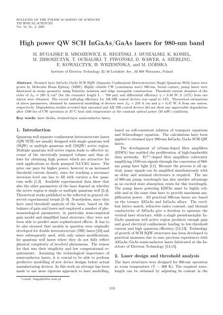
<strong>High</strong> <strong>power</strong> <strong>QW</strong> <strong>SCH</strong> <strong>In<strong>GaAs</strong></strong>/<strong>GaAs</strong> <strong>lasers</strong> <strong>for</strong> <strong>980</strong>-<strong>nm</strong> <strong>band</strong><br />
M. BUGAJSKI ∗ , B. MROZIEWICZ, K. REGIŃSKI, J. MUSZALSKI, K. KOSIEL,<br />
M. ZBROSZCZYK, T. OCHALSKI, T. PIWOŃSKI, D. WAWER, A. SZERLING,<br />
E. KOWALCZYK, H. WRZESIŃSKA, and M. GÓRSKA<br />
Institute of Electron Technology 32/46 Lotników Ave., 02 668 Warszawa, Poland<br />
Abstract. Strained layer <strong>In<strong>GaAs</strong></strong>/<strong>GaAs</strong> <strong>SCH</strong> S<strong>QW</strong> (Separate Confinement Heterostructure Single Quantum Well) <strong>lasers</strong> were<br />
grown by Molecular Beam Epitaxy (MBE). <strong>High</strong>ly reliable CW (continuous wave) <strong>980</strong>-<strong>nm</strong>, broad contact, pump <strong>lasers</strong> were<br />
fabricated in stripe geometry using Schottky isolation and ridge waveguide construction. Threshold current densities of the<br />
order of Jth ≈ 280 A/cm 2 (<strong>for</strong> the resonator length L = 700 µm) and differential efficiency η = 0.40 W/A (41%) from one<br />
mirror were obtained. The record wall-plug efficiency <strong>for</strong> AR/HR coated devices was equal to 54%. Theoretical estimations<br />
of above parameters, obtained by numerical modelling of devices were Jth = 210 A/cm and η = 0.47 W/A from one mirror,<br />
respectively. Degradation studies revealed that uncoated and AR/HR coated devices did not show any appreciable degradation<br />
after 1500 hrs of CW operation at 35 ◦ C heat sink temperature at the constant optical <strong>power</strong> (50 mW) conditions.<br />
Key words: laser diodes, strained-layer semiconductor <strong>lasers</strong>.<br />
1. Introduction<br />
Quantum well separate confinement heterostructure <strong>lasers</strong><br />
(<strong>QW</strong> <strong>SCH</strong>) are usually designed with single quantum well<br />
(S<strong>QW</strong>) or multiple quantum well (M<strong>QW</strong>) active region.<br />
Multiple quantum well active region leads to effective increase<br />
of the electrically pumped volume and thus allows<br />
<strong>for</strong> obtaining high <strong>power</strong>s which are attractive <strong>for</strong><br />
such applications as diode pumped Nd:YAG <strong>lasers</strong>. The<br />
price one pays <strong>for</strong> higher <strong>power</strong>, however is an increased<br />
threshold current density, since <strong>for</strong> reaching a necessary<br />
inversion level one has to fill with carriers a few quantum<br />
wells [1,2]. Available experimental data show that<br />
also the other parameters of the laser depend on whether<br />
the active region is single or multiple quantum well [3,4].<br />
Theoretical works published so far reflected in general observed<br />
experimental trends [5–9]. Nonetheless, since they<br />
have used threshold analysis of the laser, based on the<br />
balance of gain and losses and employed a number of phenomenological<br />
parameters, in particular semi-empirical<br />
gain model and simplified <strong>band</strong> structure, they were not<br />
been able to predict more sophisticated effects. It has to<br />
be also stressed that models in question were originally<br />
developed <strong>for</strong> double heterostructure (DH) <strong>lasers</strong> [10] and<br />
were subsequently used, with only minor modifications,<br />
<strong>for</strong> quantum well <strong>lasers</strong> where they do not fully reflect<br />
physical complexity of involved phenomena. The reason<br />
<strong>for</strong> that was their simplicity and low computational requirements.<br />
Assuming the technological importance of<br />
semiconductor <strong>lasers</strong>, it is crucial to be able to per<strong>for</strong>m<br />
predictive modelling of new device designs be<strong>for</strong>e actual<br />
manufacturing devices. In this work an attempt has been<br />
made to use more rigorous approach to laser modelling,<br />
∗ e-mail: bugajski@ite.waw.pl<br />
113<br />
based on self-consistent solution of transport equations<br />
and Schroedinger equation. The calculations have been<br />
applied to strained layer <strong>980</strong>-<strong>nm</strong> <strong>In<strong>GaAs</strong></strong>/<strong>GaAs</strong> <strong>SCH</strong> <strong>QW</strong><br />
<strong>lasers</strong>.<br />
The development of erbium-doped fiber amplifiers<br />
(EDFA) has enabled the proliferation of high-<strong>band</strong>width<br />
data networks. Er 3+ -doped fiber amplifiers coherently<br />
amplifying 1550-<strong>nm</strong> signals through the conversion of <strong>980</strong><strong>nm</strong><br />
pump laser light [11]. Because the process is all optical,<br />
many signals can be amplified simultaneously with<br />
no delay and minimal electronics is required. The use<br />
of <strong>980</strong>-<strong>nm</strong> pump wavelength has also another advantage<br />
as no excited state absorption exists <strong>for</strong> this wavelength.<br />
The pump <strong>lasers</strong> <strong>power</strong>ing EDFAs must be highly reliable<br />
and at the same time have to provide maximum amplification<br />
<strong>power</strong>. All practical <strong>980</strong>-<strong>nm</strong> <strong>lasers</strong> are based<br />
on the ternary Al<strong>GaAs</strong> and <strong>In<strong>GaAs</strong></strong> alloys. The excellent<br />
lattice match, refractive index contrast, and thermal<br />
conductivity of Al<strong>GaAs</strong> give a freedom to optimize the<br />
vertical laser structure, while a single pseudomorphic In-<br />
<strong>GaAs</strong> quantum well active region produces enough gain<br />
and good electrical confinement leading to low-threshold<br />
current and high quantum efficiency [12,13]. Technology<br />
of growth of <strong>SCH</strong> S<strong>QW</strong> structures has been developed to<br />
practical measures due to ours previous experiences with<br />
Al<strong>GaAs</strong>/<strong>GaAs</strong> semiconductor <strong>lasers</strong> fabricated at the Institute<br />
of Electron Technology [14,15].<br />
2. Laser design and threshold analysis<br />
The laser structures were designed <strong>for</strong> <strong>980</strong>-<strong>nm</strong> operation<br />
at room temperature (T = 300 K). The required wavelength<br />
can be obtained by adjusting In content in the
active layer and the thickness of the quantum well. Assuming<br />
∼ 20% In content in <strong>In<strong>GaAs</strong></strong> <strong>QW</strong>, the thickness<br />
of the quantum well has been estimated roughly to be in<br />
the range between 60 Å and 100 Å to give the emission<br />
in the <strong>980</strong>-<strong>nm</strong> range. This has been generally verified by<br />
PL measurements on the grown test structures. The laser<br />
simulation has been per<strong>for</strong>med using commercial PICS 3D<br />
software package [16]. Typically, besides emission spectra,<br />
P-I (optical <strong>power</strong>-current) characteristics <strong>for</strong> <strong>lasers</strong> with<br />
stripe contact and different resonator lengths are calculated.<br />
The calculated threshold current densities have to<br />
be understood as a bottom limit; in actual devices one<br />
should expect the higher values, due to unavoidable technological<br />
and processing faults and inaccuracies. Numerical<br />
simulation gives us guidelines <strong>for</strong> designing <strong>lasers</strong> and<br />
optimizing their per<strong>for</strong>mance and speeds up development<br />
of practical devices. Since laser per<strong>for</strong>mance optimization<br />
has to be subjected to numerous restrictions (material and<br />
technological), the numerical modelling is an indispensable<br />
tool saving many ef<strong>for</strong>ts which would be otherwise<br />
spent on technological experiments.<br />
2.1. Physical basis of laser symulator. Basic equations<br />
describing operation of semiconductor laser are Poisson’s<br />
equations:<br />
<br />
εε0<br />
− ∇<br />
e ∇V<br />
<br />
=<br />
− n + p + ND (1 − fD) − NAfA + <br />
Ntj (δj − ftj)(1)<br />
and continuity equations <strong>for</strong> electrons and holes<br />
∇Jn − <br />
j<br />
∇Jp + <br />
j<br />
R tj<br />
n − Rsp − Rst − Rau = ∂n ∂fD<br />
+ ND<br />
∂t ∂t<br />
R tj<br />
p + Rsp + Rst + Rau = − ∂n ∂fA<br />
+ NA<br />
∂t ∂t<br />
The above equations govern electrical characteristics of<br />
the device (e.g., I–V characteristics). Analysis of the optical<br />
characteristics requires the solution of Helmholtz equation,<br />
describing optical field distribution in the resonator.<br />
∇ 2 W + k 2 2<br />
0 ε − β W = 0 (4)<br />
j<br />
M. Bugajski et al.<br />
(2)<br />
(3)<br />
The densities of electron and hole currents Jn and Jp can<br />
be expressed as a function of free carrier concentrations<br />
and variations of respective quasi-Fermi levels.<br />
Jn = nµn∇Efn<br />
Jp = pµp∇Efp<br />
(5)<br />
(6)<br />
Laser simulator solves self-consistently the above set of<br />
partial differential equations <strong>for</strong> electrostatic potential V ,<br />
electron and hole concentration n and p, optical field distribution<br />
W and photons number in the resonator S. For<br />
the analysis of semiconductor laser it is important to evaluate<br />
the carrier density and the optical gain of a quantum<br />
well. The standard approach to the modelling is based on<br />
the parabolic <strong>band</strong> model. It is the most efficient model<br />
and usually it reproduces the general trends with satisfactory<br />
accuracy. For more accurate calculations, especially<br />
in the case of strained layer <strong>In<strong>GaAs</strong></strong>/<strong>GaAs</strong> <strong>lasers</strong><br />
one has to relay on more elaborate models. Inclusion of<br />
the biaxial strain in the design of quantum well semiconductor<br />
<strong>lasers</strong> provides an additional degree of freedom<br />
and produces some desirable effects, such as lower<br />
threshold current. The effects of strain are described theoretically<br />
using k p description of the <strong>band</strong> structure in<br />
the quantum well. This type of calculation up to now<br />
has limited capability in analyzing practical design issues<br />
and optimization of laser geometry. The approximate<br />
treatment of the strain is based on the approximation of<br />
non-parabolic <strong>band</strong> structure by an anisotropic parabolic<br />
one (with proper inclusion of strain-induced shifts and<br />
splitting of light hole (LH) and heavy hole (HH) <strong>band</strong>s).<br />
The calculations are based on analytical approximation to<br />
the <strong>band</strong> structure of strained quantum well, which has<br />
been developed recently [17] using an efficient decoupling<br />
method to transfer the 4×4 valence <strong>band</strong> Hamiltonian<br />
into two blocks of 2×2 upper and lower Hamiltonians. As<br />
a result of the decoupling, analytical expressions <strong>for</strong> in<br />
plane valence sub-<strong>band</strong>s dispersion relations can be derived.<br />
Once the parabolic sub<strong>band</strong>s are found, one can<br />
apply conventional approaches to treat carrier concentration<br />
and the optical transition probabilities. The effective<br />
mass perpendicular to the quantum well plane determines<br />
the quantum sub-<strong>band</strong> energies at k = 0, while the densities<br />
of states <strong>for</strong> each sub-<strong>band</strong> are determined using the<br />
in plane effective masses. In the framework of the model<br />
developed in [17] it is also possible to account <strong>for</strong> anticrossing<br />
behaviour of the valence <strong>band</strong> sub-<strong>band</strong>s (i.e.,<br />
valence <strong>band</strong> mixing).<br />
With no carrier injection the active layer material is<br />
strongly absorbing. With carrier injection we can invert<br />
the carrier population near the <strong>band</strong> edge and convert absorption<br />
into gain. The region of positive gain exists in<br />
limited energy range above the <strong>band</strong>gap of the material.<br />
It extends between the <strong>band</strong>gap and the quasi-Fermi level<br />
separation: Eg < hν < △Eg The spectral shape of the<br />
<strong>QW</strong> gain and peak gain on injected carrier density expressions<br />
differ considerably from that of bulk material. These<br />
differences are the consequences of the step-like density of<br />
states in <strong>QW</strong> material. Apart from this, the derivation<br />
of appropriate expression <strong>for</strong> gain follows usual treatment.<br />
The optical gain is calculated using standard perturbation<br />
theory (Fermi’s Golden Rule). The spectrally dependent<br />
gain coefficient can be written in the <strong>for</strong>m,<br />
g(E) =<br />
q2 |M| 2<br />
Eε0m2 ×<br />
cℏNLz<br />
<br />
mr,ijCijAij [fc − (1 − fv)] H (E − Eij)(7)<br />
i,j<br />
where: |M| 2 – bulk momentum transition matrix element;<br />
Cij – spatial overlap factor between states i and j; Aij –<br />
anisotropy (polarization) factor <strong>for</strong> transition i, j; mr,ij<br />
– spatially weighted reduced mass <strong>for</strong> transition i, j; Eij<br />
114 Bull. Pol. Ac.: Tech. 53(2) 2005
<strong>High</strong> <strong>power</strong> <strong>QW</strong> <strong>SCH</strong> <strong>In<strong>GaAs</strong></strong>/<strong>GaAs</strong> <strong>lasers</strong> <strong>for</strong> <strong>980</strong>-<strong>nm</strong> <strong>band</strong><br />
– transition energy between states i and j; N – effective<br />
refractive index; H – Heaviside step function; i, j – conduction,<br />
valence (lh, hh) quantum numbers at Γ point.<br />
For the perfectly confined <strong>QW</strong> states ∆n = 0 selection<br />
rule applies. The reduced mass parameter is given by<br />
m −1<br />
r,ij<br />
= m−1<br />
i<br />
+ m−1<br />
j , where mi and mj are weighted (by<br />
wave function confinement factor in <strong>QW</strong>) averages of <strong>QW</strong><br />
and cladding masses.<br />
Momentum conservation restricts the energies of the<br />
initial and final states. The bulk averaged momentum matrix<br />
element between the conduction and valence states is:<br />
|M| 2 = m2 Eg (Eg + △)<br />
6mc (Eg + 2△/3)<br />
The angular anisotropy factor is normalized so that its<br />
angular average (bulk limit) is unity. For the TE transitions,<br />
with the electric field vector in the plane of the<br />
<strong>QW</strong>, its values are: Aij = 3/4 1 + cos2 <br />
θij <strong>for</strong> e-hh transitions<br />
and Aij = 1/4 5 − 3cos2 <br />
θij <strong>for</strong> e-lh transitions.<br />
The <strong>band</strong>s are assumed to be parabolic in first approximation,<br />
thus the occupation density of the i-th (conduction<br />
or valence) <strong>band</strong> is:<br />
<br />
c,ν<br />
Ef − Ec,ν i<br />
ni, pi = 1 + exp<br />
(9)<br />
kT<br />
kT mc,ν i<br />
πℏ2 ln<br />
Lz<br />
(8)<br />
where the quasi-Fermi energies Ef and the quantum levels<br />
Ei are measured positive into respective <strong>band</strong> from<br />
the k = 0 <strong>band</strong> edge. We assume undoped <strong>QW</strong> with<br />
high injection, so the charge neutrality gives the condition<br />
n = plh + phh. The carrier scattering processes are accounted<br />
<strong>for</strong> by introducing appropriate broadening of the<br />
quantum levels. The net effect of this broadening can be<br />
found by convoluting the Lorentzian shape function with<br />
gain distribution (g ′ (E) = g(E)×L(E)). The broadening<br />
significantly reduces the local gain. The discussed relations<br />
allow <strong>for</strong> calculating gain vs. injected carrier density.<br />
The above equations give the material gain of quantum<br />
well in terms of carrier density, which is not directly<br />
measurable. From the point of view of calculating<br />
properties of semiconductor injection laser the relation<br />
between the current and carrier density must be established<br />
by balancing current with total carrier recombination<br />
rate which consists of radiative and non-radiative<br />
components. The radiative component of carrier recombination<br />
is found from spectrally dependent spontaneous<br />
emission rate. The non-radiative contribution to the current<br />
comes mainly from thermal leakage current and from<br />
Auger recombination. The most common method of estimating<br />
Auger recombination is to use experimentally obtained<br />
Auger coefficients in combination with calculated<br />
carrier density (RA = CN 3 ). Theories can predict Auger<br />
rate to within an order of magnitude. In quantum-well<br />
<strong>lasers</strong> carriers can leak into separate confinement waveguiding<br />
layers as well as leaking out of the entire <strong>SCH</strong><br />
waveguide region into the doped cladding layers has to be<br />
considered. Carrier population in the <strong>SCH</strong> region leads to<br />
recombination giving leakage current density of the order<br />
of 50 A/cm 2 per 10 17 cm −3 of carrier density. This shows<br />
the importance of maintaining low carrier density in the<br />
waveguide regions of the laser.<br />
The theory of gain based on Fermi’s Golden Rule considers<br />
each electron in isolation as it interacts with electromagnetic<br />
field, i.e., it is a single-particle theory and<br />
as such it neglects mutual interactions between electrons.<br />
The physical consequences of many-body effects in dense<br />
electron plasma in <strong>QW</strong>s are basically of two types: excitonic<br />
effects and <strong>band</strong>gap renormalization effects. The<br />
first one will result essentially in the changes of the spectral<br />
shape of material gain curves and will be enhanced<br />
in quantum wells comparing to the bulk material. The<br />
second will produce the <strong>band</strong>gap shrinkage due to the<br />
combined exchange and correlation effects. The net effect<br />
of the bangap shrinkage is the noticeable red-shift of<br />
gain spectrum accompanied by its reshaping and enhancement.<br />
This phenomenon is clearly observable in quantum<br />
well <strong>lasers</strong> where the high threshold carrier density shifts<br />
the lasing wavelength beyond the known <strong>band</strong> edge wavelength<br />
of the quantum well. Nevertheless, all practical<br />
laser simulators available now are based on free-carrier<br />
gain model, which is easier to implement numerically. The<br />
full account of many-body laser theory can be found in<br />
the monograph [18].<br />
2.2. Numerical simulation of <strong>SCH</strong> S<strong>QW</strong> <strong>In<strong>GaAs</strong></strong>/<br />
<strong>GaAs</strong> laser. The sketch of the typical device simulated<br />
is shown in Fig.1. The sequence of layers consists of ntype<br />
<strong>GaAs</strong> buffer, the AlxGa1−xAs n-type barrier layer,<br />
undoped active layer and waveguide, the AlxGa1−xAs ptype<br />
barrier layer and p + -type <strong>GaAs</strong> sub-contact layer.<br />
Active layer is composed of InyGa1−yAs quantum well<br />
enclosed by <strong>GaAs</strong> waveguide. The model was tested <strong>for</strong><br />
different values of structure parameters, i.e., thickness of<br />
individual layers, composition and doping. The indium<br />
content in <strong>In<strong>GaAs</strong></strong> <strong>QW</strong> was varied from y = 0.20 to<br />
y = 0.22 and the well thickness from 60 Å to 100 Å.<br />
The Al<strong>GaAs</strong> compositions x = 0.30 and x = 0.70 were<br />
tested. Finally we have studied the influence of the thickness<br />
of <strong>GaAs</strong> waveguide, which had been changed from<br />
0.1 µm on each side of <strong>QW</strong> to 0.3 µm, on the laser<br />
characteristics. The doping of both emitters was kept<br />
on 5×10 17 cm −3 level <strong>for</strong> all simulations. Such complex<br />
Fig. 1. <strong>SCH</strong> S<strong>QW</strong> <strong>In<strong>GaAs</strong></strong>/<strong>GaAs</strong> strained layer laser structure<br />
Bull. Pol. Ac.: Tech. 53(2) 2005 115
program of investigations would be difficult to realize<br />
by relaying exclusively on technological experiments.<br />
Nevertheless, the key numerical results were confronted<br />
with real experiments to verify calculations and provide<br />
solid foundations <strong>for</strong> hypothesis derived from numerical<br />
experiments. Such combined approach proved<br />
to be very successful in developing <strong>980</strong>-<strong>nm</strong> <strong>lasers</strong>.<br />
Typical, calculated P-I (optical <strong>power</strong>-current) characteristics<br />
<strong>for</strong> <strong>lasers</strong> with stripe width W = 100 µm<br />
and resonator length L = 700 µm are shown in Fig. 2.<br />
Threshold current densities <strong>for</strong> modelled <strong>lasers</strong> are equal<br />
to 197 A/cm 2 and 208 A/cm 2 , depending on construction<br />
details, which are in agreement with values obtained<br />
experimentally by Coleman [12] <strong>for</strong> broad area<br />
strained-layer <strong>In<strong>GaAs</strong></strong>/<strong>GaAs</strong> <strong>lasers</strong> of similar geometry<br />
but with higher Al content in the emitters. The majority<br />
of early <strong>lasers</strong> were GRIN S<strong>QW</strong> type, while now<br />
simple <strong>SCH</strong> S<strong>QW</strong> or <strong>SCH</strong> M<strong>QW</strong> <strong>lasers</strong>, as studied in<br />
this work, dominate, which in most cases makes comparison<br />
of calculated results with available experimental data<br />
only approximate – but general trends are reproduced<br />
properly. The calculated threshold current densities have<br />
to be understood as a bottom limit; in actual devices<br />
one should expect the higher values, due to unavoidable<br />
technological and processing faults and inaccuracies.<br />
Fig. 2. Calculated P-I characteristics of <strong>SCH</strong> S<strong>QW</strong> In-<br />
<strong>GaAs</strong>/<strong>GaAs</strong> <strong>lasers</strong><br />
Application of narrower waveguiding layer (∼ 0.1 µm<br />
on each side of the quantum well) decreases threshold current<br />
by about 25% (cf. Fig. 3) but on the other hand<br />
optical <strong>power</strong> density in the resonator increases roughly<br />
3 times. This may lead to a faster degradation of <strong>lasers</strong>,<br />
M. Bugajski et al.<br />
in particular to the lowering of COD (Catastrophic Optical<br />
Damage) threshold level. The heat generated by the<br />
absorption of laser radiation at the mirrors can result in irreversible<br />
damage of the laser. Since our primary concern<br />
was durability of <strong>lasers</strong> the <strong>for</strong>mer design, with broader<br />
waveguide, was chosen although the penalty of slightly<br />
higher threshold had to be paid. Extremely low threshold<br />
current densities, of the order of 120 A/cm 2 , can be obtained<br />
using both narrow waveguide (∼ 0.1 µm) and high<br />
Al content (x = 0.70) in the emitters. Such construction<br />
can be useful <strong>for</strong> low <strong>power</strong>, high-speed <strong>lasers</strong> with narrow<br />
stripes (5 µm–10 µm) operated at low drive currents.<br />
Fig. 3. Calculated P-I characteristics of <strong>SCH</strong> S<strong>QW</strong> In-<br />
<strong>GaAs</strong>/<strong>GaAs</strong> <strong>lasers</strong> with different waveguide thickness<br />
The influence of <strong>QW</strong> thickness, with the other construction<br />
details unchanged, on laser parameters has been<br />
also studied. The results of calculation show that differential<br />
quantum efficiency of the laser (η) grows with decreasing<br />
<strong>QW</strong> thickness, reaching 0.54 W/A (42.7%) <strong>for</strong><br />
L = 60 Å. On the other hand, the threshold current<br />
density J th reaches minimum 121 A/cm 2 <strong>for</strong> L = 80 Å.<br />
The results suggest that a good optimization procedure<br />
would be to choose <strong>QW</strong> thickness L = 80 Å and vary In<br />
content in the active region to get required wavelength<br />
of laser emission, i.e., <strong>980</strong> <strong>nm</strong>. The thickness of both<br />
emitters should be at least 1.0 µm each, preferably 1.5<br />
µm, to assure that optical field of the fundamental mode<br />
does not penetrates the highly absorbing <strong>GaAs</strong> regions.<br />
The final laser structure has been decided according<br />
to the simulation results. The thickness, composition<br />
and doping of individual layers constituting<br />
the structure were chosen as listed in the Table 1.<br />
Tabele 1<br />
Typical parameters of <strong>SCH</strong> S<strong>QW</strong> <strong>In<strong>GaAs</strong></strong>/<strong>GaAs</strong>/Al<strong>GaAs</strong> laser structures<br />
Buf<strong>for</strong> n-emiter Waveguide <strong>QW</strong> Waveguide p-emiter Cap<br />
1 µm <strong>GaAs</strong>:Si 1 µm – 1.5 µm 0.1–0.3 µm 80 Å 0.1–0.3 µm 1 µm – 1.5 µm 0.25 µm<br />
n = 2×10 18 cm −3 AlxGa1−xAs:Si <strong>GaAs</strong> InxGa1−xAs <strong>GaAs</strong> AlxGa1−xAs:Be <strong>GaAs</strong>:Be<br />
0.2 µm x = 0.3 x = 0.20–0.22 x = 0.3<br />
AlxGa1−xAs:Si n = 5×10 17 cm −3<br />
x = 0.0-0.3<br />
n = 5×10 17 cm −3<br />
undoped undoped undoped p = 5×10 17 cm −3<br />
p = 3×10 19 cm −3<br />
116 Bull. Pol. Ac.: Tech. 53(2) 2005
<strong>High</strong> <strong>power</strong> <strong>QW</strong> <strong>SCH</strong> <strong>In<strong>GaAs</strong></strong>/<strong>GaAs</strong> <strong>lasers</strong> <strong>for</strong> <strong>980</strong>-<strong>nm</strong> <strong>band</strong><br />
<strong>SCH</strong> S<strong>QW</strong> laser structures were grown by molecular beam<br />
epitaxy (MBE) in Riber 32P reactor in a manner similar<br />
to previously described [19].<br />
The structures were grown on (100) <strong>GaAs</strong> conductive<br />
substrates. The sequence of layers <strong>for</strong> typical, optimized<br />
<strong>for</strong> reliable high <strong>power</strong> CW operation, structure<br />
consisted of n-type <strong>GaAs</strong> buffer, the Al0.3Ga0.7As n-type<br />
barrier layer, undoped active layer and waveguide, the<br />
Al0.3Ga0.7As p-type barrier layer and p + -type <strong>GaAs</strong> subcontact<br />
layer. Active layer and waveguide comprised of<br />
In0.21Ga0.79As 80 Å quantum well enclosed by 0.3 µm<br />
<strong>GaAs</strong> layers.<br />
3. Strained-layer laser structures – MBE<br />
growth related issues<br />
The growth of <strong>In<strong>GaAs</strong></strong>/<strong>GaAs</strong> heterostructures is much<br />
more difficult than the growth of Al<strong>GaAs</strong>/<strong>GaAs</strong> ones.<br />
The reason <strong>for</strong> that is large lattice mismatch between substrate<br />
and the growing layer. The lattice constant of <strong>GaAs</strong><br />
is equal to 5.6533 Å, whereas that of InAs equals 6.0584 Å,<br />
which results in 7% lattice mismatch between those two<br />
semiconductors and precludes the growth of high indium<br />
containing <strong>In<strong>GaAs</strong></strong> on <strong>GaAs</strong> substrate. The room temperature<br />
<strong>band</strong> gap of InxGa1−xAs ternary alloy varies from<br />
1.424 eV (<strong>GaAs</strong>) to 0.36 eV (InAs). The energy range<br />
close to 1.424 eV is attainable by using InxGa1−xAs layers<br />
grown on <strong>GaAs</strong> substrates. This way the layers with indium<br />
content up to 0.2 and reasonable thickness up to 100<br />
Å can be grown [20]. The layer with different lattice constant<br />
than that of the substrate undergoes a tetragonal<br />
de<strong>for</strong>mation during the growth. Depending on whether<br />
the lattice constant of the layer is greater or smaller than<br />
the lattice constant of the substrate, we have biaxial compressive<br />
or biaxial tensile strain in the plane of the layer<br />
and appropriate de<strong>for</strong>mation of the elementary lattice cell<br />
in perpendicular direction <strong>for</strong> which the strain is relaxed.<br />
With increase of the layer thickness, the elastic de<strong>for</strong>mation<br />
energy stored in the crystal grows and when its value<br />
exceeds certain threshold value determined by the Hook’s<br />
law the stress is released and the misfit dislocations are<br />
<strong>for</strong>med [21]. The thickness of the layer <strong>for</strong> which stress<br />
relaxation occurs is called a critical thickness. It depends<br />
mainly on the lattice mismatch between the layer and the<br />
substrate. For the materials with large lattice mismatch,<br />
such as <strong>In<strong>GaAs</strong></strong> on <strong>GaAs</strong>, the critical thickness values are<br />
few orders of magnitude smaller than that <strong>for</strong> Al<strong>GaAs</strong> on<br />
<strong>GaAs</strong> with a similar composition. The lattice mismatch<br />
is the main factor responsible <strong>for</strong> difficulties encountered<br />
in the growth of <strong>In<strong>GaAs</strong></strong> on <strong>GaAs</strong>. The growth of lattice<br />
mismatched layers can be realized only in the limited<br />
range of thickness and compositions and even then is a<br />
difficult task, requiring a precise knowledge of the phenomena<br />
occurring in strained materials.<br />
Band structure of III–V semiconductor compounds<br />
changes appreciably under biaxial strain originating in<br />
thin layers of these materials grown on lattice mismatched<br />
substrates. The presence of strain removes degeneracy of<br />
valence <strong>band</strong> k = 0, changes <strong>band</strong> gap as well as dispersion<br />
relation in the valence <strong>band</strong>. In quantum wells<br />
the influence of strain is even more complicated. All<br />
these changes can be positively exploited in designing<br />
quantum well <strong>lasers</strong>, resulting in improved device characteristics<br />
and flexibility in fabricated <strong>lasers</strong> parameters<br />
[22]. Penalty paid <strong>for</strong> this is difficult growth technology.<br />
Quality of interfaces and defects in strained layer semiconductor<br />
structures greatly affect parameters of <strong>lasers</strong>.<br />
Roughness of surfaces is cause of dissipative loss of emission<br />
and probable non-radiative recombination on defects<br />
involved. Because of that total internal losses increase<br />
which leads to higher threshold current and decrease of<br />
quantum efficiency of the <strong>lasers</strong>. This finally causes decrease<br />
of external differential efficiency (slope of optical<br />
<strong>power</strong> vs. current characteristics is smaller). To achieve<br />
as smooth as possible and defect free interfaces (in particular<br />
the most important are interfaces between quantum<br />
well and waveguide) we have applied photoluminescence<br />
measurements per<strong>for</strong>med on as grown structures [23].<br />
The per<strong>for</strong>mance and reliability of semiconductor<br />
<strong>lasers</strong> depends critically on the crystal growth technique.<br />
In this respect, <strong>lasers</strong> are probably the most demanding<br />
III–V minority carrier devices. Fabrication of high quality<br />
laser structures by MBE needs a careful optimization<br />
of the growth conditions. From the point of view of MBE<br />
technology several factors are of great importance: high<br />
purity and structure perfection of undoped layers, the relevant<br />
profiles of dopant concentration, good quality of interfaces,<br />
high dopant concentration in contact layers, etc.<br />
There<strong>for</strong>e, the optimization of the MBE process comprises<br />
the determination of the growth conditions <strong>for</strong> each layer<br />
of the laser structure. The growth must proceed with<br />
right combination of temperatures of substrate and ratios<br />
of group V/III atomic beams, which guarantee appropriate<br />
reconstruction of surface and proper growth conditions<br />
<strong>for</strong> each layer, which indeed vary appreciably. This<br />
allows us to achieve layers of the best optical quality.<br />
In general Al<strong>GaAs</strong> should be grown at as high temperatures<br />
as possible and at low V/III ratio (to minimize<br />
oxygen content in the layers), whereas <strong>In<strong>GaAs</strong></strong> prefers<br />
substantially lower temperatures and higher V/III beam<br />
ratios. Fulfilling these conditions requires abrupt changes<br />
of beam fluxes which is difficult to realize due to thermal<br />
inertia of effusion cells. To avoid process interruptions at<br />
the surfaces we have used two arsenic cells preheated at<br />
different temperatures. To monitor the state of the crystal<br />
surface at any stage of the growth process the RHEED<br />
(Reflection <strong>High</strong> Energy Electron Diffraction) system was<br />
used. The RHEED patterns were registered by CCD camera<br />
and then processed in real time and recorded by a<br />
computer acquisition system. The system enabled us to<br />
register RHEED intensity oscillations and, as a result, to<br />
determine the growth rate. As a result, we had at our disposal<br />
two independent methods of measuring the growth<br />
rate. The first one based on the measurement of atomic<br />
Bull. Pol. Ac.: Tech. 53(2) 2005 117
M. Bugajski et al.<br />
Table 2<br />
Optimized MBE growth conditions <strong>for</strong> <strong>In<strong>GaAs</strong></strong>/<strong>GaAs</strong> laser structures<br />
Material Layer T ( ◦ C) Growth rate (µm/hr) V/III flux ratio Reconstruction<br />
<strong>GaAs</strong> buffer 580 0.8 4–5 (2×4)<br />
waveguide 550–580<br />
subcontact 540 (3×1)<br />
Al0.30Ga0.70As emitters 690 1.15 2.1 (3×1)<br />
In0.20Ga0.80As <strong>QW</strong> 550 1.0 4 (2×4)<br />
fluxes and the second one based on registering the<br />
RHEED intensity oscillations. That additional possibility<br />
strengthened our control over growth process and<br />
turned out to be crucial in developing the technology of<br />
laser structures. The analysis of RHEED diffraction patterns<br />
allowed us to determine substrate reconstruction <strong>for</strong><br />
the case of growth of different materials composing laser<br />
structure, depending on the temperature and respective<br />
beam fluxes. It is well known that the quality of layers<br />
and their usefulness <strong>for</strong> certain applications can be linked<br />
to the type of surface reconstruction during the growth.<br />
For <strong>GaAs</strong> there are known types of reconstruction which<br />
produce layers especially suitable <strong>for</strong> optical applications.<br />
In the case of <strong>In<strong>GaAs</strong></strong> the subject is less studied but the<br />
general trends are similar. Based on our previous experiences<br />
with <strong>GaAs</strong>/Al<strong>GaAs</strong> system and research done <strong>for</strong><br />
this work we have found the set of optimum growth conditions<br />
(in terms of beam fluxes, surface reconstruction and<br />
temperatures) <strong>for</strong> the growth of <strong>In<strong>GaAs</strong></strong>/<strong>GaAs</strong>/Al<strong>GaAs</strong><br />
strained layer structures. They are listed in Table 2.<br />
Optimized MBE growth parameters allowed <strong>for</strong> the<br />
growth of defect free laser structures in the whole range<br />
of indium content in the active region studied (0.10–0.25<br />
mole fraction of In). Quality of the structures was routinely<br />
studied by PL (photoluminescence), PR (photoreflectance)<br />
and occasionally by TEM.<br />
4. Device fabrication and laser<br />
characteristics<br />
The broad contact (100 µm stripe width) ridge-waveguide<br />
<strong>lasers</strong> were fabricated from <strong>SCH</strong> S<strong>QW</strong> structures following<br />
a standard processing procedures used previously <strong>for</strong><br />
DH Al<strong>GaAs</strong>/<strong>GaAs</strong> <strong>lasers</strong>. The AuGeNi/Au contact with<br />
additional thick Au layer was used <strong>for</strong> n-side of the device.<br />
The p-contact comprised of the following sequence<br />
of layers: Cr (50 <strong>nm</strong>), Pt (200 <strong>nm</strong>), Cr (50 <strong>nm</strong>) and Pt<br />
(150 <strong>nm</strong>). The individual <strong>lasers</strong> were In-soldered, p-side<br />
down, on copper blocks and contacted by a gold wire.<br />
The p-side down soldering of <strong>lasers</strong> has an advantage over<br />
n-side down mounting manifesting in better heat sinking,<br />
although it is much more difficult technologically and generally<br />
results in lower yield. The laser chip and the structure<br />
soldered to copper heat sink are shown in Fig. 4a<br />
and 4b, respectively. All laser chips were tested be<strong>for</strong>e<br />
soldering, using needle probe and micromanipulator. The<br />
P-I characteristics and spectral characteristics were measured.<br />
The CCD camera was used to observe near-field<br />
picture of laser emission. Light from the laser was delivered<br />
to the spectrometer using optical fiber. The measurements<br />
of laser characteristics, data acquisition and data<br />
processing were controlled by PC computer. For selected<br />
devices angular distribution of laser emission in two perpendicular<br />
directions (far-field pattern) was also recorded.<br />
Finally, devices were encapsulated in metal cases with<br />
window. Some of the <strong>lasers</strong> had antireflection (AR) and<br />
high-reflectivity (HR) coatings deposited on the front and<br />
rear facets respectively. One layer of SiO2 was used <strong>for</strong> AR<br />
coating and Si/SiO2 multilayer was used <strong>for</strong> HR-coating.<br />
The AR, HR coatings were deposited on lines of <strong>lasers</strong>,<br />
be<strong>for</strong>e dividing them into individual chips.<br />
Fig. 4. The laser chip (a) and the structure soldered to copper<br />
heat sink (b)<br />
The preliminary results of works on <strong>980</strong>-<strong>nm</strong> <strong>lasers</strong> have<br />
been published in series of recent papers of the authors<br />
[24–26]. Here we report updated results on degradation<br />
studies and selected best characteristics of the <strong>lasers</strong>. Fabricated<br />
<strong>lasers</strong> exhibited similar characteristics to the other<br />
structures of this type published in the literature [27–<br />
31]. Threshold current densities of the order of Jth ≈ 280<br />
A/cm 2 (<strong>for</strong> the resonator length L = 700 µm) and differential<br />
quantum efficiency η = 0.40 W/A (41%) were<br />
obtained. The wall-plug efficiency of the <strong>lasers</strong> without<br />
AR coating reached 38%. The optical <strong>power</strong>-current<br />
characteristics (P-I) <strong>for</strong> <strong>lasers</strong> fabricated from the same<br />
wafer showed almost equal thresholds and slightly different<br />
differential efficiencies. The linearity of the characteristics<br />
was good; there was no kinks and thermal rollover<br />
<strong>for</strong> highest <strong>power</strong>s observed. The characteristics were<br />
typically recorded <strong>for</strong> pulse operation with filling factor<br />
ff = 0.1% (pulse length 200 ns, repetition 5 kHz).<br />
Theoretical estimation of threshold current density<br />
and differential efficiency obtained by numerical modelling<br />
of the devices were Jth ≈ 210 A/cm 2 and η = 0.47<br />
118 Bull. Pol. Ac.: Tech. 53(2) 2005
<strong>High</strong> <strong>power</strong> <strong>QW</strong> <strong>SCH</strong> <strong>In<strong>GaAs</strong></strong>/<strong>GaAs</strong> <strong>lasers</strong> <strong>for</strong> <strong>980</strong>-<strong>nm</strong> <strong>band</strong><br />
W/A, respectively. The obtained experimentally threshold<br />
currents are fully acceptable, whereas differential efficiency<br />
could have been still improved. They lower than<br />
theoretically predicted value is most probably caused absorption<br />
losses in the cavity. Further work aimed on lowering<br />
absorption losses is required. The <strong>lasers</strong> generated<br />
at <strong>980</strong> <strong>nm</strong> – 990 <strong>nm</strong> wavelength range, depending on the<br />
part of the wafer from which they have been made, with<br />
the half-width of the emission <strong>band</strong> of the order of 1<br />
<strong>nm</strong>, just above the threshold and up to 3 <strong>nm</strong> at high<br />
currents (high optical <strong>power</strong>). Emission spectrum contained<br />
many well-distinguished longitudinal modes, belonging<br />
to the fundamental transverse and lateral modes.<br />
As it has been mentioned earlier the requirement of precise<br />
wavelength control demanded by application of the<br />
devices as a pump source <strong>for</strong> Er 3+ -doped amplifiers is difficult<br />
to fulfil but manageable. Besides the variation of<br />
the wavelength over the wafer, there are global variations<br />
between different MBE runs. Usually, the best reproducibility<br />
is achieved when one grows a series of 2” wafers<br />
with laser structures, without interruption <strong>for</strong> other processes.<br />
That assures a maximum stability of growth parameters.<br />
Fig. 5. Comparison of P-I characteristics of <strong>lasers</strong> with or<br />
without AR/HR coatings<br />
To <strong>for</strong>ce laser emission through one, selected mirror<br />
one has to apply AR/HR coating. The other benefits<br />
of dielectric passivation of the mirrors is theoretically<br />
doubled differential efficiency of the laser and higher<br />
resistivity to degradation. The last particularly refers<br />
to increased COD level and greatly enhanced durability.<br />
According to recent reports [32], strained-layer In-<br />
<strong>GaAs</strong>/<strong>GaAs</strong> <strong>lasers</strong> without mirror coating lived in CW<br />
regime on average about 250 hrs, whereas the lifetime<br />
of those with AR/HR coatings reached 5000–10000 hrs.<br />
Typical light-current characteristics of the <strong>lasers</strong> without<br />
AR/HR coatings and with AR/HR coatings, from one lot,<br />
are compared in Fig. 5. The threshold current of <strong>lasers</strong><br />
with AR/HR coatings was unchanged comparing to uncoated<br />
ones but we have observed roughly twice increase<br />
in differential quantum efficiency. The record wall-plug<br />
efficiency <strong>for</strong> AR/HR coated devices was equal to 54%.<br />
Which is among the best values obtained <strong>for</strong> that type of<br />
<strong>lasers</strong>.<br />
For some <strong>lasers</strong> we have per<strong>for</strong>med aging tests. The<br />
<strong>lasers</strong> <strong>for</strong> the tests were selected on the basis of initial<br />
screening based on threshold current determination. Only<br />
the <strong>lasers</strong> with threshold within the limit of up to twice<br />
the average threshold have been subjected to lifetime testing.<br />
No special ef<strong>for</strong>t was made to select particularly good<br />
devices, rather we tried to chose a spectrum of different<br />
initial quality devices. Fabricated <strong>lasers</strong> showed in general<br />
good reliability. The uncoated devices, did not show an<br />
appreciable degradation after over 1000 hrs of CW operation<br />
at 35 ◦ C heat sink temperature, with 50 mW emitted<br />
<strong>power</strong> (in a constant <strong>power</strong> mode). This result can be extrapolated<br />
to 10 6 hrs of pulse operation with ff = 0.1%.<br />
In the light of the results published in literature [32] this<br />
is extremely good result, even having in mind that the<br />
<strong>lasers</strong> with whom we compare our results were operated<br />
at 100 mW optical <strong>power</strong>. A total of 10 devices were<br />
placed on life test. The <strong>lasers</strong> with coated mirrors are<br />
at the moment of writing this paper still operated at the<br />
aging frame and their CW working time reaches 1500 hrs.<br />
Only one of them failed during the test and the rest maintan<br />
basicaly unchanged current. This is to be compared<br />
with typical CW operating times of a few khrs, published<br />
in the literature [33–35]. The apparent immunity of investigated<br />
<strong>lasers</strong> to sudden failure is striking and despite<br />
the small statistical base it is undoubtedly an inherent<br />
property of strained-layer <strong>In<strong>GaAs</strong></strong>/<strong>GaAs</strong> <strong>lasers</strong> as compared<br />
to conventional Al<strong>GaAs</strong>/<strong>GaAs</strong> <strong>lasers</strong>. Summarizing<br />
the results of aging test per<strong>for</strong>med so far and those,<br />
which are in progress, we may conclude that they are in<br />
agreement with the similar studies <strong>for</strong> the state-of-the-art,<br />
<strong>In<strong>GaAs</strong></strong>/<strong>GaAs</strong> <strong>lasers</strong>.<br />
5. Thermal properties of <strong>lasers</strong><br />
The temperature at the facet has a critical role in device<br />
reliability and per<strong>for</strong>mance. Catastrophic optical damage<br />
(COD) failure of a laser device occurs at the facet and is<br />
caused by absorption of light at the facet which leads to<br />
a local <strong>band</strong>-gap reduction with consequent increased absorption<br />
and temperature rise. The runaway effect leads<br />
to device failure. Thus the local facet temperature is indicative<br />
of these processes. In addition the lateral temperature<br />
profile creates a refractive index profile which<br />
has a strong effect on device per<strong>for</strong>mance. The lateral<br />
refractive index profile induced by a non-uni<strong>for</strong>m junction<br />
heating plays a dominant role in determining lateral<br />
modes and emission characteristics of broad-area <strong>lasers</strong><br />
during continuous (CW) and long-pulse operation. This<br />
is due to thermal focusing caused by temperature induced<br />
lateral index profile. Understanding and characterizing<br />
these thermal effects is important to development of high<br />
<strong>power</strong> CW <strong>lasers</strong>. We have developed an in-situ measurement<br />
technique <strong>for</strong> spatially resolved facet temperature<br />
Bull. Pol. Ac.: Tech. 53(2) 2005 119
measurements. The method allows <strong>for</strong> facet temperature<br />
mapping under differing operating conditions and assessment<br />
of degradation of facets caused by high densities<br />
of optical field in the resonator. The measurements also<br />
qualify the bonding quality and optimum choice of submount<br />
material <strong>for</strong> heat removal.<br />
5.1. Temperature mapping system. Figure 6 shows<br />
the experimental set-up developed <strong>for</strong> the thermoreflectance<br />
measurements of facet heating in semiconductor<br />
<strong>lasers</strong>. The temperature induced changes of the probe<br />
beam reflectivity are generally small (∼ 10 −5 K −1 ) and<br />
dependent on the probe beam wavelength. We limit ourselves<br />
to single wavelength measurements and per<strong>for</strong>m<br />
mapping of the temperature distribution, using calibration<br />
described in the subsequent section.<br />
Fig. 6. The experimental set-up <strong>for</strong> thermoreflectance measurements<br />
of facet heating in semiconductor <strong>lasers</strong><br />
The dimensions that are of interest are the active region<br />
(typically 1 µm high by 50–200 µm wide) and the<br />
surrounding regions through which the heat is dissipated.<br />
This will amount to several 10 s of microns in the height<br />
direction. The spatial resolution of the system is determined<br />
by: (1) probe beam focusing and (2) positioning<br />
accuracy of translation stages. The probe beam can be focused,<br />
using special techniques, down to single micron diameter.<br />
The piezoelectric transducers allow 300×300 µm 2<br />
M. Bugajski et al.<br />
scanning range with 0.2 µm positioning accuracy. The<br />
vertical positioning is also done by piezoelectric transducer.<br />
The positioning of the laser facet in the focal plane<br />
of the optical system is crucial <strong>for</strong> focusing. The probing<br />
beam focusing on the sample is done with reflecting microscope<br />
objective. Because of its all reflecting construction<br />
it is free from chromatic aberration. The objective consists<br />
of a small convex primary mirror and a larger concave<br />
secondary mirror. The experiments showed that reflecting<br />
objective has clear advantages over refracting objectives<br />
of equivalent aperture and focal length. The software <strong>for</strong><br />
the controlling x-y-z microstages movement and data acquisition<br />
uses Lab View plat<strong>for</strong>m. The movement of the<br />
piezoelectric stages is controlled by IEEE interface.<br />
The thermoreflectance mapping system has been<br />
tested <strong>for</strong> various modes of operation. It can be used<br />
<strong>for</strong> simple reflectance (R) measurements, relative (differential)<br />
reflectance measurements (∆R/R <strong>for</strong> given wavelength<br />
λ and spectral thermoreflectance measurements.<br />
The relative variation of reflectance (∆R/R is linear versus<br />
the temperature variation ∆T :<br />
∆R/R = k∆T, (1/k = CT R) (10)<br />
with CT R being thermoreflectance coefficient. An accurate<br />
calibration method is an essential element of any<br />
quantitative thermometry techniques. This is of particular<br />
importance <strong>for</strong> the thermoreflectance studies of semiconductor<br />
<strong>lasers</strong>, whose constituent materials have optical<br />
properties that are not well-characterized or can vary depending<br />
on the processing details. Very few data exist<br />
<strong>for</strong> the absolute values of CT R (thermoreflectance coefficient)<br />
in the literature. Reported values on facet temperature<br />
scatter in the wide range under high <strong>power</strong> operation,<br />
although each measurement technique is based on<br />
the temperature dependence of inherent material parameters,<br />
such as refractive index and energy gap. There<strong>for</strong>e,<br />
the absolute facet temperatures reported are difficult<br />
to compare. Due to the fact that the coefficient CT R<br />
depends both on probed material, and the experimental<br />
conditions, it should not be taken from the literature, but<br />
rather determined in-situ, on the probed sample itself.<br />
The value of the thermoreflectance constant <strong>for</strong> the probe<br />
beam wavelength (λ = 632.8 <strong>nm</strong>, used in this work equals<br />
8×10 3 K.<br />
The example of temperature distribution maps <strong>for</strong> different<br />
supply currents, <strong>for</strong> the laser mounted p-side down<br />
on SiC submount and subsequently on the copper heat<br />
sink is shown in Fig. 7. The temperature increase is<br />
negligible, even at very high emitted <strong>power</strong>s, under CW<br />
operation. This is because of the quality of the structure<br />
and very efficient heat removal. However, <strong>for</strong> not<br />
optimized devices the temperature increase on the mirror<br />
can easily exceed 100 K, which may eventually result in<br />
serious damage of the mirror and the whole laser.<br />
120 Bull. Pol. Ac.: Tech. 53(2) 2005
<strong>High</strong> <strong>power</strong> <strong>QW</strong> <strong>SCH</strong> <strong>In<strong>GaAs</strong></strong>/<strong>GaAs</strong> <strong>lasers</strong> <strong>for</strong> <strong>980</strong>-<strong>nm</strong> <strong>band</strong><br />
Fig. 7. The temperature distribution maps <strong>for</strong> different supply currents, <strong>for</strong> the laser mounted p-side down<br />
6. Conclusions<br />
We have developed MBE technology of strained layer<br />
CW <strong>In<strong>GaAs</strong></strong>/<strong>GaAs</strong> <strong>SCH</strong> S<strong>QW</strong> <strong>lasers</strong> operating at <strong>980</strong><strong>nm</strong><br />
<strong>band</strong>. Broad contact, pump <strong>lasers</strong> were fabricated in<br />
stripe geometry using Schottky isolation and ridge waveguide<br />
construction. Threshold current densities of the order<br />
of Jth ≈ 280 A/cm 2 and differential quantum efficiency<br />
η = 0.40 W/A (41%) from one mirror were obtained.<br />
The wall-plug efficiency of the uncoated <strong>lasers</strong> was<br />
38%. The record wall-plug efficiency <strong>for</strong> AR/HR coated<br />
devices was equal to 54%. Theoretical estimation of above<br />
mentioned quantities were Jth = 280 A/cm 2 and η = 0.47<br />
W/A respectively. Degradation studies revealed that uncoated<br />
devices did not show any appreciable degradation<br />
after 1000 hrs of CW operation with 50 mW of emitted<br />
<strong>power</strong>. Similar life tests, with positive results, are ongoing<br />
<strong>for</strong> AR/HR coated devices already <strong>for</strong> 1500 hrs at the<br />
time of writing this paper. These results are acceptable<br />
even considering such demanding applications as pump<br />
source <strong>for</strong> EDFAs. There is however a need <strong>for</strong> more systematic<br />
measurements in CW condition <strong>for</strong> both, structures<br />
with and without coatings, as it is necessary to have<br />
better statistics of fabricated <strong>lasers</strong> reliability. We have<br />
also developed new technique to monitor the laser facets<br />
heating in real time and to correlate these measurements<br />
with device per<strong>for</strong>mance and reliability. The method is<br />
based on thermoreflectance, which is a modulation technique<br />
relaying on periodic facet temperature modulation<br />
induced by pulsed current supply of the laser. The periodic<br />
temperature change of the laser induces variation<br />
of the refractive index and consequently modulates probe<br />
beam reflectivity. The technique has a spatial resolution<br />
of about ∼ 1 µ and temperature differences of a degree<br />
can be measured. It can be applied to any kind of edge<br />
emitting <strong>lasers</strong> or laser bars.<br />
Acknowledgements. This work has been supported by<br />
KBN grant PBZ -MIN-009/T11/2003.<br />
References<br />
[1] P. Derry and A. Yariv, “Ultralow-threshold graded-index<br />
separate-confinement singlequantum well burried heterostructure<br />
(Al,Ga)As <strong>lasers</strong> with high reflectivity coatings”,<br />
Appl. Phys. Lett. 50, 1773 (1987).<br />
[2] W.T. Tsang, “Extremely low threshold (Al,Ga)As modified<br />
multiquantum well heterostructure <strong>lasers</strong> grown<br />
by molecular beam epitaxy”, Appl. Phys. Lett. 39, 786<br />
(1981).<br />
[3] K. Prosyk, J.G. Simmons and J.D. Evans, “Well number,<br />
length, and temperature dependence of efficiency and<br />
loss in <strong>In<strong>GaAs</strong></strong>P-InP compressively strained M<strong>QW</strong> ridge<br />
wavequide <strong>lasers</strong> at 1.3 µm”, IEEE J. Quantum Electron.<br />
QE-33, 1360 (1997).<br />
[4] K. Prosyk, J.G. Simmons and J.D. Evans, “A systematic<br />
empirical study of the well number and length on<br />
the temperature sensitivity of the threshold current in<br />
<strong>In<strong>GaAs</strong></strong>P-InP M<strong>QW</strong> <strong>lasers</strong>”, IEEE J. Quantum Electron.<br />
QE-34, 535 (1998).<br />
[5] P.W.A. Mc Ilroy, A. Kurobe and Y. Uematsu, “Analysis<br />
and application of theoretical gain curves to the design of<br />
multi-quantum well <strong>lasers</strong>”, IEEE J. Quantum Electron.<br />
QE-21, 1958 (1985).<br />
Bull. Pol. Ac.: Tech. 53(2) 2005 121
[6] A. Kurobe, H. Furuyama, S. Naritsuka, N. Sugiyama,<br />
Y. Kokubun and M. Nakamura, “Effects of well number,<br />
cavity length, and facet reflectivity on the reduction of<br />
threshold current of <strong>GaAs</strong>/Al<strong>GaAs</strong> multiquantum well<br />
<strong>lasers</strong>”, IEEE J. Quantum Electron. QE-24, 635 (1988).<br />
[7] J.Z. Wilcox, G.L. Peterson, S. Ou, J.J. Yang, M. Jansen<br />
and D. Schechter, “Gain- and threshold-current dependence<br />
<strong>for</strong> multiple-quantum well <strong>lasers</strong>”, J. Appl. Phys.<br />
64, 6564 (1988).<br />
[8] S.P. Cheng, F. Brillouet and P. Correc, “Design of quantum<br />
well Al<strong>GaAs</strong>-<strong>GaAs</strong> stripe <strong>lasers</strong> <strong>for</strong> minimization of<br />
threshold current-Application to ridge structures”, IEEE<br />
J. Quantum Electron. QE-24, 2433 (1988).<br />
[9] M. Rosenzweig, M. Mohrle, H. Duser and H. Venghaus,<br />
“Threshold-current analysis of <strong>In<strong>GaAs</strong></strong>-<strong>In<strong>GaAs</strong></strong>P<br />
multiquantum well separate-confinement <strong>lasers</strong>”, IEEE J.<br />
Quantum Electron. QE-27, 1804 (1991).<br />
[10] H.C. Casey and Jr., M.B. Panish, Heterostructure Lasers,<br />
Academic Press, New York, 1978.<br />
[11] T. Strite and G. Hoven, “Trends in pump laser diode markets<br />
and technology”, Lightwave 16 (2), 55–62 (1999).<br />
[12] J.J. Coleman, “Strained-layer quantum well heterostructure<br />
<strong>lasers</strong>”, Thin Solid Films 216, 68–71 (1992).<br />
[13] S.D. Offsey, W.J. Schaff, L.F. Lester, L.F. Eastman and<br />
S.K. McKernan, “Strained-layer <strong>In<strong>GaAs</strong></strong>-<strong>GaAs</strong>-Al<strong>GaAs</strong><br />
<strong>lasers</strong> grown by molecular beam epitaxy <strong>for</strong> high speed<br />
modulation”, IEEE J. Quantum Electronics QE-27, 1455–<br />
1462 (1991).<br />
[14] M. Bugajski, M. Kaniewska, K. Regiński, A. Maląg,<br />
S. Łepkowski and J. Muszalski, “GRIN <strong>SCH</strong> S<strong>QW</strong> Al-<br />
<strong>GaAs</strong>/<strong>GaAs</strong> <strong>lasers</strong> grown by molecular beam epitaxy:<br />
Modeling and operating characteristics”, Proc. SPIE<br />
3186, 310 (1997).<br />
[15] M. Bugajski, M. Kaniewska, K. Regiński, J. Muszalski,<br />
D. Kryńska and A. Litkowiec, “GRIN <strong>SCH</strong> S<strong>QW</strong> Al-<br />
<strong>GaAs</strong>/<strong>GaAs</strong> <strong>lasers</strong> grown by molecular beam epitaxy”,<br />
Electron Technology 29, 346–350 (1996).<br />
[16] PICS 3D Instruction Manual, Crosslight Software Inc.,<br />
CA 1998<br />
[17] S.L. Chuang, “Efficient <strong>band</strong>-structure calculation of<br />
strained quantum-wells”, Phys. Rev. B43, 9649–9661<br />
(1991).<br />
[18] W.W. Chow, S.W. Koch and M. Sargent III, Semiconductor<br />
Laser Physics, Springer-Verlag, Berlin Heidelberg,<br />
1994.<br />
[19] K. Regiński and M. Bugajski, “MBE technology of semiconductor<br />
quantum well <strong>lasers</strong>”, Opto-Electron. Rev. 4,<br />
101–116 (1996).<br />
[20] J. Kątcki, J. Ratajczak, J. Adamczewska, F. Phillip, N.Y.<br />
Jin-Phillip, K. Regiński, and M. Bugajski, “Formation of<br />
dislocations in <strong>In<strong>GaAs</strong></strong>/<strong>GaAs</strong> heterostructures”, Physica<br />
Status Solidi (a) 171, 275–282 (1999).<br />
[21] J. Kątcki, J. Ratajczak, F. Phillip, N.Y. Jin-Phillip,<br />
M. Shiojiri, K. Regiński and M. Bugajski, “TEM study<br />
of the <strong>for</strong>mation of defects in Al<strong>GaAs</strong>/<strong>GaAs</strong> and In-<br />
<strong>GaAs</strong>/<strong>GaAs</strong> heterostructures”, Electron Technology 32,<br />
343–347 (1999),<br />
M. Bugajski et al.<br />
[22] S.L. Chuang, Physics of Optoelectronic Devices, Wiley<br />
Interscience Publication, New York, 1995.<br />
[23] M. Bugajski and M. Godlewski, “Optical probing of interface<br />
disorder in semiconductor nanostructures”, Electron<br />
Technology 31, 159–161 (1998).<br />
[24] M. Bugajski, B. Mroziewicz, K. Regiński, M. Zbroszczyk<br />
and A. Maląg, “Optical laser pumps <strong>In<strong>GaAs</strong></strong>/<strong>GaAs</strong> to the<br />
optical waveguide amplifiers EDFA type”, Proc. of the VI<br />
Symp. Laser Technique, Szczecin-Świnoujście 1, 137–141<br />
(1999), (in Polish).<br />
[25] M. Bugajski, K. Regiński, B. Mroziewicz, J.M. Kubica,<br />
P. Sajewicz, T. Piwoński, and M. Zbroszczyk, “<strong>High</strong>-per<strong>for</strong>mance<br />
<strong>980</strong>-<strong>nm</strong>strained-layer <strong>In<strong>GaAs</strong></strong>/<strong>GaAs</strong> quantumwell<br />
<strong>lasers</strong>”, Optica Applicata 31, 267–271 (2001).<br />
[26] T. Piwoński, P. Sajewicz, J.M. Kubica, M. Zbroszczyk,<br />
K. Regiński, B. Mroziewicz and M. Bugajski, “Longwavelength<br />
strained-layer <strong>In<strong>GaAs</strong></strong>/<strong>GaAs</strong> quantum-well<br />
<strong>lasers</strong> grown by molecular beam epitaxy”, Microwave and<br />
Optical Technology Letters 29, 75–77 (2001).<br />
[27] A. Larsson, J. Cody and R.J. Lang, “Strained-layer<br />
<strong>In<strong>GaAs</strong></strong>/<strong>GaAs</strong>/Al<strong>GaAs</strong> single quantum well <strong>lasers</strong> with<br />
high internal quantum efficiency”, Appl. Phys. Lett. 55,<br />
2268–2270 (1989).<br />
[28] A. Larsson, S. Forouhar, J. Cody, R.J. Lang and P.A. Anderson,<br />
“A <strong>980</strong> <strong>nm</strong> pseudomorfic single quantum well laser<br />
<strong>for</strong> pumping erbium-doped optical fiber amplifiers”, IEEE<br />
Photonic Technology Letters PTL-2, 540–542 (1990).<br />
[29] C. Shieh, J. Mantz, H. Lee, D. Ackley and R. Engelman,<br />
“Anomalous dependence of threshold current on stripe<br />
width in gain-guided strained-layer <strong>In<strong>GaAs</strong></strong>/<strong>GaAs</strong> quantum<br />
well <strong>lasers</strong>”, Appl. Phys. Lett. 54, 2521–2523 (1989).<br />
[30] K.J. Beernink, P.K. York, J.J. Coleman, “Dependence of<br />
threshold current density on quantum well composition<br />
<strong>for</strong> strained-layer <strong>In<strong>GaAs</strong></strong>-<strong>GaAs</strong> <strong>lasers</strong> by metalorganic<br />
chemical vapor deposition”, Appl. Phys. Lett. 55, 2585–<br />
2587 (1989).<br />
[31] K.J. Beernink, P.K. York, J.J. Coleman, R.G. Waters,<br />
J. Kim and C.M. Wayman, “Characterization of<br />
strained-layer <strong>In<strong>GaAs</strong></strong>-<strong>GaAs</strong> <strong>lasers</strong> with quantum wells<br />
near the critical thickness”, Appl. Phys. Lett. 55, 2167–<br />
2169 (1989).<br />
[32] H. Horie, H. Ohta and T. Fujimori, “Reliability improvement<br />
of <strong>980</strong>-<strong>nm</strong> laser diodes with a new facet passivation<br />
process”, IEEE J. Selected Topics in Quantum Electronics<br />
5, 832–838 (1999).<br />
[33] M. Okayasu, M. Fukuda, T. Takeshita and S. Uehara,<br />
“Stable operation (over 5000 h) of high <strong>power</strong> 0.98 µm<br />
<strong>In<strong>GaAs</strong></strong>-<strong>GaAs</strong> strained quantum well ridge waveguide<br />
<strong>lasers</strong> <strong>for</strong> pumping Er 3+ -doped fiber amplifiers”, IEEE<br />
Photonic Technology Letters PTL-2, 689–691 (1990).<br />
[34] M. Fukuda, M. Okayasu, J. Temmyo and J. Nakano,<br />
“Degradation behavior of 0.98-µm strained quantum<br />
well <strong>In<strong>GaAs</strong></strong>/Al<strong>GaAs</strong> <strong>lasers</strong> under high-<strong>power</strong> operation”,<br />
IEEE J. Quantum Electronics, QE-30, 471–476 (1994).<br />
[35] S.E. Fischer, R.G. Waters, D. Fekete, J.M. Ballantyne,<br />
Y.C. Chen and B.A. Soltz, “Long-lived <strong>In<strong>GaAs</strong></strong> quantum<br />
well <strong>lasers</strong>”, Appl. Phys. Lett. 54, 1861–1863 (1989).<br />
122 Bull. Pol. Ac.: Tech. 53(2) 2005