PDF - 5,3 MB - Bulletin of the Polish Academy of Sciences
PDF - 5,3 MB - Bulletin of the Polish Academy of Sciences
PDF - 5,3 MB - Bulletin of the Polish Academy of Sciences

You also want an ePaper? Increase the reach of your titles
YUMPU automatically turns print PDFs into web optimized ePapers that Google loves.
BULLETIN OF THE POLISH ACADEMY OF SCIENCES<br />
TECHNICAL SCIENCES, Vol. 58, No. 4, 2010<br />
DOI: 10.2478/v10175-010-0044-0<br />
Terahertz photomixer<br />
E.F. PLIŃSKI ∗<br />
OPTOELECTRONICS<br />
Department <strong>of</strong> Electronics, Wrocław University <strong>of</strong> Technology, 27 Wybrzeże Wyspiańskiego St., 50-370 Wrocław, Poland<br />
Abstract. The paper gives a review <strong>of</strong> continuous wave optical devices called THz photomixers used for excitation and detection <strong>of</strong> <strong>the</strong><br />
terahertz radiation. Possible structures <strong>of</strong> <strong>the</strong> terahertz photomixers are classified and described.<br />
Key words: continuous wave optical devices, THz photomixers, terahertz radiation.<br />
1. Introduction<br />
Among many terahertz wave sources, as synchrotrons [1–3],<br />
FELs (Free Electron Lasers) [4], BWO tubes (Backward-<br />
Wave Oscillators) [5], Smith-Purcell emitters [6], IMPATT<br />
diodes (IMPact Ionization Avalanche Transit-Time) [7], Gunn<br />
diodes [8], THz lasers [9] a THz photomixer seems to be<br />
cheap, simple, and quite prospective [10, 11]. Even so sophisticated<br />
semiconductor device as a Quantum Cascade Laser<br />
(QCL), where a terahertz wave is produced directly [12–14],<br />
last time has been rearranged into three technologically integrated<br />
elements necessary to set up <strong>the</strong> photomixer: both<br />
two mid-infrared cascade lasers and a nonlinear element for<br />
photomixing in one chip [15].<br />
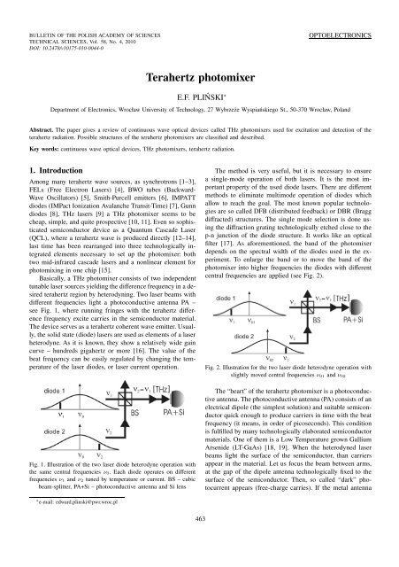
Basically, a THz photomixer consists <strong>of</strong> two independent<br />
tunable laser sources yielding <strong>the</strong> difference frequency in a desired<br />
terahertz region by heterodyning. Two laser beams with<br />
different frequencies light a photoconductive antenna PA –<br />
see Fig. 1, where running fringes with <strong>the</strong> terahertz difference<br />
frequency excite carries in <strong>the</strong> semiconductor material.<br />
The device serves as a terahertz coherent wave emitter. Usually,<br />
<strong>the</strong> solid state (diode) lasers are used as elements <strong>of</strong> a laser<br />
heterodyne. As it is known, <strong>the</strong>y show a relatively wide gain<br />
curve – hundreds gigahertz or more [16]. The value <strong>of</strong> <strong>the</strong><br />
beat frequency can be easily regulated by changing <strong>the</strong> temperature<br />
<strong>of</strong> <strong>the</strong> laser diodes, or laser current operation.<br />
Fig. 1. Illustration <strong>of</strong> <strong>the</strong> two laser diode heterodyne operation with<br />
<strong>the</strong> same central frequencies ν0. Each diode operates on different<br />
frequencies ν1 and ν2 tuned by temperature or current. BS – cubic<br />
beam-splitter, PA+Si – photoconductive antenna and Si lens<br />
∗ e-mail: edward.plinski@pwr.wroc.pl<br />
463<br />
The method is very useful, but it is necessary to ensure<br />
a single-mode operation <strong>of</strong> both lasers. It is <strong>the</strong> most important<br />
property <strong>of</strong> <strong>the</strong> used diode lasers. There are different<br />
methods to eliminate multimode operation <strong>of</strong> diodes which<br />
allow to reach <strong>the</strong> goal. The most known popular technologies<br />
are so called DFB (distributed feedback) or DBR (Bragg<br />
diffracted) structures. The single mode selection is done using<br />
<strong>the</strong> diffraction grating technologically etched close to <strong>the</strong><br />
p-n junction <strong>of</strong> <strong>the</strong> diode structure. It works like an optical<br />
filter [17]. As aforementioned, <strong>the</strong> band <strong>of</strong> <strong>the</strong> photomixer<br />
depends on <strong>the</strong> spectral width <strong>of</strong> <strong>the</strong> diodes used in <strong>the</strong> experiment.<br />
To enlarge <strong>the</strong> band or to move <strong>the</strong> band <strong>of</strong> <strong>the</strong><br />
photomixer into higher frequencies <strong>the</strong> diodes with different<br />
central frequencies are applied (see Fig. 2).<br />
Fig. 2. Illustration for <strong>the</strong> two laser diode heterodyne operation with<br />
slightly moved central frequencies ν01 and ν02<br />
The “heart” <strong>of</strong> <strong>the</strong> terahertz photomixer is a photoconductive<br />
antenna. The photoconductive antenna (PA) consists <strong>of</strong> an<br />
electrical dipole (<strong>the</strong> simplest solution) and suitable semiconductor<br />
quick enough to produce carriers in time with <strong>the</strong> beat<br />
frequency (it means, in order <strong>of</strong> picoseconds). This condition<br />
is fulfilled by many technologically elaborated semiconductor<br />
materials. One <strong>of</strong> <strong>the</strong>m is a Low Temperature grown Gallium<br />
Arsenide (LT-GaAs) [18, 19]. When <strong>the</strong> heterodyned laser<br />
beams light <strong>the</strong> surface <strong>of</strong> <strong>the</strong> semiconductor, than carriers<br />
appear in <strong>the</strong> material. Let us focus <strong>the</strong> beam between arms,<br />
at <strong>the</strong> gap <strong>of</strong> <strong>the</strong> dipole antenna technologically fixed to <strong>the</strong><br />
surface <strong>of</strong> <strong>the</strong> semiconductor. Then, so called “dark” photocurrent<br />
appears (free-charge carries). If <strong>the</strong> metal antenna
is polarized with some voltage carriers give a periodical short<br />
circuit for <strong>the</strong> antenna (see Fig. 3). In o<strong>the</strong>r words, <strong>the</strong> antenna<br />
PA converts <strong>the</strong> photocurrent into a THz wave. The described<br />
device is <strong>of</strong>ten called an Auston switch [20–22]. In that way<br />
an optical switch designed is <strong>the</strong> base for <strong>the</strong> operation <strong>of</strong> <strong>the</strong><br />
terahertz emitter.<br />
Fig. 3. Illustration <strong>of</strong> <strong>the</strong> Auston switch operation. Left: a laser beam<br />
(with some beat frequency ν2–ν1) is focused at <strong>the</strong> gap in <strong>the</strong> dipole<br />
antenna creating carriers at <strong>the</strong> plate <strong>of</strong> <strong>the</strong> semiconductor. If <strong>the</strong><br />
antenna is polarized, than as a consequence, carries create a short<br />
circuit. ML – microscopy lens, PA – photoconductive antenna. Right<br />
– equivalent circuit: Vba – bias voltage, P0 – incident power, Jph –<br />
photocurrent, ν2 −ν1 – optical beat frequency, Rph – photoresistance<br />
<strong>of</strong> <strong>the</strong> antenna PA, Cph – capacitance <strong>of</strong> <strong>the</strong> photoconductive gap,<br />
Rra – radiation resistance <strong>of</strong> <strong>the</strong> antenna PA, Mx – symbol <strong>of</strong> <strong>the</strong><br />
photomixer used in <strong>the</strong> paper<br />
THz photomixer – classification attempt. The most<br />
popular THz photomixer consists <strong>of</strong> two independent laser<br />
sources. The frequency band <strong>of</strong> both lasers should give possibility<br />
to tune <strong>the</strong> lasers yielding <strong>the</strong> frequency difference in<br />
<strong>the</strong> THz range. Figure 4 shows <strong>the</strong> scheme <strong>of</strong> <strong>the</strong> THz photomixer.<br />
Both laser sources give a beating frequency ν2 − ν1.<br />
Both laser beams create an interference signal at <strong>the</strong> surface<br />
<strong>of</strong> <strong>the</strong> semiconductor (exciting beam). The fringes obtained<br />
in that way run along <strong>the</strong> semiconductor material giving <strong>the</strong><br />
modulated intensity <strong>of</strong> <strong>the</strong> electrical field at <strong>the</strong> semiconductor<br />
with <strong>the</strong> frequency <strong>of</strong> ν2 −ν1 (e.g. terahertz frequency). If<br />
<strong>the</strong> semiconductor is enough “quick”, it works like an optical<br />
switch AS – Auston switch [20]. The terahertz wave emitted<br />
via a simple, biased with some voltage, dipole antenna<br />
can be applied for imaging or spectroscopy. The THz signal<br />
is detected by a cryo-bolometer, Golay cell or semiconductor<br />
devices.<br />
Fig. 4. Two separate diode laser sources <strong>of</strong> a frequency difference<br />
ν2 − ν1 excite an optical Auston switch AS including a photoconductive<br />
antenna and Si lens. BS – beam splitter, D – detector<br />
The detection <strong>of</strong> <strong>the</strong> THz signal can be accomplished<br />
without <strong>the</strong> detectors aforementioned. The method bases on<br />
so called coherent homodyne detection (explanation in <strong>the</strong><br />
fur<strong>the</strong>r part) [23]. Homodyne, means here <strong>the</strong> arrangement,<br />
E.F. Pliński<br />
where <strong>the</strong> same laser beam operates as an exciting beam and<br />
probing one – see Fig. 5.<br />
Fig. 5. THz photomixer with coherent homodyne detection arrangement.<br />
BS – beam splitter, AS – Auston switch<br />
It is possible to apply, instead <strong>of</strong> two lasers, a cheap,<br />
multimode laser diode (MDL) as a source <strong>of</strong> <strong>the</strong> frequency<br />
difference for excitation <strong>of</strong> <strong>the</strong> photoconductive antenna AS<br />
(see Fig. 6). To obtain a beat frequency between two adjusted<br />
modes, some optical selectors OS (e.g. a Fabry-Perot filter)<br />
are used [24].<br />
Fig. 6. THz photomixer with multimode laser, OS mode selector, AS<br />
Auston switch, and D detector<br />
Figure 7 presents ano<strong>the</strong>r example where a sophisticated<br />
optical selector is used [25]. It is so called a V-shape mirror<br />
VSM and diffraction grating DG, as a specific optical selector<br />
OS – see Fig. 6. These two optical elements create an output<br />
selecting mirror <strong>of</strong> <strong>the</strong> laser diode. The V-shape mirror<br />
reflects only radiation <strong>of</strong> chosen frequencies possible to generate<br />
by <strong>the</strong> laser. We can switch <strong>the</strong> system by displacement<br />
<strong>of</strong> <strong>the</strong> mirror VSM (see <strong>the</strong> figure) perpendicularly to <strong>the</strong><br />
laser beams. In that way <strong>the</strong> laser diode generates on chosen<br />
frequencies νi and νj.<br />
Fig. 7. The arrangement with a multimode laser and V-shape total<br />
reflecting mirror VSM. DG – diffraction grating, AS – Auston<br />
switch, D – detector<br />
Ano<strong>the</strong>r concept <strong>of</strong> using a multimode frequency diode<br />
laser is similar to that in comb lasers [26]. The pulses obtained<br />
(see Fig. 8) can be applied in <strong>the</strong> same way as in Time<br />
Domain Spectroscopy (TDS) [27, 28] or THz imaging [29].<br />
Fig. 8. Multimode laser comb in TDS measurements<br />
464 Bull. Pol. Ac.: Tech. 58(4) 2010
A dual wavelength laser diode using <strong>the</strong> hopping mode is<br />
possible to use in THz technique and worth to consider [30].<br />
The mode hop in <strong>the</strong> multimode laser diode MLD is obtained<br />
by <strong>the</strong> use <strong>of</strong> a laser diode current control (as known <strong>the</strong> wavelength<br />
<strong>of</strong> <strong>the</strong> MLD varies with <strong>the</strong> injection current). Figure 9<br />
illustrates schematically <strong>the</strong> method. The system requires no<br />
external optical parts but only current and temperature control.<br />
Fig. 9. The system where <strong>the</strong> laser diode injection current JI releases<br />
<strong>the</strong> inter-mode hops<br />
Integrated laser diodes, instead <strong>of</strong> two separate ones, can<br />
also be used in <strong>the</strong> THz photomixer arrangement (see Fig. 10).<br />
Fig. 10. THz photomixer with technologically integrated two laser<br />
sources<br />
The most mature device, where all three elements are<br />
technologically integrated in one chip are two cascade midinfrared<br />
lasers with nonlinear medium Mx monolithically integrated<br />
in <strong>the</strong> active medium (Fig. 11) [31].<br />
Fig. 11. Technologically integrated three elements: two mid-infrared<br />
cascade lasers or photodiodes with some frequency difference and<br />
suitable nonlinear material as a mixer Mx<br />
2. THz photomixer. Design<br />
The terahertz wave created in <strong>the</strong> dipole antenna shows tendency<br />
to be reflected from <strong>the</strong> walls <strong>of</strong> <strong>the</strong> semiconductor<br />
plate. The wave leaves <strong>the</strong> semiconductor if it is joined to<br />
some material with similar refractive index (about 3.4). The<br />
condition fulfils high resistivity silicon (about 10 kΩcm). It<br />
is formed as a lens, which collimates <strong>the</strong> wave. But hemispherical<br />
shape <strong>of</strong> <strong>the</strong> lens still creates problems with internal<br />
reflections (see Fig. 12).<br />
Terahertz photomixer<br />
Fig. 12. Photoconductive antenna PA fixed to a hemispherical lens<br />
Si. ML – microscopy lens<br />
The problem is solved when a hyperhemispherical Si lens<br />
is applied (Fig. 13).<br />
Fig. 13. Hyperhemispherical Si lens apllied to a photoconductive<br />
antenna PA<br />
Many problems with <strong>the</strong> correct adjusting <strong>of</strong> <strong>the</strong> photomixing<br />
system can be solved by <strong>the</strong> application <strong>of</strong> fibers<br />
guiding <strong>the</strong> infrared radiation (exciting and probing beams)<br />
to photoconductive antennas PA (see Fig. 14). Pr<strong>of</strong>essional<br />
products on <strong>the</strong> market are equipped with fibers [32].<br />
Fig. 14. The exciting beam is delivered to a photoconductive antenna<br />
with a fiber fixed directly to PA. The same solution is applied to <strong>the</strong><br />
probing beam<br />
The complete arrangement <strong>of</strong> <strong>the</strong> THz photomixer is<br />
shown in Fig. 15. The photoconductive antenna PA is polarized<br />
with some dc voltage or (much better solution) with<br />
square voltage pulses (a few tens <strong>of</strong> Volts) with relatively<br />
low frequency (from hundreds Hz to a few kHz). The THz<br />
wave is collimated and focused with polyethylene lenses PL<br />
on <strong>the</strong> sample. The set <strong>of</strong> lenses focuses <strong>the</strong> THz beam on<br />
cryo-detector BC.<br />
Fig. 15. Photomixer with a cryo-bolometer BC. Laser heterodyne is<br />
protected against parasitic back-scattering with optical isolators OI.<br />
PA – photoconductive antenna, Si – silicon lens, ML – microscopy<br />
lens, PL – polyethylene lens<br />
Bull. Pol. Ac.: Tech. 58(4) 2010 465
The cryo-detector gives a good signal-to-noise ration but<br />
is not comfortable and not portable. One <strong>of</strong> <strong>the</strong> solution is<br />
a room temperature detector (Golay cell) or using so called<br />
coherent homodyne detection. The same laser beam modulated<br />
with THz frequency (exciting beam) is used as a probing<br />
beam – see Fig. 5. It excites ano<strong>the</strong>r (very <strong>of</strong>ten identical)<br />
photoconductive antenna AS creating carriers, and, as a result,<br />
giving not zero average voltage signal at <strong>the</strong> receiving<br />
dipole antenna [10, 23].<br />
Fig. 16. Coherent homodyne detection. OI – optical isolator, ML<br />
– microscopy lens, EC – emitting chip, RC – receiving chip, PL –<br />
polyethylene lens<br />
Figure 16 explains <strong>the</strong> method. In <strong>the</strong> case <strong>of</strong> <strong>the</strong> unbalanced<br />
arms <strong>of</strong> a difference ∆d, when we change <strong>the</strong> beat<br />
frequency νTHz, or in o<strong>the</strong>r words, <strong>the</strong> frequency <strong>of</strong> <strong>the</strong> THz<br />
wave, we observe a periodical signal Idet at <strong>the</strong> receiving chip<br />
due to variable phase relations between <strong>the</strong> THz ray ETHz<br />
and detecting beam Popt – <strong>the</strong> consequence <strong>of</strong> <strong>the</strong> coherent<br />
detection – see Eq. 1 [10, 18]:<br />
<br />
νTHz<br />
〈Idet〉 ∝ Popt · ETHz · cos<br />
c ∆d<br />
<br />
. (1)<br />
When <strong>the</strong> receiving chip RC is illuminated with heterodyned<br />
laser beams, than it works like an optical switch. It<br />
gives a short circuit for <strong>the</strong> antenna it means it increases and<br />
decreases periodically (with <strong>the</strong> heterodyne frequency) a detectivity<br />
<strong>of</strong> <strong>the</strong> antenna. In that way, <strong>the</strong> non zero average<br />
signal 〈Idet〉 is obtained at <strong>the</strong> receiving chip (see Fig. 17).<br />
The signal can be easy detected using a conventional synchronous<br />
detection method using a lock-in amplifier [21, 33].<br />
Fig. 17. The idea <strong>of</strong> coherent homodyne detection. a) ETHz – THz<br />
ray, b) Popt – detecting beam, c) Idet – signal at <strong>the</strong> receiving chip,<br />
〈Idet〉 – nonzero average signal<br />
E.F. Pliński<br />
3. THz photomixer. Adjusting<br />
The terahertz photomixer, as many optic devices, needs careful<br />
adjusting. A first problem is a suitable lens to focus infrared<br />
radiation <strong>of</strong> <strong>the</strong> laser diodes at <strong>the</strong> surface <strong>of</strong> <strong>the</strong> photoconductive<br />
antenna PA. Usually it is a good quality microscopy<br />
lens ML. The next problem is correct placing <strong>of</strong><br />
<strong>the</strong> antenna PA at <strong>the</strong> surface <strong>of</strong> <strong>the</strong> silicon lens Si, what is<br />
illustrated and explained in Fig. 18.<br />
Fig. 18. Adjusting <strong>of</strong> <strong>the</strong> chips: left – correct, right – wrong. PA –<br />
photoconductive antenna, ML – microscopy mirror, Si – silicon lens<br />
The material <strong>of</strong> <strong>the</strong> lens should suit <strong>the</strong> refractive index<br />
<strong>of</strong> <strong>the</strong> antenna PA (in <strong>the</strong> case <strong>of</strong> <strong>the</strong> LT-GaAs it is about<br />
3.40). It fulfills a high resistivity silicon: about 10 kΩ·cm. So<br />
high refractive index creates <strong>the</strong> focus for <strong>the</strong> terahertz beam<br />
in a different place than <strong>the</strong> focus <strong>of</strong> <strong>the</strong> infrared beam. Figure<br />
19 explains <strong>the</strong> problem. It is why <strong>the</strong> pair lenses (ML<br />
and Si), like at <strong>the</strong> figure, should be moved <strong>of</strong> <strong>the</strong> distance d<br />
to <strong>the</strong> direction <strong>of</strong> <strong>the</strong> THz part <strong>of</strong> <strong>the</strong> photomixer.<br />
Fig. 19. Position <strong>of</strong> <strong>the</strong> setup: ML – microscopy lens, Si – silicon<br />
lens, d – displacement <strong>of</strong> <strong>the</strong> THz beam focus<br />
The terahertz beam, to make it useful, can be led to a measurement<br />
place <strong>of</strong> <strong>the</strong> THz system with polyethylene lenses<br />
(Fig. 20). It is a common solution. The advantage <strong>of</strong> <strong>the</strong> lenses<br />
is a low cost <strong>of</strong> <strong>the</strong> optical system; <strong>the</strong> disadvantage –<br />
relatively high spot <strong>of</strong> <strong>the</strong> beam in <strong>the</strong> focus.<br />
Fig. 20. Polyethylene lenses PL<br />
Ano<strong>the</strong>r popular system uses <strong>of</strong>f-axis parabolic total reflecting<br />
metal mirrors (Fig. 21). It gives acceptable focus (especially<br />
for terahertz imaging applications), but it is relatively<br />
466 Bull. Pol. Ac.: Tech. 58(4) 2010
difficult to adjust. One <strong>of</strong> <strong>the</strong> method is to use a standard single<br />
mode laser (a He-Ne laser or one <strong>of</strong> <strong>the</strong> laser diodes <strong>of</strong><br />
<strong>the</strong> laser heterodyne) and so called “zero” diaphragm. In that<br />
way it is possible to obtain easy observable pattern <strong>of</strong> <strong>the</strong><br />
diffraction fringes. The mirrors should be adjusted so long to<br />
obtain not disturbed pattern <strong>of</strong> <strong>the</strong> fringes along all path <strong>of</strong><br />
<strong>the</strong> terahertz beam. The figure explains <strong>the</strong> procedure.<br />
Fig. 21. Off-axis parabolic mirrors PM. 0-Dia – “zero” diaphragm<br />
4. O<strong>the</strong>r solutions<br />
One <strong>of</strong> possible method to design a dual source <strong>of</strong> frequencies<br />
is a multimode laser with a pre-selection <strong>of</strong> two modes. O<strong>the</strong>r<br />
solution bases on more or less integrated dual sources <strong>of</strong> <strong>the</strong><br />
laser radiation. We can recognize two general kinds <strong>of</strong> <strong>the</strong> devices:<br />
laser-microchips with external photomixing (two in one<br />
plus photomixing), and microchips with internal photomixing<br />
(three in one).<br />
Multimode laser. The application <strong>of</strong> <strong>the</strong> multimode laser<br />
diode MLD as a source for <strong>the</strong> terahertz photomixing seems<br />
to be <strong>the</strong> simplest and <strong>the</strong> cheapest. As known, we can expect<br />
many optical beats between different modes. Mixing many<br />
laser modes creates sharp envelops <strong>of</strong> <strong>the</strong> mixed frequencies<br />
with some repetition rates depending on <strong>the</strong> mode distance<br />
[34–36]. A number <strong>of</strong> <strong>the</strong> beats depends on <strong>the</strong> optical spectrum<br />
<strong>of</strong> <strong>the</strong> laser diode used in <strong>the</strong> experiment. The method<br />
uses just a rich contents <strong>of</strong> <strong>the</strong> multimode beats [27]. In that<br />
way it is possible to obtain a broad spectrum in THz band as<br />
a broadband radiation source for THz-TDS (Terahertz Time<br />
Domain Spectroscopy) [28]. The THz radiation is detected<br />
in a classical way using <strong>the</strong> cross-correlational heterodyning<br />
between <strong>the</strong> generated THz waves and <strong>the</strong> multimode laser<br />
beam on <strong>the</strong> photoconductive antenna PA in <strong>the</strong> setup like in<br />
Fig. 8.<br />
Multimode laser with a pre-selection. The multimode<br />
laser can be preselected to obtain a dual mode laser. Figure 22<br />
shows <strong>the</strong> idea in a schematic way. The beat frequency ν2−ν1<br />
is applied in <strong>the</strong> same way as it is illustrated in Fig. 6. The selection<br />
<strong>of</strong> <strong>the</strong> two modes can be accomplished with a suitable<br />
mode selector (e.g. an etalon) [24].<br />
Fig. 22. Illustration for multimode laser diode with mode selection<br />
using an etalon<br />
Terahertz photomixer<br />
Dual color laser diodes. A dual-color laser diode is an<br />
integrated structure <strong>of</strong> two diodes. Each <strong>of</strong> <strong>the</strong> diodes operate<br />
on slightly different wavelengths and in that way <strong>the</strong> desired<br />
difference frequency is obtained and applied as a source for<br />
<strong>the</strong> photomixer [17, 37]. The advantage is simplicity <strong>of</strong> <strong>the</strong><br />
photomixer arrangement. As <strong>the</strong>y report [37], <strong>the</strong> monolithic<br />
semiconductor element consists <strong>of</strong> two DFB laser sections<br />
and one phase section between <strong>the</strong> lasers in one chip. The big<br />
advantage <strong>of</strong> <strong>the</strong> device is possibility <strong>of</strong> independent tuning<br />
each <strong>of</strong> <strong>the</strong> laser by adjusting currents. In that way <strong>the</strong> frequency<br />
band from 170 to 490 GHz was reached. Figure 23<br />
schematically illustrates <strong>the</strong> idea.<br />
Fig. 23. Illustration for <strong>the</strong> dual laser diode operation. The mixer is<br />
still outside <strong>of</strong> <strong>the</strong> dual color chip<br />
Two-color cascade lasers with internal photomixing.<br />
Cascade lasers (QCL) needs cooling to about 150 K if <strong>the</strong>y<br />
operate in THz region. It is due to relatively thin layers <strong>of</strong> <strong>the</strong><br />
semiconductor designed for that band <strong>of</strong> <strong>the</strong> frequency. The<br />
problem is illustrated in Fig. 24. Very <strong>of</strong>ten even both devices,<br />
<strong>the</strong> THz QCL and <strong>the</strong> detector, are cooled to helium temperature.<br />
The problem is less difficult in <strong>the</strong> medium frequency<br />
band, when <strong>the</strong> cascade lasers operate at room temperature,<br />
and this idea was <strong>the</strong> base for <strong>the</strong> successful solution.<br />
Fig. 24. Illustration for <strong>the</strong> arrangement with a cascade laser CLC<br />
and detector (bolometer) BC – both in cryostats, PL – polyethylene<br />
lens<br />
A Federico Capasso group <strong>of</strong> <strong>the</strong> Harvard School <strong>of</strong> Engineering<br />
and Applied <strong>Sciences</strong> and colleagues from Texas<br />
A&M University and ETH Zurich demonstrated in 2008 year<br />
a sophisticated structure <strong>of</strong> two integrated room temperature<br />
mid-infrared cascade lasers. The lasers worked on 33.7 THz<br />
(8.9-micron wavelength) and 28.5 THz (10.5-micron wavelength)<br />
yielding a difference frequency <strong>of</strong> 5.2 THz. This dual<br />
frequency cascade laser chip was technologically equipped<br />
with a nonlinear material, which generated <strong>the</strong> frequency difference<br />
(see Fig. 25). In that way a “room-temperature terahertz<br />
laser” was invented [31].<br />
Bull. Pol. Ac.: Tech. 58(4) 2010 467
Fig. 25. Scheme <strong>of</strong> two room temperature medium frequency cascade<br />
lasers (or laser diodes) technologically integrated with a frequency<br />
mixer<br />
Frequency stability aspects. A frequency stability <strong>of</strong> THz<br />
photomixer systems depends on many factors. The main factor<br />
which influences <strong>the</strong> stability is temperature <strong>of</strong> diodes or<br />
o<strong>the</strong>r lasers used in <strong>the</strong> system. The system shown in Fig. 4 is<br />
equipped with two separated and independently cooled laser<br />
diodes. Theoretically <strong>the</strong>y can be tuned with temperature with<br />
a step <strong>of</strong> 0.002 ◦ C, what gives tuning <strong>of</strong> appr. 50 MHz. In practice<br />
<strong>the</strong> frequency stability reaches <strong>the</strong> values between 1 GHz<br />
and 5 GHz. For THz imaging applications it does not have any<br />
meaning. For spectroscopy applications it allows to recognize<br />
most <strong>of</strong> investigated spectral lines. Systems shown in Fig. 10,<br />
11, 23, and 25 are more stable by technological integration <strong>of</strong><br />
<strong>the</strong> lasers.<br />
5. Some results<br />
The terahertz photomixer consists <strong>of</strong> two optical arms: an exciting<br />
beam (including a terahertz path) and probing beam<br />
(Fig. 26). Typically, <strong>the</strong> both arms are <strong>of</strong> <strong>the</strong> same length,<br />
what is ensured by tuning <strong>the</strong> delay line. We consider ano<strong>the</strong>r<br />
case, where <strong>the</strong> lengths <strong>of</strong> <strong>the</strong> arms are unbalanced. It is<br />
obvious, that such a system behaves like an interferometer. It<br />
E.F. Pliński<br />
means, when <strong>the</strong> frequency <strong>of</strong> <strong>the</strong> source (laser diode heterodyne)<br />
is changed, than we observe a quasi-sinusoidal signal<br />
(see Fig. 27)<br />
Fig. 26. A typical arrangement <strong>of</strong> a THz photomixer, where <strong>the</strong><br />
coherent detection method is applied. EPA – emitting photoconductive<br />
antenna, RPA – receiving photoconductive antenna, BS – cubic<br />
beamsplitter, PM – parabolic mirrors<br />
The length difference ∆d between <strong>the</strong> probing and exciting<br />
beams could be easy calculated from <strong>the</strong> period in <strong>the</strong><br />
frequency domain measurement shown in Fig. 27. When we<br />
place <strong>the</strong> sample in <strong>the</strong> THz arm <strong>of</strong> <strong>the</strong> system, than <strong>the</strong><br />
length difference ∆d is different. The difference between both<br />
measurements can be easy recalculated into <strong>the</strong> value <strong>of</strong> <strong>the</strong><br />
refractive index <strong>of</strong> <strong>the</strong> measured sample.<br />
To make results more precise we can calculate a Fourier<br />
transform from <strong>the</strong> signal like in Fig. 27 (but <strong>the</strong> method<br />
is reliable for non-dispersive materials <strong>of</strong> <strong>the</strong> measured samples)<br />
[38].<br />
Fig. 27. A typical signal (amplitude – top, and phase – bottom) obtained from <strong>the</strong> lock-in amplifier when <strong>the</strong> frequency <strong>of</strong> <strong>the</strong> photomixer<br />
is tuned from appr. 0.1 to 0.75 THz<br />
468 Bull. Pol. Ac.: Tech. 58(4) 2010
6. Conclusions<br />
The terahertz photomixer, as a continuous wave spectrometer,<br />
can be competitive for pulse arrangements. Firstly, pulse THz<br />
spectrometers using <strong>the</strong> method <strong>of</strong> THz-TDS (Time Domain<br />
Spectroscopy) are relatively expensive because <strong>of</strong> <strong>the</strong> femtosecond<br />
laser as <strong>the</strong> element <strong>of</strong> <strong>the</strong> arrangement. Secondly,<br />
continuous wave setups can show a better resolution comparing<br />
to pulse systems (see e.g. cw systems equipped with<br />
quantum cascade lasers) [12–14]. It can be relatively easily<br />
applied to terahertz wide-band communications [39]. On <strong>the</strong><br />
o<strong>the</strong>r hand, pulse systems achieve wide band <strong>of</strong> <strong>the</strong> terahertz<br />
spectrum including medium infrared [40].<br />
Acknowledgements. The author wants to express his gratitude<br />
to Dr. R. Wilk for many fruitful discussions. The author<br />
is also grateful to Dr. M. Mikulics and Dr. M. Marso for <strong>the</strong>ir<br />
help in <strong>the</strong> fabrication <strong>of</strong> photoconductive antennas. The author<br />
would like to acknowledge <strong>the</strong> help <strong>of</strong> Dr. J. Witkowski<br />
with useful discussions and also <strong>the</strong> help <strong>of</strong> Dr. A. Grobelny<br />
with <strong>the</strong> device design. Also great thanks to MSc. P. Jarząb<br />
and MSc. K. Nowak for <strong>the</strong>ir help in composing <strong>the</strong> terahertz<br />
photomixer and measurements. The author would like to thank<br />
Dr. G. Beziuk for his help with <strong>the</strong> electronic components <strong>of</strong><br />
<strong>the</strong> terahertz system. Author is also grateful to pr<strong>of</strong>. M. Koch<br />
and his staff for hospitality.<br />
REFERENCES<br />
[1] J.M. Byrd, W. Leemans, A. L<strong>of</strong>tsdottir, B. Marcelis, M.C. Martin,<br />
W.R. McKinney, F. Sannibale, T. Scarvie, and C. Steier,<br />
“Observation <strong>of</strong> broadband self-amplified spontaneous coherent<br />
terahertz synchrotron radiation in a storage ring”, Phys.<br />
Rev. Lett. 89, 224801–5 (2002).<br />
[2] J.M. Byrd, Michael C. Martin, W.R. McKinney, D.V. Munson,<br />
H. Nishimura, D.S. Robin, F. Sannibale, R.D. Schlueter, W.G.<br />
Thur, J.Y. Jung, and W. Wan, “CIRCE: a dedicated storage<br />
ring for coherent THz synchrotron radiation”, Infrared Physics<br />
& Technology 45, 325–330 (2004).<br />
[3] E. Karantzoulis, G. Penco, A. Perucchi, and S. Lupi, “Coherent<br />
THz radiation at ELETTRA”, Proc. EPAC08 1, CD-ROM<br />
(2008).<br />
[4] M. Tecimer, L.C. Brunel, and J. van Tol, “A designed study<br />
<strong>of</strong> a FIR/THZ FEL for high magnetic field”, Proc. FEL 1,<br />
CD-ROM (2006).<br />
[5] B. Gorshunov, A. Volkov, I. Spektor, A. Prokhorov, A. Mukhin,<br />
M. Dressel, S. Uchida, and A. Loidl, “Terahertz BWOspectrosopy”,<br />
Int. J. Infrared and Millimeter Waves 26 (9),<br />
1217–1240 (2005).<br />
[6] G. Kube, H. Backe, W. Lauth, and H. Schoepe, “Smith-Purcell<br />
radiation in view <strong>of</strong> particle beam diagnostic”, Proc. DIPAC<br />
1, CD-ROM (2008).<br />
[7] M. Mukherjee and N. Mazumder, “Photo-illuminated InP Terahertz<br />
IMPATT device”, Indium Phosphide & Related Materials,<br />
19th IEEE Int. Conf. 1, CD-ROM (2008).<br />
[8] N. Karpowicz, H. Zhong, C. Zhang, K.-I Lin, J.-S. Hwang,<br />
J. Xu, and X.-C. Zhang, “Compact continuous-wave subterahertz<br />
system for inspection applications”, Appl. Phys. Lett. 86,<br />
054105 (2005).<br />
[9] S.C. Zerbetto, L.R. Zink, K.M. Evenson, and E.C.C. Vasconcellos,<br />
“Frequency measurements <strong>of</strong> 3 to 11 THz laser lines <strong>of</strong><br />
Terahertz photomixer<br />
CH3OH”, Int. J. Infrared and Millimeter Waves 17 (6), 1049–<br />
1054 (2005).<br />
[10] D. Mittleman, Sensing with THz Radiation, Springer, Berlin,<br />
2003.<br />
[11] E.R., Brown, K.A., McIntosh, K.B Nichols, and C.L Dennis,<br />
“Photomixing up to 3.8 THz in low-temperature-grown GaAs”,<br />
Appl. Phys. Lett. 66, 285–287 (1994).<br />
[12] A.A. Kosterev, R.F. Curl, and F.K. Tittel, “Chemical sensors using<br />
quantum cascade lasers”, Laser Physics 11, 39–49 (2001).<br />
[13] A.A. Kosterev and F.K. Tittel, “Chemical sensors based on<br />
quantum cascade lasers”, IEEE J. Quant. Electron. QE-38 (6),<br />
582–591 (2002).<br />
[14] G. Wysocki, R. Lewicki, R.F. Curl, F.K. Tittel, L. Diehl, F. Capasso,<br />
M. Troccoli, G. H<strong>of</strong>ler, D. Bour, S. Corzine, R. Maulini,<br />
M. Giovannini, and J. Faist, “Widely tunable mode-hop<br />
free external cavity quantum cascade lasers for high resolution<br />
spectroscopy and chemical sensing”, Appl. Physics B: Lasers<br />
and Optics 92, 305 (2008).<br />
[15] M.A. Belkin, F. Capasso, F. Xie, A. Belyanin, M. Fischer,<br />
A. Wittmann, and J. Faist, “Room temperature terahertz quantum<br />
cascade laser source based on intracavity difference-frequency<br />
generation” , Appl. Physics Letters 92, 201101 (2008).<br />
[16] D. Sands, Diode Lasers, Taylor & Francis; London, 2004.<br />
[17] A. Klehr, J. Fricke, A. Knauer, G. Erbert, M. Wal<strong>the</strong>r, R. Wilk,<br />
M. Mikulics, and M. Koch, “High-power monolithic two-mode<br />
DFB laser diodes for <strong>the</strong> generation <strong>of</strong> THz radiation”, IEEE<br />
J. Sel. Top. Quant. Electron. 14 (2), 289–294 (2008).<br />
[18] S. Kiyomi, “Terahertz optoelectronics”, Series: Topics in Applied<br />
Physics 97, 1–400 (2005).<br />
[19] P. Kordoˇs, M. Marso, and M. Mikulics, “Performance optimization<br />
<strong>of</strong> GaAs-based photomixers as sources <strong>of</strong> THz radiation”,<br />
Appl. Phys. A 87, 563–567 (2007).<br />
[20] D.H. Auston, K.P. Cheung, and P.R. Smith, “Picosecond photoconductive<br />
Hertzian dipoles”, Appl. Phys. Lett. 45, 284–286<br />
(1984).<br />
[21] Th. Pfeiffer, J. Kuhl, M. Serenyi, H.-U. Habermeier, E.0. Gobel,<br />
L. Palmetsh<strong>of</strong>er, and A. Axmann, “Picosecond optoelectronic<br />
switches”, Physica Scripta. T13, 100–103 (1986).<br />
[22] P.R. Smith, D.H. Auston, and M.C. Nuss, “Subpicosecond photoconducting<br />
dipole antennas”, IEEE J. Quant. Electron. QE-<br />
24 (2), 255–260 (1988).<br />
[23] E.F. Plinski, R. Wilk, and M. Mikulics, “Terahertz optical mixer<br />
design”, Phot. Lett. Pol. 1 (1), 28–30 (2009).<br />
[24] U. Willer, R. Wilk, W. Schippers, S. Böttger, D. Nodop,<br />
T. Schossig, W. Schade1, M. Mikulics, M. Koch, M. Wal<strong>the</strong>r,<br />
H. Niemann, and B. Güttler, “A novel THz source based on<br />
a two-color Nd:LSB microchip-laser and a LT-GaAsSb photomixer”,<br />
Appl. Phys. B: Lasers and Optics 87 (1), 13–16<br />
(2007).<br />
[25] S. H<strong>of</strong>fmann, M. H<strong>of</strong>mann, E. Bründermann, M. Havenith,<br />
M. Matus and J.V. Moloney, A.S. Moskalenko, M. Kira,<br />
S.W. Koch, S. Saito, and K. Sakai, “Four-wave mixing and direct<br />
terahertz emission with two-color semiconductor lasers”,<br />
Appl. Phys. Lett. 84 (18), 3585–3587 (2004).<br />
[26] T. Steinmetz, T. Wilken, C. Araujo-Hauck, R. Holzwarth, T.W.<br />
Hänsch, L. Pasquini, A. Manesceau, S. Odorico, M.T. Murphy,<br />
T. Kentischer, W. Schmidt, and Th. Udem, “Laser frequency<br />
combs for astronomical observations”, Science 321, 1335–1337<br />
(2008).<br />
[27] M. Tani, O. Morikawa, S. Matsuura, and M. Hango, “Generation<br />
<strong>of</strong> terahertz radiation by photomixing with dual- and<br />
multiple-mode lasers”, Sem. Sc. Tech. 20, S151–S163 (2005).<br />
Bull. Pol. Ac.: Tech. 58(4) 2010 469
[28] M. Scheller and M. Koch, “Terahertz quasi time domain spectroscopy”,<br />
Opt. Expr. 17, 17723–17733 (2009).<br />
[29] K. Shibuya, M. Tani, M. Hangyo, O. Morikawa, and<br />
H. Kan, “Compact and inexpensive continuous-wave subterahertz<br />
imaging system with a fiber-coupled multimode laser<br />
diode”, Appl. Phys. Lett. 90, 161127 (2007).<br />
[30] T. Suzuki, N. Hido, X. Zhao, and O. Sasaki, „Dual-color operation<br />
<strong>of</strong> a laser diode under current and temperature control”,<br />
Appl. Opt. 42 (33), 6640–6644 (2003).<br />
[31] M.A. Belkin, F. Capasso, F. Xie, A. Belyanin, M. Fisher,<br />
A. Wittmann, and J. Faist, “Room temperature terahertz quantum<br />
cascade laser source based on intracavity differencefrequency<br />
generation”, Appl. Phys. Lett. 92, 201101–3 (2008).<br />
[32] Y.D. Gong, M.Y.W. Chia, and B. Luo, “Terahertz spectroscopy<br />
technology trend using 1550-nm ultrafast fiber laser”, Micr.<br />
Opt. Tech. Lett. 49, 439–443 (2007).<br />
[33] G. Mouret , S. Matton, R. Bocquet, D. Bigourd, F. Hindle,<br />
A. Cuisset, J.F. Lampin, K. Blary, and D. Lippens, “THz media<br />
characterization by means <strong>of</strong> coherent homodyne detection,<br />
results and potential applications”, Appl. Phys. B: Lasers and<br />
Optics 89 (2–3), 395–399 (2007).<br />
[34] O. Morikawa, M. Tonouchi, and M. Hangyo, “Sub-THz spectroscopic<br />
system using a multimode laser diode and photoconductive<br />
antenna”, Appl. Phys. Lett. 75, 3772–3774 (1999).<br />
E.F. Pliński<br />
[35] S. Latkowski, F. Surre, and P. Landais, “Terahertz wave generation<br />
from a dc-biased multimode laser”, Appl. Phys. Lett. 92,<br />
081109 (2008).<br />
[36] S. Latkowski, F. Surre, R. Maldonado-Basilio, and P. Landaisa,<br />
“Investigation on <strong>the</strong> origin <strong>of</strong> terahertz waves generated by dcbiased<br />
multimode semiconductor lasers at room temperature”,<br />
Appl. Phys. Lett. 93, 241110 (2008).<br />
[37] N. Kim, J. Shin, E. Sim, C.W. Lee, D-S. Yee, M.Y. Jeon,<br />
Y. Jang, and K.H. Park, “Monolithic dual-mode distributed<br />
feedback semiconductor laser for tunable continuous-wave terahertz<br />
generation”, Opt. Expr. 17, 13851–13859 (2009).<br />
[38] J.S. Witkowski, P. Jarząb, K. Nowak, R. Wilk, M. Mikulics,<br />
and E.F. Pliński, “Fourier transform in THz measurements <strong>of</strong><br />
refractive index”, IRMMW-THz, 34th Int. Conf. on Infrared,<br />
Millimeter, and Terahertz Waves 1, CD-ROM (2009).<br />
[39] C. Jastrow, K. Münter, R. Piesiewicz, T. Kürner, M. Koch, and<br />
T. Kleine-Ostmann, “300 GHz transmission system”, Electr.<br />
Lett. 44 (3), 214–215 (2008).<br />
[40] Q. Guo, Y. Kume, Y. Fukuhara, T. Tanaka, M. Nishio,<br />
H. Ogawa, M. Hiratsuka, M. Tani, and M. Hango, „Observation<br />
<strong>of</strong> ultra-broadband terahertz emission from ZnTe films<br />
grown by metaloganic vapor epitaxy”, Solid State Communications<br />
141, 188–191 (2007).<br />
470 Bull. Pol. Ac.: Tech. 58(4) 2010