PDF - 5,3 MB - Bulletin of the Polish Academy of Sciences
PDF - 5,3 MB - Bulletin of the Polish Academy of Sciences
PDF - 5,3 MB - Bulletin of the Polish Academy of Sciences

You also want an ePaper? Increase the reach of your titles
YUMPU automatically turns print PDFs into web optimized ePapers that Google loves.
The cryo-detector gives a good signal-to-noise ration but<br />
is not comfortable and not portable. One <strong>of</strong> <strong>the</strong> solution is<br />
a room temperature detector (Golay cell) or using so called<br />
coherent homodyne detection. The same laser beam modulated<br />
with THz frequency (exciting beam) is used as a probing<br />
beam – see Fig. 5. It excites ano<strong>the</strong>r (very <strong>of</strong>ten identical)<br />
photoconductive antenna AS creating carriers, and, as a result,<br />
giving not zero average voltage signal at <strong>the</strong> receiving<br />
dipole antenna [10, 23].<br />
Fig. 16. Coherent homodyne detection. OI – optical isolator, ML<br />
– microscopy lens, EC – emitting chip, RC – receiving chip, PL –<br />
polyethylene lens<br />
Figure 16 explains <strong>the</strong> method. In <strong>the</strong> case <strong>of</strong> <strong>the</strong> unbalanced<br />
arms <strong>of</strong> a difference ∆d, when we change <strong>the</strong> beat<br />
frequency νTHz, or in o<strong>the</strong>r words, <strong>the</strong> frequency <strong>of</strong> <strong>the</strong> THz<br />
wave, we observe a periodical signal Idet at <strong>the</strong> receiving chip<br />
due to variable phase relations between <strong>the</strong> THz ray ETHz<br />
and detecting beam Popt – <strong>the</strong> consequence <strong>of</strong> <strong>the</strong> coherent<br />
detection – see Eq. 1 [10, 18]:<br />
<br />
νTHz<br />
〈Idet〉 ∝ Popt · ETHz · cos<br />
c ∆d<br />
<br />
. (1)<br />
When <strong>the</strong> receiving chip RC is illuminated with heterodyned<br />
laser beams, than it works like an optical switch. It<br />
gives a short circuit for <strong>the</strong> antenna it means it increases and<br />
decreases periodically (with <strong>the</strong> heterodyne frequency) a detectivity<br />
<strong>of</strong> <strong>the</strong> antenna. In that way, <strong>the</strong> non zero average<br />
signal 〈Idet〉 is obtained at <strong>the</strong> receiving chip (see Fig. 17).<br />
The signal can be easy detected using a conventional synchronous<br />
detection method using a lock-in amplifier [21, 33].<br />
Fig. 17. The idea <strong>of</strong> coherent homodyne detection. a) ETHz – THz<br />
ray, b) Popt – detecting beam, c) Idet – signal at <strong>the</strong> receiving chip,<br />
〈Idet〉 – nonzero average signal<br />
E.F. Pliński<br />
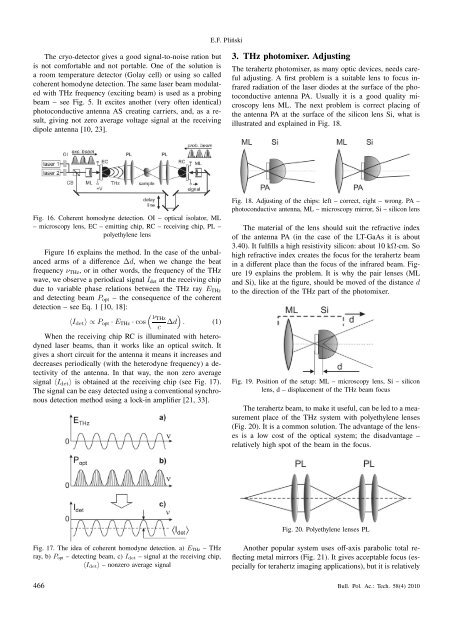
3. THz photomixer. Adjusting<br />
The terahertz photomixer, as many optic devices, needs careful<br />
adjusting. A first problem is a suitable lens to focus infrared<br />
radiation <strong>of</strong> <strong>the</strong> laser diodes at <strong>the</strong> surface <strong>of</strong> <strong>the</strong> photoconductive<br />
antenna PA. Usually it is a good quality microscopy<br />
lens ML. The next problem is correct placing <strong>of</strong><br />
<strong>the</strong> antenna PA at <strong>the</strong> surface <strong>of</strong> <strong>the</strong> silicon lens Si, what is<br />
illustrated and explained in Fig. 18.<br />
Fig. 18. Adjusting <strong>of</strong> <strong>the</strong> chips: left – correct, right – wrong. PA –<br />
photoconductive antenna, ML – microscopy mirror, Si – silicon lens<br />
The material <strong>of</strong> <strong>the</strong> lens should suit <strong>the</strong> refractive index<br />
<strong>of</strong> <strong>the</strong> antenna PA (in <strong>the</strong> case <strong>of</strong> <strong>the</strong> LT-GaAs it is about<br />
3.40). It fulfills a high resistivity silicon: about 10 kΩ·cm. So<br />
high refractive index creates <strong>the</strong> focus for <strong>the</strong> terahertz beam<br />
in a different place than <strong>the</strong> focus <strong>of</strong> <strong>the</strong> infrared beam. Figure<br />
19 explains <strong>the</strong> problem. It is why <strong>the</strong> pair lenses (ML<br />
and Si), like at <strong>the</strong> figure, should be moved <strong>of</strong> <strong>the</strong> distance d<br />
to <strong>the</strong> direction <strong>of</strong> <strong>the</strong> THz part <strong>of</strong> <strong>the</strong> photomixer.<br />
Fig. 19. Position <strong>of</strong> <strong>the</strong> setup: ML – microscopy lens, Si – silicon<br />
lens, d – displacement <strong>of</strong> <strong>the</strong> THz beam focus<br />
The terahertz beam, to make it useful, can be led to a measurement<br />
place <strong>of</strong> <strong>the</strong> THz system with polyethylene lenses<br />
(Fig. 20). It is a common solution. The advantage <strong>of</strong> <strong>the</strong> lenses<br />
is a low cost <strong>of</strong> <strong>the</strong> optical system; <strong>the</strong> disadvantage –<br />
relatively high spot <strong>of</strong> <strong>the</strong> beam in <strong>the</strong> focus.<br />
Fig. 20. Polyethylene lenses PL<br />
Ano<strong>the</strong>r popular system uses <strong>of</strong>f-axis parabolic total reflecting<br />
metal mirrors (Fig. 21). It gives acceptable focus (especially<br />
for terahertz imaging applications), but it is relatively<br />
466 Bull. Pol. Ac.: Tech. 58(4) 2010