PDF - 5,3 MB - Bulletin of the Polish Academy of Sciences
PDF - 5,3 MB - Bulletin of the Polish Academy of Sciences
PDF - 5,3 MB - Bulletin of the Polish Academy of Sciences

Create successful ePaper yourself
Turn your PDF publications into a flip-book with our unique Google optimized e-Paper software.
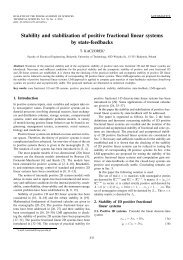
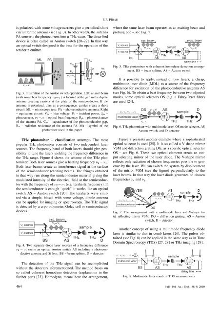
is polarized with some voltage carriers give a periodical short<br />
circuit for <strong>the</strong> antenna (see Fig. 3). In o<strong>the</strong>r words, <strong>the</strong> antenna<br />
PA converts <strong>the</strong> photocurrent into a THz wave. The described<br />
device is <strong>of</strong>ten called an Auston switch [20–22]. In that way<br />
an optical switch designed is <strong>the</strong> base for <strong>the</strong> operation <strong>of</strong> <strong>the</strong><br />
terahertz emitter.<br />
Fig. 3. Illustration <strong>of</strong> <strong>the</strong> Auston switch operation. Left: a laser beam<br />
(with some beat frequency ν2–ν1) is focused at <strong>the</strong> gap in <strong>the</strong> dipole<br />
antenna creating carriers at <strong>the</strong> plate <strong>of</strong> <strong>the</strong> semiconductor. If <strong>the</strong><br />
antenna is polarized, than as a consequence, carries create a short<br />
circuit. ML – microscopy lens, PA – photoconductive antenna. Right<br />
– equivalent circuit: Vba – bias voltage, P0 – incident power, Jph –<br />
photocurrent, ν2 −ν1 – optical beat frequency, Rph – photoresistance<br />
<strong>of</strong> <strong>the</strong> antenna PA, Cph – capacitance <strong>of</strong> <strong>the</strong> photoconductive gap,<br />
Rra – radiation resistance <strong>of</strong> <strong>the</strong> antenna PA, Mx – symbol <strong>of</strong> <strong>the</strong><br />
photomixer used in <strong>the</strong> paper<br />
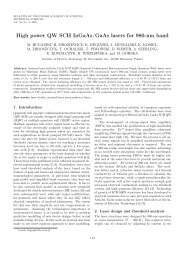
THz photomixer – classification attempt. The most<br />
popular THz photomixer consists <strong>of</strong> two independent laser<br />
sources. The frequency band <strong>of</strong> both lasers should give possibility<br />
to tune <strong>the</strong> lasers yielding <strong>the</strong> frequency difference in<br />
<strong>the</strong> THz range. Figure 4 shows <strong>the</strong> scheme <strong>of</strong> <strong>the</strong> THz photomixer.<br />
Both laser sources give a beating frequency ν2 − ν1.<br />
Both laser beams create an interference signal at <strong>the</strong> surface<br />
<strong>of</strong> <strong>the</strong> semiconductor (exciting beam). The fringes obtained<br />
in that way run along <strong>the</strong> semiconductor material giving <strong>the</strong><br />
modulated intensity <strong>of</strong> <strong>the</strong> electrical field at <strong>the</strong> semiconductor<br />
with <strong>the</strong> frequency <strong>of</strong> ν2 −ν1 (e.g. terahertz frequency). If<br />
<strong>the</strong> semiconductor is enough “quick”, it works like an optical<br />
switch AS – Auston switch [20]. The terahertz wave emitted<br />
via a simple, biased with some voltage, dipole antenna<br />
can be applied for imaging or spectroscopy. The THz signal<br />
is detected by a cryo-bolometer, Golay cell or semiconductor<br />
devices.<br />
Fig. 4. Two separate diode laser sources <strong>of</strong> a frequency difference<br />
ν2 − ν1 excite an optical Auston switch AS including a photoconductive<br />
antenna and Si lens. BS – beam splitter, D – detector<br />
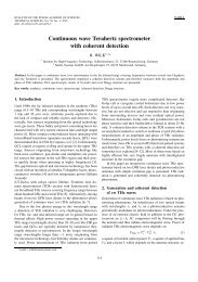
The detection <strong>of</strong> <strong>the</strong> THz signal can be accomplished<br />
without <strong>the</strong> detectors aforementioned. The method bases on<br />
so called coherent homodyne detection (explanation in <strong>the</strong><br />
fur<strong>the</strong>r part) [23]. Homodyne, means here <strong>the</strong> arrangement,<br />
E.F. Pliński<br />
where <strong>the</strong> same laser beam operates as an exciting beam and<br />
probing one – see Fig. 5.<br />
Fig. 5. THz photomixer with coherent homodyne detection arrangement.<br />
BS – beam splitter, AS – Auston switch<br />
It is possible to apply, instead <strong>of</strong> two lasers, a cheap,<br />
multimode laser diode (MDL) as a source <strong>of</strong> <strong>the</strong> frequency<br />
difference for excitation <strong>of</strong> <strong>the</strong> photoconductive antenna AS<br />
(see Fig. 6). To obtain a beat frequency between two adjusted<br />
modes, some optical selectors OS (e.g. a Fabry-Perot filter)<br />
are used [24].<br />
Fig. 6. THz photomixer with multimode laser, OS mode selector, AS<br />
Auston switch, and D detector<br />
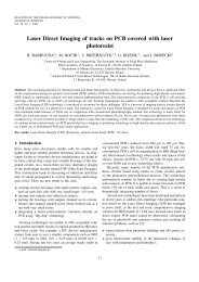
Figure 7 presents ano<strong>the</strong>r example where a sophisticated<br />
optical selector is used [25]. It is so called a V-shape mirror<br />
VSM and diffraction grating DG, as a specific optical selector<br />
OS – see Fig. 6. These two optical elements create an output<br />
selecting mirror <strong>of</strong> <strong>the</strong> laser diode. The V-shape mirror<br />
reflects only radiation <strong>of</strong> chosen frequencies possible to generate<br />
by <strong>the</strong> laser. We can switch <strong>the</strong> system by displacement<br />
<strong>of</strong> <strong>the</strong> mirror VSM (see <strong>the</strong> figure) perpendicularly to <strong>the</strong><br />
laser beams. In that way <strong>the</strong> laser diode generates on chosen<br />
frequencies νi and νj.<br />
Fig. 7. The arrangement with a multimode laser and V-shape total<br />
reflecting mirror VSM. DG – diffraction grating, AS – Auston<br />
switch, D – detector<br />
Ano<strong>the</strong>r concept <strong>of</strong> using a multimode frequency diode<br />
laser is similar to that in comb lasers [26]. The pulses obtained<br />
(see Fig. 8) can be applied in <strong>the</strong> same way as in Time<br />
Domain Spectroscopy (TDS) [27, 28] or THz imaging [29].<br />
Fig. 8. Multimode laser comb in TDS measurements<br />
464 Bull. Pol. Ac.: Tech. 58(4) 2010