RTM 351
RTM 351
RTM 351

Create successful ePaper yourself
Turn your PDF publications into a flip-book with our unique Google optimized e-Paper software.
A Company<br />
of ThyssenKrupp<br />
Technologies<br />
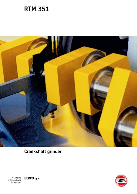
<strong>RTM</strong> <strong>351</strong><br />
Crankshaft grinder<br />
BERCO S.p.A.
The machine and its executions<br />
The <strong>RTM</strong><strong>351</strong> Crankshaft Grinder,<br />
conceived and realized according<br />
to highly innovatory criteria, is a<br />
structurally balanced and highly<br />
reliable machine, whose main<br />
features are the utmost precision<br />
and the top flexibility. Designed<br />
for the internal-combustion<br />
engine crankshaft reconditioning,<br />
it can, on request, be tooled up<br />
also for cylindrical grinding.<br />
The <strong>RTM</strong><strong>351</strong> is available in two<br />
executions:<br />
“A” execution, suitable for<br />
regrinding crankshaft with<br />
different features and dimensions;<br />
“D” execution, same as the “A”<br />
execution but equipped with an<br />
electro-hydraulic appliance which<br />
allows also grinding of cylindrical<br />
components such as rollers, bars,<br />
etc.<br />
In order to meet the manifold<br />
work requirements, the two<br />
1 Wheelhead plunge feed control<br />
panel.<br />
2 Table traverse control<br />
handwheel.<br />
3 Fast table traverse control<br />
lever.<br />
1<br />
2<br />
3<br />
4<br />
5<br />
6<br />
executions are available with two<br />
different center-to-center<br />
distances named <strong>RTM</strong><strong>351</strong>/2400<br />
and <strong>RTM</strong><strong>351</strong>/3000.<br />
The <strong>RTM</strong><strong>351</strong>, as it comes<br />
complete with its standard outfit,<br />
can immediately be used for<br />
profitable operation.<br />
Its performances are boosted by<br />
the addition of special devices<br />
such as: attachment for “in<br />
process” gauging (mechanical or<br />
hydraulic), hydraulic wheelhead<br />
plunge feed, hydraulic wheel<br />
dresser, etc.<br />
The main technical and<br />
construction features of the<br />
<strong>RTM</strong><strong>351</strong> are:<br />
• Top geometric precision and<br />
surface finish of the<br />
workpiece being ground<br />
because of the extreme<br />
sensitivity of the table<br />
movements and the<br />
5 Faceplate lock knob.<br />
6 Trip stop for automatic table<br />
traverse reverse.<br />
7 Hydraulic wheel dresser.<br />
8 Electronic “in process” sizing<br />
gauge.<br />
stiffness of the wheelhead<br />
assembly whose<br />
wheelspindle is supported,<br />
on 50% of its length, by<br />
special babbited bearing;<br />
• Air-float headstock and<br />
tailstock;<br />
• Workheads with four<br />
movements; radial and<br />
cross movements, 360°<br />
rotary motion and<br />
micrometer swing<br />
movement, for easy and<br />
fast centering of crankpins.<br />
Readings on workhead to<br />
hundredths of a mm (thou<br />
of an inch) can be both<br />
radial and crosswise;<br />
• The clutch is mounted direct<br />
onto headstock spindle,<br />
with a view to obtaining fast<br />
and easy balancing of the<br />
masses in rotation.<br />
The clutch assembly has<br />
9 Tailstock quill lock lever.<br />
10 Tailstock quill feed control<br />
handwheel.<br />
11 Wheelhead micrometer feed<br />
control handwheel.<br />
12 Pushbutton panel.<br />
Fig. 1<br />
General view of the <strong>RTM</strong> <strong>351</strong>/3000 in the “D” execution.<br />
Some special devices, which make grinding easier and cut the machining times, are installed on the machine.<br />
furthermore been designed to<br />
obtain, at the start, an<br />
extremely smooth and gradual<br />
engagement, this being easily<br />
adjustable via the control lever;<br />
• Transmission via highly<br />
flexible and resistant<br />
cogged belts, to ensure a<br />
constant and even<br />
workpiece rotation;<br />
• Outboard counterweights<br />
are radially adjustable and<br />
protected by safety guards,<br />
in compliance with accident<br />
prevention regulations;<br />
• Pushbutton panel with<br />
centralized low-voltage<br />
electric controls.<br />
Both version can be supplied<br />
also with stepless variable speed<br />
workhead motor.<br />
7<br />
8<br />
9<br />
10<br />
11<br />
12
Standard outfit<br />
Fig. 2<br />
Fig. 3 Fig. 4<br />
Fig. 2<br />
Standard steady rests facing the<br />
main journals.<br />
Fig. 3<br />
Workhead equipped with center<br />
driving plate.<br />
Fig. 4<br />
Workhead equipped with<br />
selfcentering chuck.<br />
• Cooling system complete with<br />
power pump, coolant tank and<br />
3 /4” gas thread nozzle (fig. 9)<br />
• Set of splash guards<br />
• Grinding wheel, 915 mm (36”)<br />
dia., 32 mm (1 3 /4”) wide,<br />
mounted on hub<br />
• 1 wheel balancing arbor<br />
• 1 grinding wheel puller<br />
• 1 grinding wheel pulling tube<br />
• 1 oversize motor pulley, to be<br />
used when the grinding wheel<br />
is worn<br />
• 2 centers with nut for<br />
workhead<br />
• 1 blunt center for workhead<br />
• 1 center puller<br />
• 2 self-centering chucks, 230<br />
mm (9 1 /64”) dia., cpl. with<br />
2 chuck wrenches (fig. 4)<br />
• 2 driving plates (fig. 3)<br />
• 2 driving dogs, 25-60 mm<br />
(1”-2 3 /8”) capacity<br />
• 2 driving dogs, 60-100 mm<br />
(2 3 /8” - 4”) capacity<br />
• 2 driving dogs, 100-150 mm<br />
(4” - 5 15 /16”) capacity<br />
• set of auxiliary counterweights<br />
for workheads (fig. 6)<br />
• 2 standard steady rests<br />
(fig. 2)<br />
• 1 tool kit containing: 1 center<br />
positioning checking<br />
attachment (fig. 6), 1<br />
centering rod and 2 dial<br />
indicators for ditto<br />
• 1 square for centering rod<br />
(fig. 8)<br />
• DMI - attachment for taking<br />
the crank throw (fig. 7)<br />
• DRM - attachment for dressing<br />
the grinding wheel face and<br />
corners (fig. 5); the wheel<br />
dressing diamond is available<br />
on request<br />
• Set of levelling pads<br />
(13 pcs. for <strong>RTM</strong> <strong>351</strong>/2400,<br />
15 pcs. for <strong>RTM</strong> <strong>351</strong>/3000)<br />
• 1 lubrication gun and set of<br />
service spanners<br />
• 2 kg (4.40 lb) wheelspindle oil
Fig. 5 Fig. 6<br />
Fig. 7 Fig. 8<br />
Fig. 9<br />
Fig. 5<br />
DRM - Radius dresser: for dressing<br />
the grinding wheel face and<br />
corners, with the possibility to<br />
adjust the radius of the crankshaft<br />
journal fillet.<br />
Fig. 6<br />
Center position checking<br />
attachment resting onto workhead<br />
gauge blocks; the auxiliary<br />
counterweights are mounted onto<br />
the faceplate.<br />
Fig. 7<br />
DMI - attachment for taking the<br />
crank throw.<br />
Fig. 8<br />
Centering rod mounted onto the<br />
check square.<br />
Fig. 9<br />
Coolant tank with power pump.<br />
Fig. 10<br />
AEM - electronic “in process” sizing<br />
gauge, complete with PSM 127<br />
attachment; the measuring head is<br />
to be located into the dial indicator<br />
seat, as shown in the illustration.<br />
Fig. 11<br />
DRMY - hydraulic wheel dresser.<br />
Fig. 12<br />
PSM 127 - continuous<br />
measurement attachment.
Extra outfit<br />
• Grinding wheels, 915 mm<br />
(37”) dia. x 350 mm<br />
(12”) hole, 20 mm ( 51 /64”),<br />
25 mm (1”), 40 mm<br />
(1 37 /64”), 50 mm (1 9 /16”),<br />
and 63 mm (2 1 /2”) wide,<br />
part Nos. U812140170,<br />
U812140180,<br />
U812140200,<br />
U806140070<br />
and U811140030<br />
• coolant nozzle, 1 /2” gas part<br />
No A01.26703<br />
• DRFM - attachment for<br />
dressing and chamfering<br />
the grinding wheel face and<br />
dressing and tapering the<br />
grinding wheel sides<br />
(less diamond);<br />
part No. A00A22750<br />
(fig. 16)<br />
• DRMY - hydraulic wheel<br />
dresser (less diamond)<br />
draw. No. V10A22006<br />
(V10A22007 Imperial)<br />
(fig. 11)<br />
• DRP - center grinding<br />
attachment; part<br />
No. A00A22775 (fig. 15)<br />
• DAMY - hydraulically -<br />
operated wheelhead plunge<br />
feed device (suitable for<br />
“A” and “D” execution:<br />
refer to fig. 1, item 6) draw.<br />
No. VA9A22014<br />
(VA9A22015 Imperial)<br />
• LU/S - narrow steady rest;<br />
draw. No. A00A22650<br />
• LUS/DC - narrow steady<br />
rest with builtin centering<br />
fixture, less dial indicator<br />
(use the one supplied with<br />
the machine); draw.<br />
No. A00A22675 (fig. 14)<br />
• AEM - electronic “in<br />
process” sizing gauge;<br />
draw No. V26A17002<br />
(V26A17003 Imperial)<br />
(fig. 10)<br />
• PSM 127 - continuous<br />
measuring attachment;<br />
draw. No A00.64800A<br />
(fig. 12)<br />
• DCST/CT - unit for checking<br />
tailstock cross traverse<br />
Fig. 10<br />
(less indicator); draw<br />
No. V11A17002<br />
• COS M/50 - magnetic coolant<br />
clarifier with tank in<br />
replacement of the standard<br />
coolant tank;<br />
part No. V08022016 (fig. 17)<br />
• Gravity filtering clarifier with<br />
tank, in replacement of the<br />
standard coolant tank;<br />
part No. V08A14002<br />
• AES 500 - static balancer,<br />
part No. A00.61200C<br />
(refer to loose leaflet)<br />
• SFN/2B - portable belt type<br />
superfinisher, part<br />
No. A00.81580 (fig. 13)<br />
• 2.5 K wheel dressing diamond,<br />
part No. C465908000<br />
• Collapsible table way covers,<br />
for <strong>RTM</strong> <strong>351</strong>/2400 execution<br />
part No. V05A22006 (pair<br />
assembled on the machine);<br />
for <strong>RTM</strong> <strong>351</strong>/3000 part<br />
No. V05A22008<br />
• LU - Special steady rest<br />
135 ÷ 255 mm (5 5 /16” - 10 3 /64”)<br />
capacity; draw. No. A00A22950<br />
• Wheelhead and table digital<br />
reading position control<br />
device; part. No. V11A22002.<br />
Fig. 11<br />
Fig. 12
The machine and its components<br />
Fig. 13<br />
Fig. 14 Fig. 15<br />
Fig. 16<br />
Fig. 17<br />
Fig. 13<br />
SFN/2B - portable belt type<br />
superfinisher.<br />
Fig. 14<br />
LUS/DC - narrow steady rest with<br />
built-in centering fixture.<br />
Fig. 15<br />
DRP - centering grinding<br />
attachment. The flexible drive shaft<br />
is connected direct to the<br />
headstock.<br />
Fig. 16<br />
DRFM - attachment for dressing<br />
and chamfering the grinding wheel<br />
face and tapering the grinding<br />
wheel sides.<br />
Fig. 17<br />
Cooling system with magnetic<br />
coolant clarifier and tank.
Technical data<br />
<strong>RTM</strong> <strong>351</strong>/2400 <strong>RTM</strong> <strong>351</strong>/3000<br />
Working capacity<br />
Max. diameter ground with full-size wheel mm 260 1015 /64” 260 915 /64”<br />
Max. swing over table mm 700 271 /2” 700 271 /2”<br />
Min. diameter admitted in steady rests mm 60 223 /64” 60 223 /64”<br />
Max. diameter admitted in steady rests mm 180 7” 180 7”<br />
Max. eccentricity of workheads (throw) mm 170 611 /16” 170 611 /16”<br />
Max. weight admitted between centers kg 800 1760 lb 800 1760 lb<br />
Geometric features<br />
Height of centers over table mm 350 13 3 /4” 350 13 3 /4”<br />
Max. distance between centers mm 2400 94 31 /64” 3000 118 7 /64”<br />
Max. distance between chucks mm 2360 93” 2960 116 1 /2”<br />
Self-centering chuck diameter mm 230 9” 230 9”<br />
Max. grinding wheel diameter mm 915 36” 915 36”<br />
Min. grinding wheel width mm 20 25 /32” 20 25 /32”<br />
Standard grinding wheel width mm 32 1 1 /4” 32 1 1 /4”<br />
Max. grinding wheel width mm 63 2 1 /2” 63 2 1 /2”<br />
Wheelhead<br />
Travel, fast mm 170 6 11 /16” 170 6 11 /16”<br />
Travel, fine mm 230 9” 230 9”<br />
Feed per turn of handwheel mm 1 0,40” 1 0,40”<br />
Headstock<br />
Workpiece rotationspeed (6) r.p.m. 12 21 24 33 42 66 12 21 24 33 42 66<br />
*Workpiece rotation speed (stepless) r.p.m. 9-50 9-50<br />
Table<br />
Micrometer feed per turn of the handwheel mm 5,6 0,22” 3,6 0,14”<br />
Fast traverse speed, per minute mm 3600 141 47 /64” 3600 141 47 /64”<br />
Slow traverse speed, steplessly adjustable<br />
(only for D execution), per minute mm 45-250 1 25 /32 - 10” 45-250 1 25 /32 - 10”<br />
(for “DR” execution) mm 85-650 3 11 /32 - 25 1 /2”<br />
Motor rating<br />
Wheelhead kW 5,5 (7,5 HP) 5,5 (7,5 HP)<br />
Headstock kW 0,8-0,45 (1-0,06 HP) 0,8-0,45 (1-0,06 HP)<br />
*Headstock kW 3,8-0,6 (4,6-0,8 HP) 3,8-0,6 (4,6-0,8 HP)<br />
Fast table traverse kW 0,55 (0,75 HP) 0,55 (0,75 HP)<br />
Slow table traverse (only for D execution) kW 0,6 (0,85 HP) 0,6 (0,85 HP)<br />
Hydraulic system kW 0,55 (0,75 HP) 0,55 (0,75 HP)<br />
Cooling system kW 0,15 (0,2 HP) 0,15 (0,2 HP)<br />
Dimensions and masses<br />
Lenght A mm 7428 292 7 /16” 9514 374 9 /16”<br />
Width B mm 2245 88 1 /32” 2245 88 1 /32”<br />
Height C mm 2040 80 1 /32” 2040 80 1 /32”<br />
Approx. weight, unpacked kg 5600 12345 lb 6040 13315 lb<br />
Approx. weight, ocean packed kg 6700 14770 lb 7500 16534 lb<br />
Measurements, weights and executions can be changed without previous notice. Motor rating is referred to 50 Hz frequency.<br />
*Data valid for machines with stepless variable speed workhead motor.
BERCO S.p.A.<br />
Via 1° Maggio, 237<br />
44034 Copparo (Ferrara) Italy<br />
Phone (+39) 0532 864111<br />
Fax (+39) 0532 864259<br />
www.berco.com<br />
machinetools@berco.com<br />
ISO 9001 Cert. n. 0029/4<br />
ISO 14001 Cert. n. 0009A/2<br />
All manufacturers’s names, numbers, symbols and descriptions are used for reference purposes only. All parts listed are of Berco original<br />
production.The specifications and processes described in this brochure are subject to change without notice<br />
Published by Berco Communications Dept.<br />
00711.WM105GB00A
A Company<br />
of ThyssenKrupp<br />
<strong>RTM</strong> 270<br />
Crankshaft grinder<br />
BERCO S.p.A.
<strong>RTM</strong> 270/B - 1300 - 1600 - 2000<br />
1 Lever and knob for<br />
adjustment of the belts.<br />
2 Headstock spindle rotation<br />
control lever, 3-position: start,<br />
neutral, braking.<br />
3 Faceplate lock pin control<br />
knob.<br />
4 Table traverse handwheel.<br />
5 Lever for fast traversing the<br />
table in either direction,<br />
equipped with<br />
electromechanical safety<br />
device against unintentional<br />
maneuvers.<br />
6 One-shot pump for table feed<br />
gearing lubrication.<br />
1<br />
2<br />
3<br />
4<br />
5<br />
6<br />
7<br />
8<br />
7 Wheelhead micrometer feed<br />
control unit, for plunge grinding.<br />
8 Pedal control to actuate<br />
faceplate lock pins.<br />
9 Hydraulic wheel dresser:<br />
opening and shutoff of coolant<br />
as well as automatic return of<br />
the diamond slide are<br />
automatic.<br />
10 Levers for shifting and<br />
locking the tailstock quill.<br />
11 Signal light fixture for<br />
journal lineup.<br />
12 Hydralic steady rest with<br />
mechanical lock, in working<br />
position.<br />
13 Wheelhead traverse control<br />
lever, 2-positions: fast return,<br />
slow and fast approach.<br />
14 Wheelhead infeed control<br />
handwheel.<br />
15 Centralized, low-tension<br />
electric controls box, with main<br />
switch which can be blocked<br />
via a padlock.<br />
16 Hydraulic pedal control for<br />
actuating tailstock quill<br />
retraction.<br />
Fig. 1<br />
General view of the machine in the “B” execution, the most complete because of specific devices and automatics.<br />
Figg. 2,3<br />
Diagrams showing, respectively,<br />
top roundness and surface finish<br />
degree obtainable with the <strong>RTM</strong><br />
270.<br />
Fig. 2 Fig. 3<br />
9<br />
10<br />
11<br />
12<br />
13<br />
14<br />
15<br />
16
Fig. 4<br />
Workhead where the fo u r<br />
m ovements stand out in full re l i e f .<br />
Fig. 5<br />
Workhead equipped with 180 mm<br />
( 7 3 /3 2”) dia. selfcentering chuck.<br />
Fig. 6<br />
Workhead equipped with driving<br />
collar and center with ring nut.<br />
Fig. 4 Fig. 5 Fig. 6<br />
The Berco <strong>RTM</strong> 270 is a<br />
crankshaft grinder which has<br />
been designed to meet the<br />
manifold requirements of those<br />
people who must handle both<br />
unit and production regrinding<br />
of small and medium runs of<br />
crankshafts.<br />
If view of this, the <strong>RTM</strong> 270<br />
has been realized in three<br />
different executions, each one<br />
having trhee different distances<br />
between centers.<br />
Execution “A”<br />
It is the simplest execution and<br />
can thus be regarded to as the<br />
basic execution.<br />
No automatics are provided for<br />
in the standard outfit of this<br />
machine, the machine being<br />
suitable only for regrinding of<br />
crankshafts with different<br />
dimensions and specifications.<br />
Execution “B”<br />
It is the most complete<br />
execution, being featured by<br />
specific devices and<br />
automatics which allow<br />
profitable and timesaving<br />
regrinding of small and<br />
medium runs of crankshafts.<br />
Execution “D”<br />
Essentially similar to the “A”<br />
execution, it is furthermore<br />
equipped with a unit for<br />
actuating table traverse and<br />
reverse thus allowing cylindrical<br />
grinding.<br />
The customer will thus be able<br />
to choose, out of these<br />
executions, the one which<br />
better suits his specific<br />
requirements and add the<br />
several optionals available in<br />
the extra outfit.<br />
Other techincal and costruction<br />
features of the <strong>RTM</strong> 270 are<br />
set forth hereunder:<br />
• Self-locking counterweights,<br />
radially adjustable and<br />
protected by safety guards in<br />
compliance with the accident<br />
prevention regulations.<br />
• Drive via high-resistance,<br />
high-flexible cogged belts, to<br />
assure an even and surgingfree<br />
rotation of workpiece.<br />
• Clutch located direct on the<br />
main spindle, to obtain fast<br />
and precise balancing of mass<br />
in rotation.<br />
• Air-float headstock and<br />
tailstock.<br />
• Tailstock quill with 50 mm<br />
(1 31 /32”) travel, to make loading<br />
and unloading of the<br />
crankshafts easier and faster.<br />
• Workheads with four<br />
movements:<br />
- radial movement<br />
- cross movement<br />
- 360° rotary motion, with fast<br />
indexing for 2, 3, 4, 5 and 6<br />
cylinder engine crankshafts<br />
- micrometer swing movement.<br />
All versions can be supplied<br />
also with stepless variable<br />
speed workhead motor.
Other executions of the machine<br />
<strong>RTM</strong> 270/A - 1300 - 1600 - 2000<br />
In this execution, the machine is equipped with:<br />
• 2-pole motor for headstock spindle ro t a t i o n<br />
• h yd raulic system for slow and fast wheelhead<br />
t rave rs e<br />
• 4 - w ay cross slide swing heads<br />
• unit for fast trave rsing the table in either<br />
d i re ct i o n<br />
Fig. 7<br />
G e n e ral view of the machine in the “A” exe c u t i o n .
<strong>RTM</strong> 270/D - 1300 - 1600 - 2000<br />
Similar, as far as standard outfit is concerned, to<br />
the “A” execution, this machine differs for<br />
having the possibility to regrind both crankshaft<br />
and cylindrical shafts.<br />
The table, in fact, besides fast traverse, is<br />
featured by work traverse, with automatic and<br />
manual reversal of the feed direction.<br />
Travel of the tables is adjustable via trip limit<br />
stops and the traverse speed is steplessly<br />
adjustable via the potentiometer mounted in the<br />
electric controls box.<br />
Fig. 8<br />
G e n e ral view of the machine in the “D” execution.
Specific devices and automatics<br />
Each execution of the <strong>RTM</strong> 270<br />
is fe a t u red by its own specific<br />
d e v i ces and automatics; others<br />
a re available on request as<br />
s c h e m a t i cally shown at right.<br />
S t a n d a rd outfit<br />
E x t ra outfit<br />
Not provided fo r<br />
Executions<br />
A<br />
B D<br />
devices and automatics<br />
H yd ralic wheel dre s s e r<br />
P/No. A00A17750<br />
Wheel dresser<br />
H yd raulic pedal control for actuating tailstock quill<br />
re t ra ct i o n<br />
H yd raulic pedal control for actuating the wo r k h e a d<br />
locking pins<br />
H yd ralic steady re s t<br />
D PA/L signal light fixture for journal lineup<br />
Wheel dresser for hyd raulic steady re s t<br />
Plunge feed device for grinding fillets and diameter<br />
of cra n k s h a ft journals - P/No. A00A17725<br />
Unit for actuating the automatic table trave rs e<br />
and re ve rs e
Fig. 9<br />
Rear view of tailstock showing the<br />
tailstock quill actuating cylinder<br />
and the actuator which controls the<br />
workhead fa ceplate locking pin.<br />
Fig. 10<br />
H yd raulic wheel dre s s e r.<br />
Fig. 11<br />
Wheel dre s s e r.<br />
Fig. 9 Fig. 10<br />
Wheel dresser<br />
A B D<br />
Unit for dressing the face and<br />
the edges of the grinding<br />
wheel, with the possibility to<br />
adjust radius of the crankshaft<br />
journal fillet. The dressing<br />
diamond is supplied only on<br />
request.<br />
Hydraulic wheel dresser<br />
A B D<br />
It is installed on the top of<br />
wheelhead and allows fast<br />
dressing of the grinding wheel<br />
face with uniform movement,<br />
even if the crankshaft is<br />
mounted in the machine.<br />
The diamond slide speed is<br />
adjustable at will and<br />
movement can be reversed<br />
automatically.<br />
A handwheel with indexed ring<br />
allows the adjustment of the<br />
diamond cutting depth as well<br />
as the compensation for<br />
reduction in grinding wheel<br />
diameter after each dressing.<br />
A ratchet lever allows obtaining<br />
the micrometer work jogging of<br />
the diamond holder, with<br />
constant increments.<br />
Unless clearly required when<br />
placing the order, no diamond<br />
will equip the wheel dresser.<br />
H yd raulic pedal control fo r<br />
a ctuating tailstock quill<br />
re t ra ct i o n<br />
The device actuates, thro u g h<br />
the hyd raulic cylinder in fig. 9<br />
the tailstock quill re t ra ct i o n .<br />
The pedal control (16 fig. 1)<br />
l e aves the operator free hands<br />
thus facilitating the cra n k s h a ft<br />
setup.<br />
A built-in contriva n ce pre ve n t s<br />
the tailstock quill from re t ra ct i o n<br />
when the grinding wheel is in<br />
working position.<br />
H yd raulic pedal control fo r<br />
a ctuating the wo r k h e a d<br />
locking pins<br />
A B D A B D<br />
This device allows, through the<br />
h yd raulic swinging act u a t o rs<br />
s h own in fig. 9, the locking pins<br />
to enter their seats in the<br />
workheads in the positions<br />
which we re preset for ce n t e r i n g<br />
c ra n k s h a ft journals.<br />
It actuates the locking pins of<br />
both headstock and tailstock at<br />
the same time through the<br />
pedal (8 fig. 1) located in the<br />
l ower part of machine bed, thus<br />
speeding up ce n t e r i n g .<br />
Fig. 11
Specific devices and automatics<br />
A B C<br />
S t a n d a rd outfit<br />
E x t ra outfit<br />
Not provided fo r<br />
Fig. 12<br />
Fig. 13 Fig. 14<br />
H yd raulic steady re s t<br />
A B D<br />
It is small-sized steady rest and<br />
can pra ct i cally be used with all<br />
c ra n k s h a ft types.<br />
It is fitted with a device, linked to<br />
the upper shoe, for checking<br />
centering of cra n k s h a ft journals.<br />
A p p roach to and return from the<br />
wo r k p i e ce are hyd raulic and<br />
c o n t rolled manually, by<br />
a ctuating a leve r.<br />
S a fety microswitches pre ve n t<br />
fast automatic trave rse of the<br />
table when the hyd raulic steady<br />
rest is in working position.<br />
Wheel dresser for hyd ra u l i c<br />
steady re s t<br />
A B D<br />
Shape and dimensions of this<br />
grinding wheel fa ce and ra d i u s<br />
d resser have specifically been<br />
designed for use on the “B”<br />
execution of the machine.<br />
It is mounted on the table,<br />
opposite the hyd raulic steady<br />
rest, leaving the cra n k s h a ft in<br />
the machine. The dre s s i n g<br />
diamond is supplied only on<br />
re q u e s t .<br />
D PA/L signal light fixture fo r<br />
journal lineup<br />
A B D<br />
It is mounted on the top of the<br />
h yd raulic steady rest and is<br />
f i tted with a stylus that, once<br />
c o r re ct journal wheel lineup is<br />
obtained, switches on a signal<br />
l i g h t .
Fig. 15 Fig. 16<br />
Plunge feed device fo r<br />
grinding fillets and diameter<br />
of the journals<br />
A B D<br />
This hyd ra u l i ca l l y- o p e ra t e d<br />
d e v i ce allows to obtain the<br />
wheelhead work feed, with<br />
p reset speed and travel, fo r<br />
grinding the fillets and diameter<br />
of cra n k s h a ft journals (fig. 13).<br />
Oleomechanical table<br />
traverse and reverse unit<br />
A B D<br />
This unit, which gives the<br />
machine the features of a<br />
cylindrical grinder, is most<br />
profitably used in engine<br />
rebuilding shops in as much as<br />
it is often necessary to grind<br />
parts other than crankshafts<br />
such as bars, rods, etc.<br />
It consists essentially of:<br />
- a d.c. motor with electronic<br />
speed adjustment for the<br />
automatic work feed of the<br />
table (traverse speed is<br />
adjustable from 5 to 300<br />
mm/min -2”+11 13 /16” per<br />
minute)<br />
- an oleomechanical unit for<br />
reversing table traverse,<br />
either manual or automatic<br />
via limit stops sliding onto a<br />
scale secured to the table.<br />
Fig. 12<br />
H yd raulic steady rest and DPA / L<br />
signal light fixture mounted on its<br />
t o p .<br />
Fig. 13<br />
Wheelhead work feed device<br />
c o n t rols panel.<br />
a) Feed speed adjustment knob (fo r<br />
grinding the cra n k s h a ft journals)<br />
with fast approach lever;<br />
b) Wheelhead travel adjustment<br />
k n o b ;<br />
c) Knob for engaging and<br />
disengaging the wheelhead<br />
automatic fe e d .<br />
Fig. 14<br />
Wheel dresser for hyd rauulic steady<br />
re s t .<br />
Fig. 15<br />
C y l i n d r i cal grinding on the Berc o<br />
<strong>RTM</strong> 270, “D” exe c u t i o n .<br />
Fig. 16<br />
E l e ct ronic conve rter for the<br />
automatic table work fe e d .
Fig. 17<br />
Standard outfit<br />
Fig. 19<br />
Fig. 18<br />
• safety guard s<br />
• cooling system, complete with<br />
p ower pump and tank on the<br />
back of machine, with<br />
s t a n d a rd 1 /2” gas thread nozzle<br />
(fig. 19)<br />
• set of splash guard s<br />
• 1 grinding wheel, 710 mm<br />
(28”) dia. 25 mm (1”) thick,<br />
mounted on whelelhub<br />
• 1 dummy shaft wheel<br />
b a l a n c i n g<br />
• 1 wheelhub puller<br />
• 1 ove rsize motor pulley, fo r<br />
worm wheel<br />
• 1 truncated center fo r<br />
wo r k h e a d<br />
• 2 ce n t e rs with ring nuts fo r<br />
workheads<br />
• 1 center puller<br />
• 2 180 mm (7 3 /3 2”) dia. selfcentering<br />
chucks, with chuck<br />
s p a n n e r<br />
• 2 driving dogs, 20 ÷ 60 mm<br />
( 3 1 /6 4” - 2 3 /8”) ca p a c i t y<br />
• 2 driving dogs 60 ÷ 115 mm<br />
( 2 3 /8” - 4 1 2 /3 2”) ca p a c i t y<br />
• 2 driving collars<br />
• 2 normal steady rests (fig. 17)<br />
• 2 auxiliary conterweights<br />
(fig. 18)<br />
• 1 tool kit complete (fig. 22),<br />
w i t h :<br />
- 1 center position checking<br />
a tt a c h m e n t ,<br />
- 1 centering rod,<br />
- 2 dial gauges for ditt o<br />
• 1 square for centering rod<br />
(fig. 21)<br />
• 1 feeler gauge for the<br />
centering rod (fig. 23)<br />
• DMI - attachment for taking<br />
c rank throw (fig. 20)<br />
• 7 adjustable wedges fo r<br />
machine levelling<br />
• 1 grease gun<br />
• set of serv i ce spanners<br />
• kg 2 oil for wheelhead<br />
l u b r i f i ca t i o n .
Fig. 20 Fig. 21<br />
Fig. 22<br />
Fig. 17<br />
Normal steady rests onto the table.<br />
Fig. 18<br />
Workhead position checking<br />
a ttachment. The cra n k s h a ft is held<br />
b e t ween chucks. A u x i l i a ry<br />
c o u n t e rweights fitted to wo r k h e a d<br />
fa ce p l a t e .<br />
Fig. 19<br />
Coolant tank and power pump.<br />
Fig. 20<br />
“DMI” attachment for taking cra n k<br />
t h row .<br />
Fig. 21<br />
Centering rod mounted on square ,<br />
for centering cra n k s h a ft journals.<br />
The cra n k s h a ft is held betwe e n<br />
ce n t e rs .<br />
Fig. 22<br />
Tool kit with attachment, ce n t e r i n g<br />
rod and indica t o rs .<br />
Fig. 23<br />
Centering rod mounted via a<br />
s u r fa ce gauge on the DMI<br />
a ttachment, for truing the ce n t e rs .<br />
Fig. 23<br />
All items in the standard outfit<br />
a re common to the diffe re n t<br />
executions of the machine.
Extra outfit<br />
The items listed in the extra<br />
outfit can be used with any of<br />
the three executions of the<br />
machine.<br />
Fig. 24 Fig. 25 Fig. 26<br />
Fig. 27<br />
• grinding wheels, 710 mm<br />
(28”) dia. 203 mm (8”) hole,<br />
t h i k n e s s e s :<br />
20 mm 5 1 /6 4” code U 8 1 2 1 4 0 0 4 0<br />
32 mm 1 1 /4” code U 8 1 2 1 4 0 0 6 0<br />
40 mm 1 9 /1 6” code U 8 0 6 1 4 0 0 3 0<br />
50 mm 2 ” code U 8 1 1 1 4 0 0 0 0<br />
63 mm 2 3 1 /6 4” code U 8 1 1 1 4 0 0 1 0<br />
• 1 /4” gas thread nozzle<br />
( for wheel thickness more than<br />
20 mm - 5 1 /6 4” )<br />
code A 0 1 . 2 6 7 0 3<br />
• 3 /4” gas thread nozzle<br />
(for wheel thickness more<br />
than 25 mm - 1”)<br />
code A 0 1 . 2 6 7 0 4<br />
• DRFM attachment for dre s s i n g<br />
and chamfering wheel fa ce<br />
and for dressing and tapering<br />
wheels sides (fig. 27), less<br />
d i a m o n d<br />
code A 0 0 A 1 7 8 0 0<br />
• DRP center grinding<br />
attachment (fig. 24)<br />
code A 0 0 A 1 7 8 2 5<br />
• LU/DC normal steady rest with<br />
built-in centering fixture<br />
(fig. 26), less dial gauge<br />
code A 0 0 A 1 7 7 0 0<br />
• LU/S narrow steady rest fo r<br />
n a r row journals<br />
code A 0 0 A 1 7 6 5 0<br />
• LU/S/DC narrow steady re s t<br />
with built-in centering fixture ,<br />
less dial gauge<br />
code A 0 0 A 1 7 6 7 5<br />
• s e l f - centering chuck 180 mm<br />
( 7 3 /3 2”) dia. complete with<br />
t h ree sets of three jaws, max.<br />
external capacity 245 mm<br />
(9 4 1 /6 4” )<br />
code A 0 0 A 1 7 2 1 7<br />
• pair of collapsible way cove rs ,<br />
in re p l a cement of the standard<br />
c ove rs<br />
code V 0 5 A 1 7 0 0 2<br />
• magnetic coolant clarifier with<br />
tank in replacement of the<br />
standard tank (fig. 25), for<br />
cooling system<br />
code V08A17010<br />
• g ravity filtering clarifier with<br />
tank, in re p l a cement of the<br />
s t a n d a rd coolant tank<br />
code V 0 8 A 1 4 0 0 2<br />
• diamond for the wheel<br />
d re s s e rs<br />
code C 4 6 5 9 0 4 0 1 0<br />
• SFN2/B portable belt type<br />
s u p e r f i n i s h e r. Please re fer to<br />
the loose leaflet (fig. 31)<br />
• AES 500 static balance r<br />
(please re fer to the loose<br />
l e a f l e t )<br />
• AEM elect ronic sizing unit<br />
(fig. 30)<br />
• PSM 127 continuous<br />
m e a s u rement attachment<br />
(fig. 28)<br />
• unit for checking tailstock<br />
c ross trave rse (fig. 29)<br />
code V 1 1 A 1 7 0 0 2<br />
• pair of knobs with indexe d<br />
bushing, for shifting the<br />
workheads ra d i a l l y<br />
code V 0 4 A 1 7 0 0 2
Fig. 28<br />
Fig. 24<br />
Grinding a center with the DRP<br />
attachment.<br />
Fig. 25<br />
Cooling system with magnetic<br />
coolant clarifier and tank.<br />
Fig. 26<br />
Steady rest with built-in centering<br />
fixture.<br />
Fig. 27<br />
DRFM attachment for dressing and<br />
chamfering wheel face and for<br />
dressing and tapering wheel sides.<br />
Fig. 28<br />
PSM 127 continuous measurement<br />
attachment.<br />
Fig. 29<br />
Unit for direct check of the<br />
tailstock cross traverse; the dial<br />
gauge is the one in the standard<br />
outfit.<br />
Fig. 30<br />
AEM electronic sizing and control<br />
unit. To be used in conjunction<br />
with Berco PSM 127.<br />
Fig. 31<br />
SFN/2B portable belt type<br />
superfinisher.<br />
Fig. 29<br />
Fig. 30<br />
Fig. 31
Technical data<br />
Working ca p a c i t y<br />
Max. diameter ground with full-size wheel m m 150 5 2 9 /3 2”<br />
Max. swing over table m m 540 2 1 1 /4”<br />
Min. diameter admitted in steady re s t s m m 30 1 1 1 /6 4”<br />
Max. diametera dmitted in steady re s t s m m 140 5 3 3 /6 4”<br />
Max. eccentricity of workheads (throw ) m m 1 2 0 4 2 3 /3 2”<br />
Max. mass admitted between ce n t e rs kg 3 0 0 661 lb<br />
Geometric fe a t u re s<br />
Height of center over table mm 270 1 0 5 /8”<br />
Max. distance between ce n t e rs (2 exe c u t i o n s ) m m 1300 - 1600 - 1950 51” - 63” - 76 2 5 /3 2”<br />
Max. distance between chucks (2 exe c u t i o n s ) m m 1270 - 1569 - 1919 50” - 61 2 5 /3 2” - 75 9 /1 6”<br />
S e l f - centering chuck diameter m m 180 7 3 /3 2”<br />
Max. grinding wheel diameter m m 710 2 8 ”<br />
Min. grinding wheel thickness m m 20 2 5 /3 2”<br />
S t a n d a rd grinding wheel thickness m m 25 1 ”<br />
Max. grinding wheel thickness m m 63 2 3 1 /6 4”<br />
W h e e l h e a d<br />
Travel, fa s t m m 1 8 0 7 5 /6 4”<br />
Travel, fine m m 1 6 5 6 3 1 /6 4”<br />
Max. travel for plunge grinding m m 1 , 5 . 0 6 0 ”<br />
Feed per turn of the handwheel m m 1 . 0 4 0 ”<br />
H e a d s t o c k<br />
Wo r k p i e ce rotation speed (6) r. p . m . 16 - 22 - 30 - 40 - 52 - 70<br />
* Wo r k p i e ce rotation speed (stepless va r i a b l e ) r. p . m . 12 ÷ 6 0<br />
Ta b l e<br />
M i c rometer feed per turn of the handwheel m m 5 , 8 4 . 2 3 ”<br />
Fast trave rse speed, per minute m / m i n 6 236” in/min<br />
S l ow trave rse speed, steplessly adjustable (only for D execution), per minute m / m i n 0,05 - 0,35 2 - 13 9 /1 6” in/min<br />
Motor ra t i n g<br />
W h e e l h e a d k W 4 (5,50 CV)<br />
H e a d s t o c k k W 0,45 ÷ 0,24 (0,6 ÷ 0,32 CV)<br />
* Headstock k W 0,24 ÷ 1,45 (0,32 ÷ 2 CV)<br />
Fast table trave rs e k W 0,55 (0,75 CV)<br />
S l ow table trave rse (only for D exe c u t i o n ) k W 0,62 (0,84 CV)<br />
H yd raulic sys t e m k W 0,55 (0,75 CV)<br />
Cooling sys t e m k W 0,15 (0,20 CV)<br />
Dimensions and masses<br />
Lenght A (see fig. 32) m m 4500 - 5500 - 6219 177” - 216 1 7 /3 2” - 244 2 7 /3 2”<br />
Width B (see fig. 32) m m 1 7 6 0 6 9 1 /8”<br />
Height C (see fig. 32) m m 1 8 3 7 7 2 2 1 /6 4”<br />
A p p rox. mass, unpacked (exec. 1300) k g 3 2 5 0 7 1 5 0 l b<br />
A p p rox. mass, ocean packed (exec. 1300) k g 3 8 2 0 8 4 0 4 l b<br />
A p p rox. mass, unpacked (exec. 1600) k g 3 4 0 0 7 4 9 6 l b<br />
A p p rox. mass, ocean packed (exec. 1600) k g 4 1 0 0 9 0 3 9 l b<br />
A p p rox. mass, unpacked (exec. 1950) k g 3 4 5 0 7 6 0 6 l b<br />
A p p rox. mass, oce a n p a c ked (exec. 1950) k g 4 1 5 0 9 1 4 0 l b<br />
M e a s u rements, masses and executions can be changed without previous notice. Motor rating is re ffe red to 50 Hz fre q u e n c y.<br />
*Data valid for machines with stepless variable speed workhead motor.<br />
Fig. 32
R T M 3 5 1<br />
R T M 5 7 5<br />
Others crankshaft grinders of the <strong>RTM</strong> series<br />
Besides the <strong>RTM</strong> 270 Berco is<br />
manufacturing other crankshaft<br />
grinder models; their main<br />
specifications are set forth<br />
hereunder:<br />
<strong>RTM</strong> <strong>351</strong><br />
Center height over table<br />
350 mm (13 3 /4” ) .<br />
Max. swing over table 700 mm<br />
( 2 7 9 /1 6” ) .<br />
Max. distance between ce n t e rs<br />
2400-3000 mm<br />
( 9 4 3 1 /6 4” - 118 7 /6 4” ) .<br />
Max. mass admitted betwe e n<br />
ce n t e rs 800 kg (1760 lb).<br />
<strong>RTM</strong> 425A<br />
Center height over table<br />
425 mm (16 3 /4” ) .<br />
Max. swing over table 850 mm<br />
( 3 3 1 /2” ) .<br />
Max. distance between ce n t e rs<br />
4020 mm (158 1 /6 4” ) .<br />
Max. mass admitted betwe e n<br />
ce n t e rs 1200 kg (2645 lb).<br />
<strong>RTM</strong> 575<br />
Center height over table<br />
575 mm (22 5 /8” ) .<br />
Max. swing over table<br />
1150 mm (45 9 /3 2” ) .<br />
Max. distance between ce n t e rs<br />
4020 mm (158 1 /6 4” ) .<br />
Max. mass admitted betwe e n<br />
ce n t e rs 1200 kg (2645 lb).<br />
<strong>RTM</strong> 700<br />
Center height over table<br />
700 mm (27 9 /1 6” ) .<br />
Max. swing over tablea<br />
1400 mm (55 1 /8” ) .<br />
Max. distance between ce n t e rs<br />
5700-6900 and 8000 mm<br />
( 2 2 4 1 3 /3 2” - 271 2 1 /3 2” e 315”).<br />
Max. mass admitted betwe e n<br />
ce n t e rs 6000 kg (13200 lb).
BERCO S.p.A.<br />
Via 1° Maggio, 237<br />
44034 Copparo (Ferrara) Italy<br />
Phone (+39) 0532 864111<br />
Fax (+39) 0532 864259<br />
www.berco.com<br />
machinetools@berco.com<br />
ISO 9001 Cert. n. 0029/5<br />
ISO 14001 Cert. n. 0009A/3<br />
00910.WM101GB00A<br />
Published by Berco Communications Dept.