Shower Tray Fitting - Aqualux Shower Enclosures
Shower Tray Fitting - Aqualux Shower Enclosures
Shower Tray Fitting - Aqualux Shower Enclosures

Create successful ePaper yourself
Turn your PDF publications into a flip-book with our unique Google optimized e-Paper software.
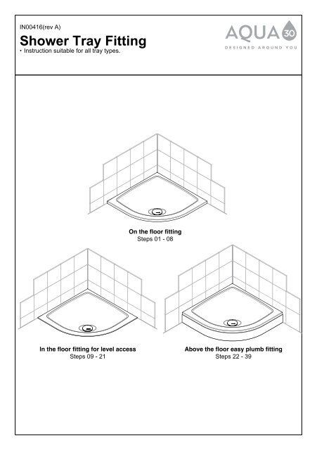
IN00416(rev A)<br />
<strong>Shower</strong> <strong>Tray</strong> <strong>Fitting</strong><br />
• Instruction suitable for all tray types.<br />
In the floor fitting for level access<br />
Steps 09 - 21<br />
On the floor fitting<br />
Steps 01 - 08<br />
Above the floor easy plumb fitting<br />
Steps 22 - 39
Before You Start<br />
• Read the instructions in full before commencing installation.<br />
• Take care of the bottom edges of the tray to avoid chipping of the gelcoat on the corner.<br />
• Check the tray carefully for damage before installation begins. Once installation has begun, the<br />
manufacturer can take no responsibility for damage to the product.<br />
• The tray may be fitted “on the floor” – see steps 1-8, “in the floor” for level access – see steps 9-21 and<br />
“above the floor” for easy plumbing on concrete floors etc. – see steps 22-39. Above the floor fitting<br />
requires the Aqua 30 Top Level Easy Plumb Kit which is available separately.<br />
• Low profile trays require good drainage – ensure that the associated waste pipe runs have a good fall<br />
angle to match the water delivery of the shower unit. We strongly recommend the use of the<br />
Aqua 30 90mm High-Flow Waste, which is available separately.<br />
• Have all the correct tools available – see opposite.<br />
• Ensure that the area is clean, dust free and dry before fitting.<br />
• It is recommended that shower trays are installed before tiling / cladding of the wall surfaces. Ideally the<br />
tile / cladding will overlap the corner radius of the tray such that the mounting surface for the enclosure<br />
will be exactly where the corner radius meets the tray top surface.<br />
During Installation<br />
• Protect the surface of the shower tray with a cloth or cardboard to avoid damage<br />
• In all situations the tray must be bedded on a stiff 5:1 mixture of sand to cement or a ready mixed mortar<br />
product. The void between the underside well surface of the tray and the substrate must be fully filled<br />
to avoid any risk of movement or cracking in use (note that this does not include the space inside the<br />
rim of the tray, which may be left unfilled). Observe the manufacturers recommendations and safety<br />
instructions when handling mortar, particularly with regard to personal protective equipment ie. dust<br />
mask and gloves. Avoid direct skin contact with wet mortar.<br />
• Carefully seal the waste and tray to wall junctions with an anti-fungicidal silicone.<br />
• Wait 24 hours before standing on the tray to ensure that the mortar bed and silicone have fully cured.<br />
Fig.A<br />
Direct Floor Installation:<br />
Refer to Steps 1-8 for<br />
Installation details.<br />
Fig.B<br />
Inset Floor Installation:<br />
Refer to Steps 9 - 21 for<br />
Installation details.<br />
MORTAR BED<br />
SHOWER<br />
TRAY<br />
FLOOR<br />
BOARDS<br />
SHOWER<br />
TRAY<br />
MORTAR BED<br />
FLOOR<br />
BOARDS<br />
PLYWOOD<br />
BOARDS<br />
SILICONE<br />
SILICONE<br />
TILES<br />
TILES<br />
PLASTERBOARD<br />
WALL<br />
PLASTERBOARD<br />
WALL
In-use and care recommendations<br />
• Clean the tray with soapy water and use a soft bristle brush if required for any crevices, then rinse and<br />
dry. Finish off with a soft, clean towel. Avoid all abrasives and harsh detergents.<br />
• If a bath mat is used in the tray, remove after use to avoid any risk of marking.<br />
Safety<br />
• This product may be heavy and require two people to carry and install it.<br />
• When drilling, check first for hidden pipes and cables.<br />
• Use safety eyewear when drilling.<br />
• Observe precautions when handling cement / mortar.<br />
Disclaimer<br />
• Please notify the retailer immediately of any damage or faults. The manufacturer cannot be held<br />
responsible for installation costs that may arise from damaged or faulty product being installed.<br />
• Please dispose of all packaging with due regard for the environment.<br />
Materials required<br />
• 18mm Marine ply, battens and noggins for “in the floor fit” as required.<br />
• Sand and cement or ready-mixed mortar<br />
•<br />
A dedicated high flow waste and easy plumb kit are available separately<br />
Tools Required (not supplied)<br />
Spirit Level Screwdriver Tape Measure Pencil Utility Knife<br />
Junior hacksaw<br />
Silicone Gun & Sealant Power Drill Suitable Hole Saw Bits<br />
Help Line: 0870 241 6131<br />
Jigsaw<br />
Lines open: 8.30am - 5.00pm Monday to Friday<br />
Standard National call charge rate from BT landlines
Parts & <strong>Fitting</strong>s Supplied<br />
!<br />
Keep small parts away from children<br />
<strong>Tray</strong>*<br />
X1<br />
D2<br />
D1<br />
<strong>Tray</strong> (mm)<br />
Legs Clips Joiners<br />
760 & 800 Square 5 8 1<br />
900 Square<br />
5 10 1<br />
1200 x 760, 800 Rectangle<br />
8 10 1<br />
1200 x 900 Rectangle<br />
8 11 1<br />
800, 900 Quadrant<br />
6 6 NA<br />
Please Note:<br />
*Varies depending on tray / kit type.<br />
Top Level Easy Plumb Kit available separately<br />
!<br />
Please notify the retailer immediately<br />
of any damage or faults. The<br />
manufacturer cannot be held<br />
responsible for any installation costs<br />
that may arise from a damaged or<br />
faulty product being installed.<br />
Waste Cover<br />
X1<br />
Waste<br />
Assembly<br />
X1<br />
Board*<br />
X1<br />
Clips<br />
<strong>Tray</strong> Skirt*<br />
X1<br />
High flow waste -<br />
Available<br />
separately<br />
Skirt Joiner<br />
Square & rectangle<br />
trays only<br />
Legs
D1 D2<br />
A No.8 x ¾” Pan Head Pozi Screws<br />
x1<br />
per skirt<br />
(actual size) clip / foot<br />
B<br />
A<br />
B<br />
Washer<br />
Skirt Fixing<br />
Bracket<br />
X4<br />
Loose Screws & <strong>Fitting</strong>s Supplied<br />
A<br />
B<br />
(actual size)<br />
Qty<br />
Qty<br />
x1<br />
per skirt<br />
clip / foot
Direct to Floor (Finished Floor) Fixing Details only:<br />
For Infloor fitting please refer to steps 9-21 & for Easy Plumb 22-39<br />
1<br />
2<br />
!<br />
Position <strong>Tray</strong> and mark<br />
waste position.<br />
!<br />
!<br />
2.1<br />
2.2<br />
Ensure floor boards are sound<br />
and secure - if not board out<br />
area with 18mm marine ply.<br />
Ensure <strong>Tray</strong> is correctly<br />
positioned and level.<br />
Remove floor boards to gain<br />
access to waste pipe and<br />
fit the Waste Trap fitment.<br />
Cut out floor board to suit<br />
waste hole, (as marked in<br />
previous step). Recommended<br />
diameter 140mm.<br />
Ensure waste is not obstructed as<br />
this may cause leakage
3<br />
<strong>Tray</strong> Preparation:<br />
4<br />
Liberally apply silicone sealant to back of tray.<br />
Mix a stiff 5/1 composition of sand and<br />
cement or use ready-mixed prepared to<br />
manufacturers instructions.<br />
Thoroughly mix and spread with high<br />
spots to contact tray underside - ensure<br />
all of the tray well is fully supported.<br />
Ensure <strong>Tray</strong> is correctly<br />
positioned and level.<br />
5 Apply silicone<br />
sealant and PTFE<br />
tape as required.<br />
!<br />
!<br />
Take precautions when handling<br />
cement / mortar.<br />
4.1<br />
!
6<br />
7<br />
5mm<br />
8<br />
5mm<br />
!<br />
!<br />
!<br />
Ensure <strong>Tray</strong> is correctly<br />
positioned and level.<br />
Thoroughly Seal <strong>Tray</strong><br />
to Wall.<br />
Tile down to <strong>Tray</strong><br />
surface leaving a 5mm<br />
gap for sealing.<br />
Ensure Silicone Sealant<br />
thoroughly seals junction of<br />
tiles and tray.<br />
!<br />
Once silicone and mortar<br />
is dry water test the<br />
waste for drainage.
Inset Floor Fixing Details only:<br />
For On the floor fitting please refer to steps 1-8. For easy Plumb 22-39<br />
9<br />
!<br />
10<br />
Cut out tray footprint to the depth<br />
of the floorboards & remove.<br />
Beware of concealed pipework &<br />
electrical cables.<br />
Position tray and mark position<br />
!<br />
11<br />
!<br />
Ensure <strong>Tray</strong> is correctly<br />
positioned.<br />
Check the tops of the joist are<br />
level.
!<br />
12<br />
13<br />
14<br />
18mm<br />
Place battens 18mm from the top of<br />
perimeter noggins & joists.<br />
!<br />
!<br />
12.1<br />
Add noggins as additional support as<br />
required.<br />
13.1<br />
Fit the Waste Trap fitment.<br />
Align waste with tray. Do not drill the<br />
joists as this may compromise their<br />
strength.<br />
14.1<br />
Wall<br />
Wall<br />
Battens<br />
Joists<br />
Floor<br />
Battens<br />
Joists<br />
Floor<br />
Noggins<br />
Plan View<br />
Plan View
15<br />
16<br />
<strong>Tray</strong> Preparation:<br />
17<br />
Liberally apply silicone sealant to back of tray.<br />
!<br />
!<br />
Infill with 18mm marine ply cutting<br />
a hole for the waste. Recommended<br />
diameter 140mm.<br />
Mix a stiff 5/1 composition of sand and<br />
cement or use ready-mixed prepared to<br />
manufacturers instructions.<br />
! Take precautions when handling<br />
!<br />
Thoroughly mix and spread with high<br />
spots to contact tray underside - ensure<br />
all of the tray well is fully supported.<br />
cement / mortar.<br />
17.1<br />
Ensure <strong>Tray</strong> is correctly positioned &<br />
levelled.
18 Apply a silicone<br />
sealant and PTFE<br />
tape as required.<br />
19<br />
!<br />
Ensure tray is correctly<br />
positioned and level.<br />
Thoroughly seal tray to wall.
20 Tile down to tray<br />
surface leaving a 5mm ! gap for sealing.<br />
5mm<br />
21<br />
5mm<br />
!<br />
!<br />
Ensure silicone sealant<br />
thoroughly seals junction<br />
of tiles and tray.<br />
Once silicone and mortar<br />
is dry water test the<br />
waste for drainage.
Easy Plumb <strong>Fitting</strong> Details only:<br />
For On the floor fitting please refer to steps 1-8. For In the floor fitting 9-21<br />
Fig. A: Board layouts and Leg positions are unique to each kit size & type.<br />
It is recommended that the waste is situated at the front of the tray when installed for easy access.<br />
Fig. B: Skirt Layouts<br />
22<br />
!<br />
Quadrant Square<br />
Rectangle<br />
Quadrant Square Rectangle<br />
Square & rectangle boards require a 4mm clearance from the wall.<br />
Quadrant tray boards may butt against the wall.<br />
Offer Board into position.
Adjustable foot preparation<br />
!<br />
23.1<br />
23.2<br />
Locking Key<br />
Foot Body<br />
Foot Base<br />
Please Note: Adjustable<br />
Foot is supplied assembled,<br />
disassemble as shown.<br />
Position Adjustable<br />
Foot base into foot<br />
holes in Board.<br />
Refer to Fig. A for<br />
foot positions.<br />
Mark fixing hole<br />
positions.<br />
23<br />
!<br />
IMPORTANT NOTE:<br />
Ensure board and adjustable foot<br />
bases are correctly positioned.
!<br />
* Drill pilot hole to suit floor type, if<br />
required use wall plugs (not supplied &<br />
if necessary).<br />
24.1* 24.2<br />
25.1<br />
Ensure the waste is not obstructed<br />
as this may cause leakage.<br />
A<br />
B<br />
24<br />
!<br />
25<br />
!<br />
For accuracy fit feet bases in<br />
conjunction with board.<br />
Route waste pipe as required<br />
ensuring foot clearance.
26<br />
!<br />
Screw skirt clips onto underside<br />
of board using holes provided, as<br />
required<br />
Foot Body preparation:<br />
Choose four feet at the<br />
extremities of the board &<br />
set to the high position.<br />
A<br />
B<br />
Set all others at the low position.
27<br />
28<br />
!<br />
27.1<br />
28.1<br />
Position feet into board.<br />
Push hard to ensure foot is fully<br />
located.<br />
Position feet bodies and board into<br />
foot base.
Square & Rectangular boards<br />
!<br />
!<br />
!<br />
29<br />
*<br />
Assemble skirt if required.<br />
Trim with a junior hacksaw at each<br />
end to match the wall.<br />
Skirt Joiner<br />
When using the corner junction use the factory cut ends<br />
at the junction for best finish<br />
Inside view<br />
Ensure skirt snaps securely into<br />
fixing clips.<br />
Work progressively from one end, if the skirt should kink this is due to the board being<br />
slightly out of flat and can be compensated for by final adjustment of the legs.<br />
!
Fig. C: Positioning locking key into ADJUSTABLE POSITION:<br />
30<br />
i)*<br />
* Please Note: Top of foot body is not shown for legibility only.<br />
You do not need to disassemble foot body at this stage.<br />
Locate locking key onto depth stops<br />
on the inside of the leg body so that it<br />
sits in a proud position.<br />
ii)*<br />
!<br />
Ensure that the locking key is set<br />
in a proud position, as shown in<br />
Fig.C (above).
*<br />
31<br />
i)<br />
*<br />
ii)<br />
iii)<br />
Ensure that the tray skirt is clear of<br />
the floor.<br />
Adjustable Foot: Adjustment Details<br />
Twist locking key as required to adjust<br />
board height to suit.<br />
For simple adjustment:<br />
Using the extremity legs only, level the tray from front to back on the one side. Then<br />
level the opposite side. Next level from side to side across the tray. This can be done by<br />
adjusting both legs an equal amount together. Check the skirt clearance whilst proceeding<br />
to get a good flush fit with the floor. If necessary the skirt can be trimmed by scoring with<br />
a sharp knife and breaking along the score line. Finally lower the central legs ensuring the<br />
board is fully level & will bear weight without deflection.
Fig. D: Positioning locking key into FIXED POSITION:<br />
i)*<br />
iii)<br />
* Please Note: Top of foot body is not<br />
shown for legibility only. You do not need<br />
to disassemble foot body at this stage.<br />
Remove locking key and twist around<br />
one detent.<br />
ii)*<br />
Ensure top of locking key lines up with<br />
fixing teeth on foot body.<br />
iv)
33<br />
33<br />
!<br />
!<br />
Ensure that Locking Key is set in<br />
a fixed position, as shown in Fig.D<br />
(on previous page).<br />
Locking key should be flush with<br />
top of the board.<br />
Check fit of tray<br />
& skirt match.<br />
! Remove skirt.<br />
!<br />
Mix a stiff 5/1 composition of sand and<br />
cement or use ready-mixed prepared to<br />
manufacturers instructions.<br />
!<br />
Do not mix cement on board itself to<br />
prevent excess moisture ingress. Take<br />
! precautions when handling cement /<br />
mortar.<br />
Thoroughly mix and spread with high<br />
spots to contact tray underside - ensure<br />
all of the tray well is fully supported.
<strong>Tray</strong> Preparation:<br />
34<br />
Liberally apply silicone sealant to back<br />
of tray. Only apply to the area where<br />
is it positioned against the wall.
35<br />
36<br />
!<br />
Apply a silicone<br />
sealant and PTFE<br />
tape as required.<br />
Ensure tray is correctly<br />
positioned and level.<br />
Thoroughly seal tray<br />
to wall.
37<br />
5mm 5mm<br />
Ensure silicone sealant thoroughly<br />
seals junction of tiles and tray.<br />
5mm 5mm<br />
!<br />
!<br />
Tile down to <strong>Tray</strong> surface leaving a<br />
5mm gap for sealing.<br />
!<br />
Once silicone & mortar is<br />
dry water test the waste<br />
for drainage.
39 Refit skirt & silicone seat skirt to<br />
!<br />
floor, tray & walls for security
Notes: