OVERVIEW OF SRF-RELATED ACTIVITIES AT JEFFERSON LAB
OVERVIEW OF SRF-RELATED ACTIVITIES AT JEFFERSON LAB
OVERVIEW OF SRF-RELATED ACTIVITIES AT JEFFERSON LAB

Create successful ePaper yourself
Turn your PDF publications into a flip-book with our unique Google optimized e-Paper software.
<strong>OVERVIEW</strong> <strong>OF</strong> <strong>SRF</strong>-<strong>REL<strong>AT</strong>ED</strong> <strong>ACTIVITIES</strong> <strong>AT</strong> <strong>JEFFERSON</strong> <strong>LAB</strong> *<br />
Abstract<br />
<strong>SRF</strong>-related activities at JLab are varied and increasing.<br />
Operation of CEBAF at 5.7 GeV for nuclear physics is<br />
now routine. There has been significant progress in the<br />
development and testing of components and subsystems<br />
for a new cryomodule design for coming upgrades of the<br />
JLab CEBAF and FEL. Construction of the first such<br />
module has begun, and further optimization studies<br />
continue. Jefferson Lab joined the collaboration to build<br />
the Spallation Neutron Source (SNS). JLab will contribute<br />
81 cavities in 23 SNS cryomodules. Prototyping of the<br />
beta 0.61 and 0.81 cavities is nearing completion.<br />
Development and testing of the high-power coaxial input<br />
coupler for SNS is underway. Fresh efforts have been<br />
initiated to pursue improved understanding and control of<br />
<strong>SRF</strong> surfaces. JLab has led discussions and development<br />
of modern low-level rf controls tailored for powerefficient<br />
operation of high-gradient <strong>SRF</strong> cavities in lightly<br />
beamloaded, cw applications. To support these efforts,<br />
major upgrades and renovations to the JLab <strong>SRF</strong> facilities<br />
and information infrastructures are underway. The lab has<br />
recognized the importance of <strong>SRF</strong> to future developments<br />
in the accelerator community by the creation of the new<br />
Institute for <strong>SRF</strong> Science and Technology.<br />
1 INTRODUCTION<br />
Jefferson Lab continues to operate the CEBAF<br />
accelerator with its 338 <strong>SRF</strong> cavities toward an aggressive<br />
nuclear physics program. Operation at 5.7 GeV with<br />
polarized electrons is routine. The JLab energy recovering<br />
linac IR FEL has passed the 2 kW cw mark and is gaining<br />
usage as a tool for basic and applied research. The<br />
upgrade of the FEL to produce 10 kW IR is to begin in<br />
2002. JLab is a major partner in the construction of SNS<br />
and is developing controls and fabricating and testing<br />
cavities for the planned RIA facility. The priority given<br />
by the nuclear physics community to the upgrade of<br />
CEBAF to 12 GeV has provided a clear challenge to those<br />
involved with <strong>SRF</strong> work. In addition, the success of the<br />
energy-recovering linac (ERL) concept in the JLab FEL<br />
has stimulated exploration of designs for new light<br />
sources, electron cooling of protons, and high current<br />
electron-ion colliders. JLab has recently joined the<br />
TESLA collaboration and looks forward to being a<br />
partner in future developments. To provide a solid<br />
technical basis to support all of this work, JLab is<br />
_________________________________________<br />
*Work supported by the U.S. Department of Energy, contract<br />
DE-AC05-84ER40150.<br />
† reece@jlab.org<br />
Charles Reece †<br />
Institute for <strong>SRF</strong> Science and Technology<br />
Thomas Jefferson National Accelerator Facility<br />
Newport News, VA 23606, USA<br />
expanding its activities in basic <strong>SRF</strong>-related R&D and has<br />
formed the new Institute for <strong>SRF</strong> Science and Technology<br />
with the mission of expanding the knowledge base in <strong>SRF</strong><br />
and applying that knowledge to future accelerators of all<br />
types.<br />
2 RECENT OPER<strong>AT</strong>ION <strong>OF</strong> CEBAF<br />
2.1 Optimization for physics<br />
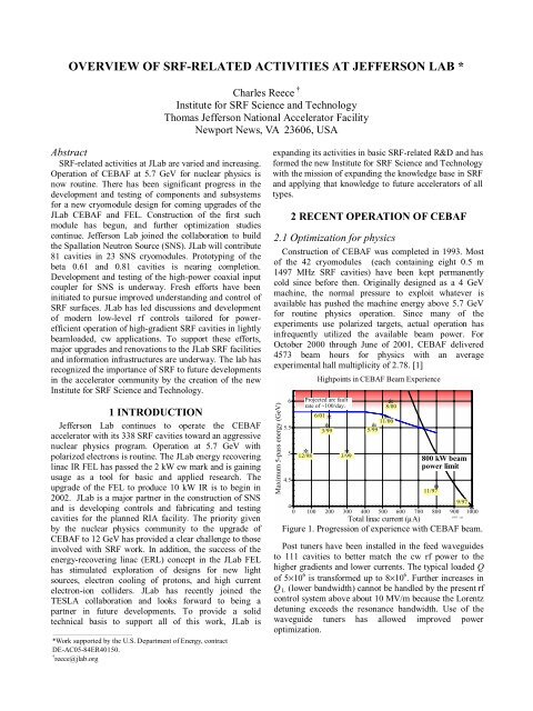
Construction of CEBAF was completed in 1993. Most<br />
of the 42 cryomodules (each containing eight 0.5 m<br />
1497 MHz <strong>SRF</strong> cavities) have been kept permanently<br />
cold since before then. Originally designed as a 4 GeV<br />
machine, the normal pressure to exploit whatever is<br />
available has pushed the machine energy above 5.7 GeV<br />
for routine physics operation. Since many of the<br />
experiments use polarized targets, actual operation has<br />
infrequently utilized the available beam power. For<br />
October 2000 through June of 2001, CEBAF delivered<br />
4573 beam hours for physics with an average<br />
experimental hall multiplicity of 2.78. [1]<br />
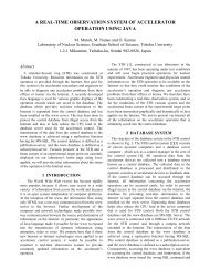
Maximum 5-pass energy (GeV)<br />
6<br />
5.5<br />
5<br />
4.5<br />
∗<br />
Highpoints in CEBAF Beam Experience<br />
Projected arc fault<br />
rate of ~100/day.<br />
6/01<br />
12/98<br />
∗<br />
∗<br />
3/99<br />
∗<br />
3/99<br />
∗<br />
5/99<br />
∗<br />
∗<br />
800 kW beam<br />
power limit<br />
9/97<br />
4<br />
0 100 200 300 400 500 600 700 800 900 1000 ∗<br />
6/01 cer<br />
Total linac current (µA)<br />
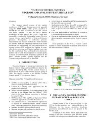
Figure 1. Progression of experience with CEBAF beam.<br />
Post tuners have been installed in the feed waveguides<br />
to 111 cavities to better match the cw rf power to the<br />
higher gradients and lower currents. The typical loaded Q<br />
of 5×10 6 is transformed up to 8×10 6 . Further increases in<br />
Q L (lower bandwidth) cannot be handled by the present rf<br />
controlsystemaboveabout10MV/mbecausetheLorentz<br />
detuning exceeds the resonance bandwidth. Use of the<br />
waveguide tuners has allowed improved power<br />
optimization.<br />
8/00<br />
11/00<br />
∗<br />
11/97
Increasing the prompt waveguide vacuum interlock<br />
from 1×10 -7 to 5×10 -7 eliminated a source of common<br />
trips triggered by rf transients associated with nearby<br />
thunderstorms.<br />
The arcing at the cold ceramic windows persists as the<br />
primary operational limitation on the gradients of the <strong>SRF</strong><br />
cavities. The detailed behavior of this field-emissioninduced<br />
phenomenon is particular to each cavity. The<br />
methods for operational characterization and optimization<br />
have been previously reported.[2] A particular challenge<br />
has been to identify the non-local effects of window arcs<br />
being induced by high-gradient operation of a nearby<br />
cavity.<br />
Cavities<br />
0<br />
<<br />
existing cryomodule warm window assembly using an<br />
indium wire seal. Two cryomodules, one in the FEL and<br />
one in CEBAF slot SL21, have been operating reliably<br />
with similar windows at power levels up to 30 kW.<br />
To reduce the risk of opening another cold helium leak<br />
as in NL11, we are developing a new technique for<br />
changing the warm windows on installed cryomodules<br />
that does not include a full warm-up. To change the warm<br />
window, the waveguide vacuum space must be vented.<br />
The current plan is to vent and purge the waveguide<br />
vacuum space with only helium while maintaining the<br />
cryomodule at ~40 K. At this temperature helium will not<br />
condense and can be pumped out after window exchange.<br />
A test of our ability to maintain a cryomodule in this<br />
temperature range was performed during the May 2001<br />
CEBAF maintenance period. The module was maintained<br />
at an intermediate temperature for several days, but was<br />
accidentally allowed to warm to ~70 K, well above the<br />
target temperature. Additional testing will be required to<br />
qualify the change-out technique. Installation of the first<br />
replacement windows is scheduled for late September<br />
2001.<br />
2.4 Helium processing<br />
Helium processing of the installed cryomodules in<br />
CEBAF has proven quite fruitful, adding ~430 MeV to<br />
the five-pass maximum energy. [4] A perhaps final<br />
reapplication of the developed procedure is being made<br />
during 2001 to the cryomodules processed first. Up to six<br />
cryomodules will receive helium processing during the<br />
September-October maintenance down. An additional<br />
10–20 MV gain is anticipated for the North linac. Higher<br />
power pulsed helium processing is being considered as a<br />
technique for seeking further additional voltage from the<br />
existing cryomodules.<br />
3 FELST<strong>AT</strong>US ANDPLANS<br />
The JLab FEL first produced 1.7 kW cw 3 µm light in<br />
June 1999.[5] Since that time the FEL has been serving a<br />
number of applied and basic research users. The injector<br />
“quarter-cryomodule” and the full cryomodule used for<br />
recirculation continue to operate reliably. The highfrequency<br />
HOMs produced by the intense short bunches<br />
have required the routine masking of the IR window<br />
heating interlock to avoid false trips.[6]<br />
The maximum output power has recently exceeded<br />
2.1 kW, and record-breaking powers at harmonic<br />
frequencies have also been exploited for micromachining<br />
and ablation. An initial test exploring pulsed laser<br />
deposition of niobium films might eventually prove<br />
relevant to <strong>SRF</strong> applications.[7] The energy-recoveringlinac<br />
(ERL) concept demonstrated by the FEL has<br />
attracted significant attention, and is serving to stimulate<br />
exploration of new accelerator applications.<br />
An upgrade of the FEL to 10 kW in the IR is underway,<br />
with an expected completion in 2002.[8] The IR Upgrade<br />
design calls for adding two cryomodules. One of these<br />
cryomodules is presently installed in CEBAF, and the<br />
second is to be a Mk II version of the CEBAF upgrade<br />
design. The three cryomodules are expected to provide<br />
40/40/70 MV, respectively. It is likely that this<br />
implementation will also enable > 1 kW operation of the<br />
FEL in the V-UV to 240 nm. Details are provided by<br />
Merminga’s contribution to this workshop.[9]<br />
JLab intends to pursue previously inaccessible studies<br />
of ultrafast phenomena in condensed matter physics,<br />
atomic physics, chemistry and life sciences. Combining<br />
the recently acquired superconducting synchrotron Helios<br />
with the FEL, JLab will develop a unique capability for<br />
pump/probe experiments.[10]<br />
4 SNS ROLE, PROGRESS, AND PLANS<br />
Since the Santa Fe workshop in 1999, JLab has joined<br />
as a partner lab in the construction of SNS. As part of the<br />
R&D program, we are responsible for developing the beta<br />
0.61 and 0.81 <strong>SRF</strong> cavity designs, including their coaxial<br />
fundamental and HOM couplers, and designing, building<br />
and testing a prototype cryomodule.[11] For the SNS<br />
construction project, we are to provide 23 cryomodules,<br />
11 containing three β=0.61 cavities and 12 containing<br />
four β=0.81 cavities. The accelerating gradients of the<br />
0.61 cavities must exceed 10.1 MV/m; high β cavities<br />
must exceed 12.5 MV/m. These specifications correspond<br />
to peak surface electric fields of 27.5 MV/m. As an SNS<br />
R&D program, JLab will, building from the work of KEK,<br />
develop an electropolishing system and enhanced<br />
contamination control procedures during the construction<br />
of the 0.61 modules in hopes of subsequently increasing<br />
the gradient of the high-β cavities to 15.9 MV/m. JLab is<br />
also providing the cryogenic refrigeration and distribution<br />
system for SNS.<br />
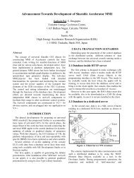
Prototype cavities of both types have been fabricated<br />
and tested at JLab. (See Figure 5.) The prototype coaxial<br />
input coupler design is complete, and two have been<br />
tested to 500 kW.[12] Designs are complete for several<br />
cryomodule subsystems and most major procurements<br />
have been placed, including the cavity production contract.<br />
Testing of the prototype β=0.61 cryomodule is planned<br />
for spring 2002. Production assembly and testing of the<br />
SNS cryomodules is to begin in Summer 2002.<br />
Figure 5. SNS prototype β=0.61 and 0.81 cavities.
5 FUTUREDIRECTIONS<br />
Under the leadership of the new head of the JLab<br />
Accelerator Division, Swapan Chattopadhyay, two new<br />
organizations have been created. The Center for<br />
Advanced Studies of Accelerators, CASA, will pursue<br />
concepts and designs for new accelerator applications.<br />
The Institute for <strong>SRF</strong> Science and Technology, which has<br />
significant overlap with CASA, will develop and provide<br />
<strong>SRF</strong>-based solutions for accelerator needs at JLab and<br />
elsewhere. In addition to design and production<br />
responsibilities for cryomodules, a significant part of the<br />
institute’s mission is <strong>SRF</strong> materials R&D.<br />
Satisfying JLab’s commitment to the SNS construction,<br />
building the IR FEL upgrade, and preparing for the<br />
upgrade of CEBAF to 12 GeV are the principal<br />
production activities for the next few years. The institute<br />
expects to extend and enhance existing collaborative<br />
relationships with other laboratories worldwide. We<br />
anticipate full participation in the design, development,<br />
and production needs for RIA, TESLA, EIC, and nextgeneration<br />
light sources.<br />
6 HIGHLIGHTS<br />
6.1 Upgrade activities to date<br />
During the past several years, cavity and cryomodule<br />
designs have been developed for use in upgrades to<br />
CEBAF and the JLab FEL.[13] Two of these cryomodules<br />
(Mk II) are to be completed in 2002, one for CEBAF and<br />
one for the FEL IR upgrade. Key subsystems are<br />
presently in fabrication and testing.<br />
The cavities for these two cryomodules are of a hybrid<br />
design. They use the same cell shapes as the initial<br />
CEBAF cavities (Mk I), but adding two additional cells<br />
per cavity. The λ/2 stub input coupler is replaced by a λ/4<br />
stub to eliminate the field asymmetry that gives rise to a<br />
transverse “coupler kick” and to reduce the tight<br />
mechanical tolerances required to establish the desired<br />
external Q of the coupler to the cavity. The waveguide<br />
HOM couplers of the Mk I cavity have been replaced with<br />
an adaptation of the DESY couplers developed for<br />
TESLA use. Sixteen of these cavities are presently in<br />
fabrication at JLab. The performance specification for the<br />
cavities in the Mk II cryomodules is average<br />
Eacc=12.2 MV/m, with a Q0 of > 6×10 9 .<br />
The first space frame in which the eight seven-cell<br />
cavities are to be mounted is presently being evaluated.<br />
(See Figure 8.)<br />
The new tuner for the upgrade exceeded the<br />
specification for resolution during its initial evaluation<br />
using the Horizontal Test Bed (HTB).[14] The tuner,<br />
which uses a concentric linear motion scissor-jack<br />
mechanism to place all bearing parts external to the<br />
cryomodule, met the necessary resolution of < 2 Hz using<br />
only the mechanical tuner.[15]<br />
Figure 6. CEBAF Mk II upgrade cavity<br />
Figure 7. Early test of seven-cell upgrade cavity without<br />
couplers, before and after electropolishing.<br />
Figure 8. Upgrade cryomodule space frame and vacuum<br />
vessel.
Since control of microphonics is crucial in this<br />
application, the cavity microphonic response to tuner<br />
actuation was monitored and found to be less than 0.3 Hz<br />
peak. The piezoelectric fine tuner also met or exceeded all<br />
specifications. The frequency response of the whole<br />
system, including the tuner, was also evaluated for<br />
possible dynamic applications such as active vibration<br />
cancellation.<br />
Figure 9. Prototype tuner for CEBAF upgrade.<br />
Initial tests of microphonic sensitivities of the upgrade<br />
cavities were also carried out on the HTB. Although the<br />
mechanical suspension was different than that of upgrade<br />
cryomodules, opportunity was taken to characterize the rf<br />
resonance response of the cavity/cryostat system to<br />
background vibration, swept frequency, pulsed rf, and<br />
external mechanical impulse.[16] The dominant excitation<br />
from background was an ambient vibration at 54.7 Hz.<br />
The most significant mechanical vibration mode of the<br />
structure was observed at 33.7 Hz. The net microphonic<br />
detuning in the HTB was 2.5 Hz rms, which is below the<br />
design limit of 3.5 Hz rms. Similar tests will be made on<br />
the SNS and upgrade cryomodules during the next year.<br />
6.2 New options for CEBAF upgrade<br />
It would take 16 new cryomodules with the<br />
performance specification of the Mk II style to obtain<br />
12 GeV with 5.5 passes through CEBAF.[13] Ten of these<br />
cryomodules would fill presently empty slots, while six<br />
would replace the weakest of the Mk I cryomodules. The<br />
maximum beam current of the 12 GeV design is 465 µA.<br />
A presumption in past plans was that the present CEBAF<br />
klystron design could be pushed to 8 kW by raising the<br />
gun voltage. Events of the past year demonstrated that this<br />
is not an option, and the development of a new gun is<br />
being pursued.<br />
Removal of this constraint on the 12 GeV design and<br />
the stretch-out of the schedule allow further optimization<br />
of the cavities to reduce overall project costs. Exploiting<br />
current design and fabrication methods, we intend to<br />
develop a Mk III cavity for CEBAF that will increase the<br />
shunt impedance and geometry factor while obtaining<br />
state-of-the-art <strong>SRF</strong> performance.<br />
One potential improved cavity design has been<br />
proposed by Barni et al.[17] With it one can construct a<br />
12 GeV CEBAF design that might be realized with only<br />
ten new cryomodules, using 13 kW klystrons.[18] This<br />
design assumes an average cavity gradient of 19.2 MV/m.<br />
An even more ambitious design goal is to realize<br />
25 MV/m in the 0.7 m cavities, while dissipating only<br />
33 W at 2.1 K, using the same klystron. Such a goal could<br />
only be realized by reliably eliminating field emission<br />
sources from the cavity, maintaining surface resistances<br />
of ~25 nΩ, and implementing an agile rf system capable<br />
of handling the Lorentz-force detuning and microphonics.<br />
6.3 SNS cavity prototyping<br />
Under the leadership of P. Kneisel, the design,<br />
fabrication, and testing of the SNS prototype cavities has<br />
proceeded quickly and successfully.[19] With minimal<br />
time available for development, an international<br />
collaborative effort quickly produced initial<br />
electromagnetic and mechanical designs. Design codes<br />
were used to evaluate potential multipacting behavior,<br />
Lorentz-force sensitivities, and microphonic vibrational<br />
modes. The coaxial fundamental coupler was scaled from<br />
the KEK design, and the HOM couplers were scaled from<br />
the DESY design for TESLA.<br />
The SNS cavities are fabricated from niobium with<br />
RRR > 250. The prototype cavities are being built at JLab.<br />
A new 500-ton press was procured to deep-draw the half<br />
cells. The JLab electron beam welder (EBW) is used for<br />
all niobium welding. A new TIG-welding station has been<br />
set up to weld the titanium helium vessel to the NbTi end<br />
dishes.<br />
For details of the SNS cavity designs and test results<br />
see Ciovati’s contribution to this workshop.[20] Figures<br />
10–12 show fabrication, processing, and testing of SNS<br />
cavities.<br />
Figure 10. E-beam an SNS prototype cavity.
Figure 11. Preparation of an SNS cavity for test in the<br />
vertical test area (VTA).<br />
Figure 12. TIG welding of an SNS prototype cavity<br />
helium vessel.<br />
Figure 13. Setting up an SNS medium-beta cavity for<br />
internal chemistry.<br />
Q 0<br />
1.E+11<br />
1.E+10<br />
1.E+09<br />
MB cavity - T=1.96K HB cavity - T=2.09K<br />
MB<br />
Design goal<br />
HB<br />
Design goal<br />
0 1 2 3 4 5 6 7 8 9 10 11 12 13 14 15 16 17 18 19 20<br />
E acc [MV/m]<br />
Figure 14. Test of first beta 0.81 prototype cavity.<br />
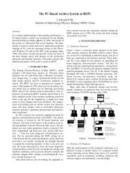
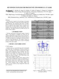
6.4 SNS coupler prototyping<br />
The fundamental power couplers for the SNS <strong>SRF</strong><br />
cavities must support a peak power of 550 kW for a<br />
1.3 ms pulse length at 60 pulses per second. The general<br />
design of the high power coaxial input coupler for the<br />
SNS <strong>SRF</strong> cavities is a geometrical scaling with frequency<br />
from the geometry used for Tristan and KEK-B.[21]<br />
Detailed rf, mechanical, and thermal designs have been<br />
completed satisfactorily. The prototypes were fabricated<br />
at JLab and then conditioned and tested using a high<br />
power klystron at LANL. The first pair of couplers (see<br />
Figure 15) have been operated successfully at 500 kW<br />
after ~32 hours of conditioning. See K. Wilson et al.<br />
contribution to this workshop. [12]<br />
Figure 15. First SNS prototype input couplers.<br />
6.5 SNS cryomodule design<br />
The designs of the two SNS cryomodules [22,23]<br />
borrow from several existing cryomodules already in use<br />
or in planning. Alignment and support of the cavity string<br />
is supported via nitronic rods, as was done in the original<br />
CEBAF Mk I cryomodules. The alignment rods are<br />
attached to a rigid space frame, as is planned for the<br />
CEBAF upgraded cryomodule. The space frame allows<br />
assembly of the cavity string before insertion into the<br />
vacuum vessel.
The end cans, which provide the interface for the<br />
cryogens, are similar to the L shaped ones used in CEBAF.<br />
A 2 K heat exchanger was added to the return end can as<br />
was done in the LHC cryomodules. This allows the<br />
refrigerator to supply 3 bar, 4.5 K gas to the cryomodules<br />
that is split into two streams. One stream goes through the<br />
2 K heat exchanger before going through the JT valve and<br />
producing the superfluid helium used to cool the cavities.<br />
The other stream is controlled by a second JT valve and<br />
used to cool the outer conductor of the coaxial<br />
fundamental power coupler.<br />
The tuner is a scaled version of one designed for use on<br />
the TESLA cryomodules and uses a cold stepper motor<br />
with harmonic drive. A copper thermal shield operating at<br />
40 K is incorporated in the cryomodule, as are two mumetal<br />
shields, one at 2 Kelvin and the other at room<br />
temperature.<br />
6.6 Controls development<br />
Every accelerator application of <strong>SRF</strong> requires a set of rf<br />
controls that meet particular needs. It is clear that a new<br />
control system will be required for the upgrade<br />
cryomodules in CEBAF. The controls needed eventually<br />
for RIA are rather similar. Both applications will employ<br />
high-gradient cavities that are lightly loaded with cw<br />
beam. Interests in rf power economy favor higher external<br />
Q’s, but tuning control assurance and microphonics add<br />
practical constraints. Modern digital technology has some<br />
distinct advantages over analog systems. To help foster a<br />
convergence of the best ideas on this subject, JLab hosted<br />
the Workshop on Low Level RF Controls for<br />
Superconducting Linacs in April 2001. [24] The<br />
workshop was organized by C. Hovater and L. Merminga.<br />
The use of a hybrid system combining an analog selfexcited<br />
loop and implementing digital feedback for phase<br />
and gradient control appears to be very attractive for lowcurrent<br />
cw applications. JLab is developing such a control<br />
system that may serve the needs of both the CEBAF<br />
upgrade and RIA.<br />
6.7 <strong>SRF</strong> R&D<br />
Collaborative R&D work done with DESY and INFN<br />
for TESLA and with MSU for RIA is presented by others<br />
at this workshop.<br />
The DC field emission scanning microscope integrated<br />
with SEM and EDS analysis has been commissioned by<br />
Tong Wang. The system identifies all sites on 2.5 cm<br />
diameter samples that field emit below 100 MV/m.<br />
Systematic comparison of surface preparation techniques<br />
has begun. See reference [25], this workshop.<br />
A vacuum deposition system has been built to test the<br />
idea of energetic condensation of Nb on a copper<br />
substrate. The system directly uses microwave power to<br />
create the pure Nb plasma. A description of the system<br />
and the first Nb films produced are contributed to this<br />
workshop by Genfa Wu.[26]<br />
An exploration of the effectiveness of alternative<br />
electropolishing solutions has recently begun at JLab.<br />
Initial results are presented by A. Wu.[27]<br />
6.8 Facility upgrades<br />
The automated closed chemistry system and high<br />
pressure rinsing station just installed at the time of the last<br />
<strong>SRF</strong> workshop have been fully commissioned and are in<br />
active use. These stations are located within the Class 100<br />
cleanroom. A new electropolishing station is being<br />
prepared in the chemistry area of the cleanroom.<br />
The balance of the cleanroom suite has been<br />
reconfigured to accommodate the clean assembly of<br />
cavity strings. This is in contrast to the assembly of cavity<br />
pairs used for CEBAF Mk I cryomodules. A portion of<br />
the cleanroom has been allocated for cleaning and<br />
assembling the SNS input couplers.<br />
The rf processing and testing of the SNS fundamental<br />
power couplers requires a high power rf source.<br />
Preparations are underway to accommodate a 1 MW<br />
pulsed 805 MHz system to be provided by LANL in<br />
February 2002. This single klystron source will be shared<br />
between the coupler test stand and the cryomodule test<br />
facility (CMTF).<br />
The CMTF in the JLab Test Lab building is being<br />
renovated in preparation for testing SNS and upgrade<br />
cryomodules. The temporary control room and test cave<br />
that were setup in 1989 are being reconfigured into an<br />
arrangement that supports production testing of SNS (and<br />
potentially RIA) cryomodules at 805 MHz using 20 kW<br />
cw and 1 MW sources, as well as upgrade cryomodules<br />
for CEBAF and the FEL with multiple 8 kW klystrons at<br />
1497 MHz. Use of the cryomodule test cave, which<br />
previously housed a synchro-cyclotron, has suffered from<br />
remanent magnetic fields locally as high as 6 G. These<br />
fields saturated the magnetic shielding in cryomodules<br />
and reduced the accessible Q0 values to < 5×10 9 . This<br />
cave has now been outfitted with a large magnetic shield<br />
to reduce the ambient fields to ~0.1 G within the roomsize<br />
volume where cryomodules are tested. (See Figure 16.)<br />
Figure 16. Magnetic shielding being installed in the<br />
CMTF cave.
The cryogenic capacity of the Test Lab facilities is also<br />
being increased from about 4 g/s to 7 g/s liquid helium.<br />
The efficiency of the local plant is being improved and an<br />
additional cold box is being brought online. A new cold<br />
transfer line from the accelerator site will be available as a<br />
backup cryogen source. Controls enhancements will be<br />
made in the distribution of cryogens between the CMTF<br />
and the vertical test area (VTA) with its eight semiindependent<br />
dewars.[28]<br />
Additional facility upgrades that are complete or in<br />
progress include a major controls upgrade for the EBW, a<br />
new furnace for hydrogen degassing of large (SNS)<br />
cavities (Figure 17), an extension and enhancement to the<br />
production ultrapure water system setup of new assembly<br />
lines for SNS and upgrade modules, and automation of an<br />
existing brazing furnace.<br />
Completion and commissioning of SIMS, scanning<br />
Auger, and TEM surface analysis systems are underway.<br />
These systems will play important roles in new <strong>SRF</strong><br />
surface characterization studies.<br />
Figure 17. New 1250°C furnace for hydrogen degassing<br />
of large cavities. (A 700 MHz test cavity is shown in the<br />
hot zone.)<br />
6.9 Pansophy<br />
The institute is implementing a new web-based<br />
information management system. We call it Pansophy.<br />
Pansophy will be our tool for developing, using, and<br />
retaining all procedures, design information, production<br />
travelers, test data, electronic log books, shared databases,<br />
online analysis modules, and scheduling information.<br />
[29] This system is a custom integration of several<br />
commercial software utilities, DocuShare ,<br />
ColdFusion ,<br />
Matlab ,Ingres ,<br />
and common desktop programs. Users<br />
of the system range from process managers, shop-floor<br />
technicians, and test engineers to after-the-fact data<br />
miners and operations staff. The system integrates<br />
important quality assurance elements of procedural<br />
control, automated data accumulation into a secured<br />
central database, prompt and reliable data query and<br />
retrieval, and online analysis tools, all accessed by users<br />
via their platform-independent web browsers.<br />
Cryomodule Production & Testing<br />
- Process<br />
Procedure<br />
- Test<br />
Control<br />
- Process<br />
- Assembly<br />
Data Collection<br />
E-Logbooks<br />
PANSOPHY<br />
Data Query<br />
& Display<br />
Applications<br />
Analysis<br />
Figure 18. Conceptual schematic of the Pansophy system.<br />
The cavity and cryomodule production travelers are the<br />
controlled procedures used to prepare, assemble, and test<br />
parts that become a commissioned cryomodule. These<br />
travelers specify actions to take and data to be acquired<br />
along the way. To efficiently capture the data into a<br />
database, the travelers themselves will be accessed and<br />
used via web browsers. The forms presented to the user<br />
are auto-generated from a custom MSWord template and<br />
directly create the database structure used to collect and<br />
store production data.<br />
Figure 19. Pansophy home page.<br />
One element in the Pansophy system is a web-based<br />
document sharing system, DocuShare ,<br />
which supports<br />
flexible access and revision control, as well as<br />
searchability and reliable backups.
Figure 20. The institute’s DocuShare home page on the<br />
JLab intranet.<br />
7SUMMARY<br />
<strong>SRF</strong> activities at Jefferson Lab are now varied and busy.<br />
Around our core support of the existing and evolving<br />
CEBAF nuclear physics program and basic and applied<br />
FEL programs, the Institute has major commitments to<br />
external collaborations--SNS, and potentially RIA and<br />
TESLA--and is embarking on new missions for education<br />
and key <strong>SRF</strong> materials science research. Significant<br />
infrastructure investments are being made to support the<br />
growing level of activity and to meet the technical<br />
challenges that lie ahead.<br />
8 ACKNOWLEDGMENTS<br />
The vast majority of the work reported here is not the<br />
author’s. It is to the good credit of all the members of the<br />
Institute for <strong>SRF</strong> Science and Technology at JLab, as well<br />
as many members of CASA and the Accelerator<br />
Engineering Department. The future, even more than the<br />
past, will be a highly collaborative one.<br />
9 REFERENCES<br />
[1] S. Suhring, JLab operations, private communication.<br />
[2] J. R. Delayen et al., “Operational Optimization of Large<br />
Scale <strong>SRF</strong> Accelerators,” proceedings of 1999 PAC, pp. 940–<br />
942.<br />
[3] J. F. Benesch and C. E. Reece, "CEBAF's <strong>SRF</strong> Cavity<br />
Manufacturing Experience", Advances In Cryogenic<br />
Engineering, Vol 39, p. 597, ed. P. Kittel (Plenum Press, 1994)<br />
[4] C. E. Reece, “Operating Experience with Super-conducting<br />
Cavities at Jefferson Lab,” Particle Accelerators, Vol. 60, pp.<br />
43–52.<br />
[5] G. R. Neil, et al., PRL 84 662-665 (2000), and<br />
G. Neil, “High Power FELs Driven by RF Superconducting<br />
Linacs,” proceedings of 9 th <strong>SRF</strong> workshop, Santa Fe, pp. 593–<br />
601.<br />
[6] S. Benson, “High Power Free Electron Lasers,” proceedings<br />
of 1999 PAC, pp. 212–216.<br />
[7] Riley and Neil, JLab, private communication.<br />
[8] D. Douglas, “The Jefferson Lab 1kW IR FEL,” proceedings<br />
of LINAC 2000, pp. 716–720.<br />
[9] L. Merminga, these proceedings.<br />
[10] A. Hutton et al., “A Synchronized FEL-Synchrotron<br />
Radiation Facility at Jefferson Lab,” contribution to 2001 PAC.<br />
[11] Y. Cho, these proceedings.<br />
[12] K. Wilson et al., “The Prototype Fundamental Power<br />
Coupler for the Spallation Neutron Source (SNS)<br />
Superconducting Cavities: Design and First Test Results,” these<br />
proceedings.<br />
[13] J. Delayen et al., “Development of a Cryomodule for the<br />
CEBAF Upgrade,” proceedings of 9 th <strong>SRF</strong> workshop, Santa Fe,<br />
pp. 218–223.<br />
[14] I. E. Campisi et al., “CEBAF Upgrade Cryomodule<br />
Component Testing in the Horizontal Test Bed (HTB),”<br />
contributionto2001PAC.<br />
[15] G. Davis et al., “Development and Testing of a Prototype<br />
Tuner for the CEBAF Upgrade Cryomodule,” contribution to<br />
2001 PAC.<br />
[16] G. Davis et al., “Microphonic Testing of the CEBAF<br />
Upgrade 7-Cell Cavity,” contribution to 2001 PAC.<br />
[17]Barnietal.,“An Improved Cavity Design for the CEBAF<br />
Upgrade,” JLab Technote TN01-015.<br />
[18] L. Harwood and C. Reece, “CEBAF at 12 and 25 GeV,”<br />
these proceedings.<br />
[19] G. Ciovati, et al., “Superconducting Prototype Cavities for<br />
the Spallation Neutron Source (SNS) Project,” contribution to<br />
2001 PAC.<br />
[20] G. Ciovati, “Superconducting Prototype Cavities for the<br />
Spallation Neutron Source (SNS) Project,” these proceedings.<br />
[21] I. E. Campisi et al., “The Fundamental Power Coupler<br />
Prototype for the Spallation Neutron Source (SNS)<br />
Superconducting Cavities,” contribution to 2001 PAC.<br />
[22] W. Schneider et al., "Design of the SNS Cryomodule,”<br />
contributionto2001PAC.<br />
[23] E. F. Daly et al., "Spallation Neutron Source Cryomodule<br />
Heat Loads and Thermal Design,” contribution to the Cryogenic<br />
Engineering Conference, Madison, WI, July 2001.<br />
[24] http://www.jlab.org/LLRF/<br />
[25] T. Wang, “DC Field Emission Studies on Niobium,” these<br />
proceedings.<br />
[26] G. Wu, “Energetic Deposition in Vacuum,” these<br />
proceedings.<br />
[27] A. Wu et al., “Alternate Electrolyte Composition for<br />
Electropolishing of Nb Surfaces,” these proceedings.<br />
[28] C. Reece et al., “A Closed Cycle Cryogenic System for<br />
Testing Superconducting RF Cavities,” proceedings of 1991<br />
PAC, pp. 2325–2327.<br />
[29] C. Reece et al., “A System for Managing Critical<br />
Knowledge for Accelerator Subsystems: Pansophy,”<br />
contributionto2001PAC.