Installation Guide - Euphonix
Installation Guide - Euphonix
Installation Guide - Euphonix

Create successful ePaper yourself
Turn your PDF publications into a flip-book with our unique Google optimized e-Paper software.
<strong>Euphonix</strong>, Inc.<br />
220 Portage Ave.<br />
Palo Alto, California 94306<br />
Phone: 650-855-0400<br />
Fax: 650-855-0410<br />
Web: http://www.euphonix.com<br />
e-mail: info@euphonix.com<br />
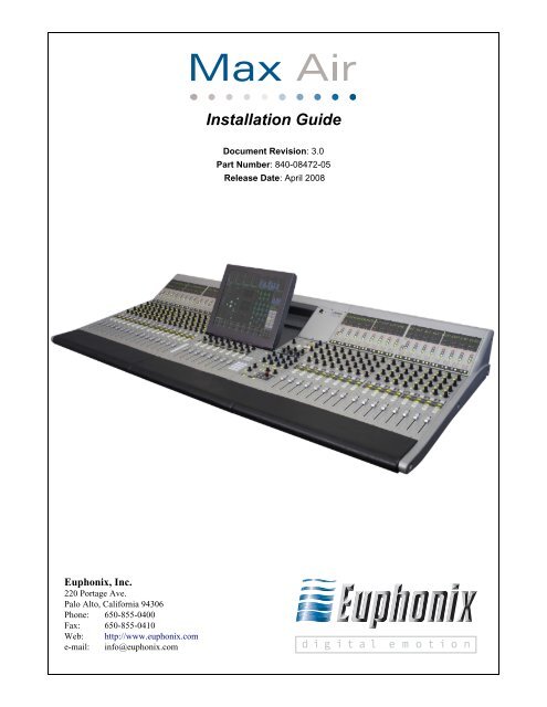
<strong>Installation</strong> <strong>Guide</strong><br />
Document Revision: 3.0<br />
Part Number: 840-08472-05<br />
Release Date: April 2008
In the interest of continued product development, <strong>Euphonix</strong> reserves the right to make improvements<br />
to this manual and the product it describes at any time, without notice or obligation.<br />
System 5, S5, PatchNet, eMix, EuCon, R1, Studio Hub, Audio Deck, Max Air, Reel Feel, Clear<br />
Displays, Track Panner, SnapShot Recall, DSC (Digital Studio Controller), Hyper-Surround,<br />
Total Automation and Mix View are trademarks of <strong>Euphonix</strong>, Inc.<br />
Manual written by Storm Staley, Martin Lucas, Chris Konovaliv, Edward Jones, Rob Wenig,<br />
and Duane Takahashi.<br />
-<br />
©2008 <strong>Euphonix</strong>, Inc. All rights reserved worldwide. No part of this publication may be repro<br />
duced, transmitted, transcribed, stored in a retrieval system, or translated into any language in<br />
any form by any means without written permission from <strong>Euphonix</strong>, Inc.<br />
Note:<br />
This equipment has been tested and found to comply with the limits for a Class A<br />
digital device pursuant to Part 15 of the FCC Rules. These limits are designed to<br />
provide reasonable protection against harmful interference when the equipment is<br />
operated in a commercial environment. This equipment generates, uses, and can<br />
radiate radio frequency energy and, if not installed and used in accordance with -<br />
the instruction manual, may cause harmful interference to radio communications.<br />
Operation of this equipment in a residential area is likely to cause harmful interfer<br />
ence in which case the user will be required to correct the interference at his own<br />
expense.<br />
Caution:Any changes or modifications made by the user that are not expressly approved<br />
by <strong>Euphonix</strong> could void the user’s right to operate the equipment.
1)<br />
2)<br />
3)<br />
4)<br />
5)<br />
6)<br />
IMPORTANT SAFETY INSTRUCTIONS<br />
The lighting flash with arrowhead symbol within an equilateral triangle, is<br />
intended to alert the user to the presence of uninsulated “dangerous voltage”<br />
within the product’s enclosure that may be of sufficient magnitude to constitute a<br />
risk of electrical shock to persons.<br />
The exclamation point within an equilateral triangle, is intended to alert the user<br />
to the presence of important operating and maintenance (servicing) instructions<br />
in the literature accompanying the product.<br />
Read these instructions.<br />
Keep these instructions.<br />
Heed all warnings.<br />
Follow all instructions.<br />
Do not use this apparatus near water.<br />
Clean only with a dry cloth.<br />
7) Do not block any ventilation openings. Install in accordance with the manufacturer’s instructions.<br />
8) Do not install near any heat sources such as radiators, heat registers, stoves, or other apparatus<br />
(including amplifiers) that produce heat.<br />
9) Do not defeat the safety purpose of the polarized or grounding-type plug. A polarized plug<br />
has two blades with one wider than the other. A grounding type plug has two blades and a<br />
third grounding prong. The wider blade or the third prong are provided for your safety. If<br />
the provided plug does not fit into your outlet, consult an electrician for replacement of the<br />
obsolete outlet.<br />
10) Protect the power cord from being walked on or pinched particularly at plugs, convenience<br />
receptacles, and the point where they exit from the apparatus.<br />
11)<br />
Only use attachments/accessories specified by the manufacturer.<br />
12) Use only with the cart, stand, tripod, bracket, or table specified by the manufacturer, or sold<br />
with the apparatus. When a cart is used, use caution when moving the cart/apparatus combination<br />
to avoid injury from tip-over.
13) Unplug this apparatus during lightning storms or when unused for long periods of time.<br />
14) Refer all servicing to qualified service personnel. Servicing is required when the apparatus<br />
has been damaged in any way, such as power-supply cord or plug is damaged, liquid has<br />
been spilled or objects have fallen into the apparatus, the apparatus has been exposed to rain<br />
or moisture, does not operate normally, or has been dropped.<br />
15) WARNING – TO REDUCE THE RISK OF FIRE OR ELECTRIC SHOCK, DO NOT EX-<br />
POSE THIS APPARATUS TO RAIN OR MOISTURE.<br />
16) Do not expose this equipment to dripping or splashing and ensure that no objects filled with<br />
liquids, such as vases, are placed on the equipment.<br />
17) To completely disconnect this equipment from the AC Mains, disconnect the power supply<br />
cord plug from the AC receptacle.<br />
18)<br />
The mains plug of the power supply cord shall remain readily operable.<br />
19) This unit is provided with a power supply cord set suitable for 120V AC input only (for<br />
U.S.A. and Canada). For other than U.S.A. and Canada, a qualified person must provide for<br />
use with this unit, an appropriate, approved power supply cord set which is in compliance<br />
with the end use country requirements and has a minimum cross-sectional area of 1.0mm2.<br />
20)<br />
21)<br />
For units with more than one power cord:<br />
Caution: This unit has more than one power supply cord. Disconnect two power supply<br />
cords before servicing to avoid electrical shock.<br />
Attention: Cet appareil comporte plus d’un cordon d’alimentation. Afin de prévenir les<br />
chocs électriques, débrancher les deux cordons d’alimentation avant de faire<br />
le dépannage.<br />
Operator Accessible Fuse:<br />
Caution: For continued protection against risk of fire, replace only with same type and<br />
rating of fuse.<br />
Attention: Pour ne pas compromettre la protection contre les risques d’incendie, remplacer<br />
par un fusible de même type et de même caractéristiques nominales.
<strong>Euphonix</strong> Max Air <strong>Installation</strong> <strong>Guide</strong><br />
Table of Contents<br />
List of Figures ...................................................................................................................... vii<br />
List of Tables ......................................................................................................................... ix<br />
Chapter 1: Max Air Overview......................................................................................10<br />
1.1 Introduction to Max Air ...........................................................................10<br />
1.2 Digital Signal Processing.........................................................................11<br />
1.3 Analog and Digital I/O.............................................................................11<br />
1.4<br />
1.5<br />
1.6<br />
1.7<br />
1.8<br />
1.9<br />
Microphone Inputs ..................................................................................12<br />
Modular I/O ............................................................................................13<br />
Monitoring ..............................................................................................13<br />
Power ......................................................................................................13<br />
Digital Sync ............................................................................................13<br />
System Control Connections...................................................................14<br />
1.10 Estimating System Requirements ...........................................................15<br />
1.10.1 Number of DF66 DSP Line Cards ............................................15<br />
1.10.2 Number of CM416 16-channel Sections...................................15<br />
1.10.3 I/O Specification .......................................................................15<br />
Chapter 2: Interconnecting System Components..........................................18<br />
2.1 Component Specifications .........................................................................19<br />
2.2 Typical Max Air Room and Equipment Layout ........................................23<br />
2.3 Console Dimensions ..................................................................................24<br />
2.4 Audio Hookup............................................................................................26<br />
2.5 Audio Hookup for Modular I/O.................................................................27<br />
2.6 Synchronization Hookup ...........................................................................28<br />
2.7 Synchronization Details .............................................................................29<br />
2.8 Recommended Digital Sync Generators....................................................30<br />
2.9 Recommended Distribution Amplifiers.....................................................30<br />
2.10 MADI Hookup ...........................................................................................31<br />
2.11 Control Hookup .........................................................................................33<br />
v
<strong>Euphonix</strong> Max Air <strong>Installation</strong> <strong>Guide</strong><br />
Chapter 3: Max Air Components..............................................................................34<br />
3.1 DF66 Super Core ....................................................................................34<br />
3.1.1 Sync Card ...................................................................................36<br />
3.1.2 6 x 6 Bridge Card ................................................................36<br />
3.1.3 SP662 DSP Line Card ................................................................36<br />
3.1.4 SNMP Card ................................................................................37<br />
3.2 Max Air Console....................................................................................38<br />
3.3 SC263 System Computer.......................................................................40<br />
3.4 MC524 Monitor Interface ......................................................................42<br />
3.4.1 Input/Output Connections..........................................................43<br />
3.5 ML530 Mic/Line Interface ....................................................................48<br />
3.6 CO600 Changeover Switch ...................................................................50<br />
3.7 AM713 Analog to MADI Converter......................................................51<br />
3.8 MA703 MADI to Analog Converter......................................................54<br />
3.9 DM714 AES/EBU to MADI Converter.................................................57<br />
3.10 MD704 MADI to AES/EBU Converter.................................................60<br />
3.11 FC726 Format Converter .......................................................................63<br />
3.12 Modular I/O ...........................................................................................69<br />
3.12.1 Modules ...................................................................................70<br />
3.12.2 Frames .....................................................................................73<br />
3.13 TT002 ....................................................................................................76<br />
3.13.1 Input and Output Connections.................................................76<br />
3.13.2 Connection Pinouts (DC-37 GP1 - GP2) .................................77<br />
3.14 FT730 FiberTran Fiberoptic Extender ...................................................78<br />
3.14.1 Rear Panel ...............................................................................79<br />
vi
<strong>Euphonix</strong> Max Air <strong>Installation</strong> <strong>Guide</strong><br />
List of Figures<br />
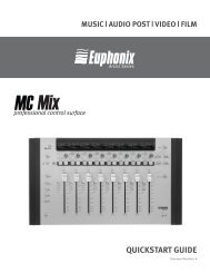
1-1 Typical Console Layout ....................................................................................................10<br />
2-1 Typical Max Air Room and Equipment Layout ...............................................................23<br />
2-2 Max Air Top Dimensions .................................................................................................24<br />
2-3 Max Air Side Dimensions .................................................................................................24<br />
2-4 CM416 Bottom Dimensions .............................................................................................25<br />
2-5 CM404 Bottom Dimensions .............................................................................................25<br />
2-6 Audio Hookup ...................................................................................................................26<br />
2-7 Audio Hookup for Modular I/O ........................................................................................27<br />
2-8 Synchronization Hookup (Word Clock shown, AES/EBU sync may be used) ................28<br />
2-9 Recommended Sync Distribution Method ........................................................................29<br />
2-10 MADI Hookup: one DF66 Core, 1 or >1 DSP Line Cards ................................................31<br />
2-11 MADI Hookup: Primary DF66 Core, CO600 Changeover Switch, Backup DF66 Core ..32<br />
2-12 Control Hookup ................................................................................................................33<br />
3-1 DF66 Super Core Front and Rear Panels ..........................................................................34<br />
3-2 SP662, 6 x 6 Bridge, and Sync Cards ...............................................................................35<br />
3-3 MADI I/O DSP Line Card Cable.......................................................................................36<br />
3-4 16-port BNC Bulkhead Panel ...........................................................................................37<br />
3-5 CM404 Rear Panel ............................................................................................................38<br />
3-6 CM416 Rear Panel ............................................................................................................38<br />
3-7 Ferrite ................................................................................................................................39<br />
3-8 SC263 Front and Rear Panels ...........................................................................................40<br />
3-9 MC524 Front and Rear Panels ..........................................................................................42<br />
3-10 Elco 38 Connector ............................................................................................................43<br />
3-11 Elco 90 Connector ............................................................................................................44<br />
3-12 Elco 90 Connector ............................................................................................................45<br />
3-13 Elco 90 Connector ............................................................................................................46<br />
3-14 DB-25 Connector ..............................................................................................................47<br />
3-15 ML530 Front and Rear Panels .........................................................................................48<br />
vii
<strong>Euphonix</strong> Max Air <strong>Installation</strong> <strong>Guide</strong><br />
3-16 ML530 In 1/In 2 Pinout: Elco 38 Socket .........................................................................49<br />
3-17 ML530 Out 1/Out 2 Pinout: Elco 38 Socket ....................................................................49<br />
3-18 CO600 Changeover Switch ..............................................................................................50<br />
3-19 AM713 Front Panel .........................................................................................................51<br />
3-20 AM713 Rear Panel ...........................................................................................................52<br />
3-21 MA703 Front Panel .........................................................................................................54<br />
3-22 MA703 Rear Panel ...........................................................................................................55<br />
3-23 DM714 Front Panel .........................................................................................................57<br />
3-24 DM714 Rear Panel ...........................................................................................................58<br />
3-25 DM714 Parallel AES/EBU Digital Inputs: Female DB-25 .............................................59<br />
3-26 MD704 Front Panel .........................................................................................................60<br />
3-27 MD704 Rear Panel ...........................................................................................................61<br />
3-28 MD704 Parallel AES/EBU Digital Outputs: Female DB-25 ...........................................62<br />
3-29 FC726 Front and Rear Panels ..........................................................................................63<br />
3-30 Modular I/O Frame Front and Rear Panels ......................................................................69<br />
3-31 Modular I/O Modules .......................................................................................................70<br />
3-32 More Modular I/O Modules .............................................................................................72<br />
3-33 AD914 RJ-45 Pinout ........................................................................................................73<br />
3-34 Modular I/O Stagebox Configuration #1 ..........................................................................74<br />
3-35 Modular I/O Local-Side Interface Configuration #1 ........................................................74<br />
3-36 TT002 Card and Panels ....................................................................................................76<br />
3-37 TT002 P1 Connections and Pinouts .................................................................................76<br />
3-38 Simplified TT002 GPO and GPI circuits .........................................................................78<br />
3-39 FT730 Front Panel ............................................................................................................79<br />
3-40 FT730 Front Panel Status Leds ........................................................................................79<br />
3-41 FT730 Rear Panel ............................................................................................................80<br />
3-42 FT730 Rear Panel Sync Connectors .................................................................................81<br />
3-43 FT730 Internal Sync Input Jumper ...................................................................................81<br />
3-44 FT730 Rear Panel TCC, MADI, and Fiber Connectors ...................................................82<br />
viii
<strong>Euphonix</strong> Max Air <strong>Installation</strong> <strong>Guide</strong><br />
List of Tables<br />
1-1 DF66 Requirements ....................................................................................................... 15<br />
1-2 Summary of <strong>Euphonix</strong> “Classic” MADI Converters ..................................................... 16<br />
1-3 Summary of <strong>Euphonix</strong> Modular I/O .............................................................................. 16<br />
1-4 Summary of Max Air Components ................................................................................ 17<br />
2-1 Max Air Components: Dimensions, Power Consumption, Heat Dissipation ................ 19<br />
2-2 Maximum Cable Lengths ............................................................................................... 20<br />
3-1 In 1 Elco 38 Pinout ........................................................................................................ 43<br />
3-2 In 2 Elco 90 Pinout ........................................................................................................ 44<br />
3-3 Out 1 Elco 90 Pinout ...................................................................................................... 45<br />
3-4 Out 2 Elco 90 Pinout ...................................................................................................... 46<br />
3-5 Out 3 DB-25 Pinout ....................................................................................................... 47<br />
3-6 AES/EBU DB-25 Pinout ............................................................................................... 65<br />
3-7 Common DD-50 Connector Pinout and Usage With Third-party Devices ................... 66<br />
3-8 FC726 TDIF Cable Wiring Specification ...................................................................... 67<br />
3-9 FC726 SDIF Cable Wiring Specification ...................................................................... 68<br />
3-10 I/O Module Summary ..................................................................................................... 75<br />
3-11 Control Module Summary .............................................................................................. 75<br />
3-12 Frame Summary ..............................................................................................................75<br />
3-13 GP1 Inputs and Outputs .................................................................................................. 77<br />
3-14 GP2 Inputs and Outputs .................................................................................................. 77<br />
ix
<strong>Euphonix</strong> Max Air <strong>Installation</strong> <strong>Guide</strong><br />
Chapter 1: Max Air Overview<br />
This chapter explains the basic elements of any digital audio mixing system and introduces<br />
the components of Max Air. It concludes with a section explaining how to estimate your<br />
system’s requirements.<br />
Chapter 2: Interconnecting System Components illustrates how to connect the components,<br />
where to locate them, and lists technical information about the components.<br />
Chapter 3: Max Air Components presents relevant details about each component’s<br />
connectors and cables.<br />
1.1 Introduction to Max Air<br />
The Max Air Console<br />
The Max Air console must contain a CM404 center section module and can have up to three<br />
fully loaded CM416 16-channel Modules, each providing 16 physical faders. The system<br />
can have up to 48 faders, not including the eight faders in the CM404 master section. The<br />
416HL and 416HR, which are half-loaded (left or right) 8-fader modules, can be used to<br />
expand your system.<br />
The following sections discuss important concepts necessary to specify a console layout.<br />
Group<br />
Group<br />
77 88 8<br />
2 33 44 55 66 77 88<br />
1 22 33 44 55 66 77 88<br />
15 15 16<br />
10 11 12 13 14 15 16<br />
9 10 11 12 13 14 15 16<br />
23 23 24<br />
18 19 20 21 22 23 24<br />
17 18 19 20 21 22 23 24<br />
31 31 32<br />
26 27 28 29 30 31 32<br />
25 26 27 28 29 30 31 32<br />
39 39 40<br />
Talkback Mic<br />
34 35 36 37 38 39 40<br />
33 34 35 36 37 38 39 40<br />
47 47 48<br />
42 43 44 45 46 47 48<br />
41 42 43 44 45 46 47 48<br />
Aux<br />
Aux<br />
77 88 8<br />
2 33 44 55 66 77 88<br />
1 22 33 44 55 66 77 88<br />
15 15 16<br />
10 11 12 13 14 15 16<br />
9 10 11 12 13 14 15 16<br />
23 23 24<br />
18 19 20 21 22 23 24<br />
17 18 19 20 21 22 23 24<br />
Mix<br />
Mix<br />
G H<br />
B CC D EE FF G H<br />
A BB CC D EE FF G H<br />
*<br />
*<br />
Inp<br />
Ins Inp<br />
Ins Inp<br />
Dyn<br />
Dyn<br />
Dyn 6<br />
EQ<br />
EQ<br />
EQ<br />
Filt<br />
Filt<br />
Filt<br />
Pan<br />
Aux Pan<br />
Aux Pan<br />
Group roup<br />
Mix Group<br />
Mix Group<br />
Bus<br />
Mix- Bus<br />
Mix- Bus<br />
Oscillator Monitors<br />
On 1<br />
Select<br />
Setup<br />
R W G<br />
Solo<br />
On<br />
On<br />
Control Room<br />
Dim Cut<br />
Setup<br />
Main<br />
Select<br />
Level<br />
Spkrs<br />
Alt 1<br />
Clear<br />
Spkrs<br />
Solo<br />
Alt 2<br />
On<br />
On<br />
Spkrs<br />
R W G<br />
Setup Setup<br />
Dyn<br />
Select 7<br />
Comp<br />
Exp / Gate<br />
Attack Release Depth<br />
Dyn<br />
On5<br />
On<br />
Select<br />
Select<br />
Soft<br />
Knobs<br />
Dyn In In Threshold Ratio<br />
Gain<br />
EQ<br />
Soft oft Knobs<br />
On<br />
On<br />
Paste<br />
Aux<br />
Aux<br />
Copy Paste Paste<br />
All<br />
Masters Sends<br />
Talk<br />
Shelf Low Q Lo Mid Q Hi Mid Q Shelf High Q<br />
Swap<br />
2<br />
Swap Channel 4<br />
Main Channel<br />
Low Freq Lo Mid Freq Hi Mid Freq High Freq<br />
Chan Chan<br />
Chan Chan Chan Chan Chan Chan<br />
Chan<br />
Select Select Select Select Select Select Select Select<br />
Solo<br />
Solo<br />
Solo<br />
Solo<br />
Solo<br />
Solo<br />
Solo<br />
Solo<br />
Solo<br />
Band Low Gain Band Lo Mid Gain Band Hi Mid Gain Band High Gain<br />
On<br />
On<br />
On<br />
On<br />
On<br />
On<br />
On<br />
On<br />
In<br />
In<br />
In<br />
In<br />
On<br />
Select<br />
Select<br />
Select<br />
Select<br />
Select<br />
Select<br />
Select<br />
Select<br />
Insert<br />
M S L<br />
M S L<br />
M S L<br />
M S L<br />
M S L<br />
M S L<br />
M S L<br />
M S L<br />
In<br />
EQ<br />
EQ<br />
Soft<br />
M S L<br />
In<br />
Select<br />
Knobs<br />
Select<br />
Select<br />
Select<br />
Select<br />
Select<br />
Select<br />
Select<br />
Select<br />
Pan<br />
Filters LPF HPF BPF NCH<br />
LPF HPF BPF NCH<br />
Filters<br />
Type Type<br />
Select<br />
12<br />
12<br />
12<br />
12<br />
12<br />
12<br />
12<br />
12<br />
12<br />
48V<br />
48V<br />
48V<br />
48V<br />
48V<br />
48V<br />
48V<br />
48V<br />
CC<br />
7<br />
8 9<br />
Lock ST<br />
Lock ST<br />
Lock ST<br />
Lock ST<br />
Lock ST<br />
Lock ST<br />
Lock ST<br />
Lock ST<br />
Lock<br />
Soft<br />
ST<br />
ST<br />
Mix- 6<br />
Mix- 6<br />
Mix- 6<br />
Mix- 6<br />
Mix- 6<br />
Mix- 6<br />
Mix- 6<br />
Mix- 6<br />
Knobs<br />
Mix-<br />
66<br />
6<br />
In Surround In In Filter 1 In Filter 2<br />
DD<br />
0<br />
0<br />
0<br />
0<br />
0<br />
0<br />
0<br />
0<br />
00<br />
0<br />
4<br />
5<br />
6<br />
LTM<br />
Input<br />
Input A<br />
6<br />
6<br />
6<br />
6<br />
6<br />
6<br />
6<br />
6<br />
66<br />
6<br />
Input B<br />
EE<br />
Input<br />
12<br />
12<br />
12<br />
12<br />
12<br />
12<br />
12<br />
12<br />
RTM A On Hi Z HPF<br />
Select<br />
12<br />
12<br />
1<br />
2<br />
3<br />
clip<br />
clip<br />
clip<br />
clip<br />
clip<br />
clip<br />
clip<br />
clip<br />
clip cli p<br />
clip<br />
FF<br />
18<br />
18<br />
18<br />
18 318<br />
18<br />
18<br />
18<br />
18<br />
18<br />
0<br />
0<br />
0<br />
0<br />
0<br />
0<br />
0<br />
0<br />
00<br />
0<br />
In Front Pan<br />
6<br />
6<br />
6<br />
6<br />
6<br />
6<br />
6<br />
6<br />
B On 48 V<br />
66<br />
6<br />
Balance<br />
Soft<br />
12 3 24<br />
12 3 24<br />
12 3 24<br />
12 3 24<br />
12 3 24<br />
12 3 24<br />
12 3 24<br />
12 3 24<br />
Mic Gain<br />
12 33<br />
Knobs<br />
24<br />
12 3 24<br />
24 6<br />
24 6<br />
24 6<br />
24 6<br />
24 6<br />
24 6<br />
24 6<br />
24 6<br />
GG<br />
Clear 0 Enter<br />
24 66<br />
24 6<br />
Pan Soft<br />
Trim<br />
48 12<br />
48 12<br />
48 12<br />
48 12<br />
48 12<br />
48 12<br />
48 12<br />
48 12<br />
48 12 12<br />
48 12<br />
30<br />
30<br />
30<br />
30<br />
30<br />
30<br />
30<br />
30<br />
Select Knobs<br />
30<br />
30<br />
72 24<br />
72 24<br />
72 24<br />
72 24<br />
72 24<br />
72 24<br />
72 24<br />
72 24<br />
72 24 24<br />
72 24<br />
HH<br />
36<br />
36<br />
36<br />
36<br />
36<br />
36<br />
36<br />
36<br />
Selected<br />
36<br />
36<br />
One Shot<br />
Setup<br />
Setup<br />
42<br />
42<br />
42<br />
42<br />
42<br />
42<br />
42<br />
42<br />
Channel<br />
42<br />
42<br />
48<br />
48<br />
48<br />
48<br />
48<br />
48<br />
48<br />
48<br />
48<br />
48<br />
60<br />
60<br />
60<br />
60<br />
60<br />
60<br />
60<br />
60<br />
60<br />
60<br />
72<br />
72<br />
72<br />
72<br />
72<br />
72<br />
72<br />
72<br />
72<br />
72<br />
Figure 1-1 Typical Console Layout<br />
10<br />
Talk<br />
Swap<br />
Swap Channel<br />
Main Channel<br />
Chan<br />
Select<br />
Solo<br />
On<br />
Select<br />
M S L<br />
Select<br />
8<br />
12<br />
48V<br />
Lock ST<br />
Mix- 6<br />
0<br />
6<br />
12<br />
clip<br />
18<br />
0<br />
6<br />
12 3 24<br />
24 6<br />
48 12<br />
30<br />
72 24<br />
36<br />
42<br />
48<br />
60<br />
72
<strong>Euphonix</strong> Max Air <strong>Installation</strong> <strong>Guide</strong><br />
Max<br />
Air<br />
Overview<br />
Channels<br />
Max Air can have up to 200 channels. Mono channels may be grouped as stereo or any format<br />
up to 7.1, which means that one fader may use one to eight logical channels.<br />
Strips<br />
Each fully loaded CM416 16-channel Module contains 16 physical faders or strips. Each<br />
fader can control two inputs using a Swap button that switches between the Swap and Main<br />
channels.<br />
Layouts<br />
Channels are assigned to strips by using Layouts. Numerous Layouts can be easily stored<br />
and recalled to remap the console surface. To understand Layouts, consider the following<br />
examples:<br />
• A console fitted with one CM416 has 16 physical faders that can control up to<br />
32 channels (Swap and Main per strip). One Layout can assign 32 stereo inputs<br />
to the faders for a total of 64 logical channels.<br />
• The first 32-channels can be assigned and left connected to the mix buses while<br />
a second Layout is recalled. If none of the channels between the Layouts are the<br />
same, there are now 64 logical channels feeding the mix buses at the same time,<br />
although they cannot be controlled simultaneously from the console surface.<br />
Layouts may also be used to place the inputs most often used on the top fader layer, or inputs<br />
that should be grouped together (i.e., microphones or VTRs).<br />
1.2 Digital Signal Processing<br />
The DF66 SuperCore is a rack-mounted unit that performs all Max Air audio processing:<br />
dynamics and EQ, mix buses, record buses, aux sends, and monitor buses. The DF66 DSP<br />
can be allocated, using factory-supplied Mixer Model files, to provide different numbers<br />
of buses and channels for each studio. The number of DF66 DSP cards required in a system<br />
depends on the number of logical channels desired: a mono input uses one logical<br />
channel, a stereo input uses two, and a 7.1 input uses eight.<br />
1.3 Analog and Digital I/O<br />
All audio signals are converted to and from the MADI format through analog and digital<br />
converters, and HD/SD embedders/de-embedders. Up to twenty-four input and twentyfour<br />
output MADI devices are connected to the CO600 Changeover System, which connects<br />
to the DF66 cores.<br />
Analog I/O<br />
All analog signals are converted between analog and MADI formats via the AM713 Ana-<br />
log to MADI Converter, the MA703 MADI to Analog Converter, Modular I/O cards AD920<br />
4ch Analog Line Input, DA921 4ch Analog Line Output, and AD924 4ch Mic Input. The<br />
11
<strong>Euphonix</strong> Max Air <strong>Installation</strong> <strong>Guide</strong> Max Air Overview<br />
The AM713 and MA703 are 24 channel I/O devices with four additional auxilliary channels.<br />
The first two Aux channels are always analog and the remaining two comprise a<br />
digital pair in AES3 and S/PDIF format. Note that one or the other format can be used,<br />
but not both simulataneously. The Modular I/O frame can handle up to 64 signals.<br />
Digital I/O<br />
All digital signals are converted to and from MADI format via the DM714 AES/EBU to<br />
MADI Converter, the MD704 MADI to AES/EBU Converter, and the Modular I/O<br />
DD9xx series AES I/O, input, and output cards. The DM714 and MD704 converters handle<br />
12 AES/EBU pairs (24 channels) of digital audio and four additional auxilliary channels.<br />
The first two Aux channels are always analog and the remaining two comprise a digital<br />
pair in AES3 and S/PDIF format. Note that one or the other format can be used, but<br />
not both simultaneously. All digital inputs of the DM714 have built in Sample Rate Converters.<br />
The Modular I/O frame can handle up to 64 signals. All its digital input cards<br />
have built in Sample Rate Conversion.<br />
Format Conversion<br />
The FC726 is a bidirectional device with 56 channels of sample-rate-converted I/O. In addi-<br />
tion to AES/EBU I/O, the FC726 allows direct connection to several third-party digital<br />
formats. Formats supported by the unit are TDIF, SDIF-2, and ADAT Optical.<br />
AES/EBU outputs are alwasy active even when using third-party formats.<br />
Embedders/De-embedders<br />
The Modular I/O frame can be fitted with cards that can embed or de-embed 4 or 8 channels<br />
of audio to/from a single SD or HD video signal as per the SMPTE272M standard. Audio<br />
from MADI can be embedded to an SD or HD video signal, and audio from an SD or HD<br />
video signal can be de-embedded to MADI. Each Modular I/O frame can handle up to 64<br />
audio channels. An Embedder/De-embedder card cannot embed and de-embed audio simultaneously.<br />
1.4 Microphone Inputs<br />
Microphone inputs are handled by the ML530 Mic/Line Interfaces and Modular I/O re-<br />
preamps. Each ML530 unit contains 24 remote-controlled mic preamps, and is connected<br />
to a deditcated AM713 Analog to MADI Converter. Up to seven ML530s may be connected<br />
in a system.<br />
Each Modular I/O frame can contain from 4 to 32 remote-controlled mic preamps. Up to<br />
seven Modular I/O frames can be deployed in a system.<br />
12
<strong>Euphonix</strong> Max Air <strong>Installation</strong> <strong>Guide</strong><br />
Max<br />
Air<br />
Overview<br />
1.5 Modular I/O<br />
Modular I/O configurations consist of one or more 3RU double-sided frames that can be<br />
fitted with a variety of I/O modules. For interface to the console, all signals are converted<br />
to MADI. Depending on the configuration, a maximum signal density of 64 inputs and 64<br />
outputs can be achieved on a single MADI I/O. Audio formats supported are remote-controlled<br />
preamp, line level analog, AES/EBU, and HD/SD embedder/de-embedder. These<br />
formats can be used simultaeously in the same frame. Refer to the <strong>Euphonix</strong> Modular<br />
Configuration <strong>Guide</strong> for more details and configuration possibilities.<br />
1.6 Monitoring<br />
The MC524 Monitor Controller provides analog monitor outputs. This unit provides Main<br />
(7.1), Alt 1 (5.1), and Alt 2 (stereo) control room monitoring, SLS (7.1), and Cues 1–3<br />
(each stereo) studio monitoring, two talkback preamps, and four listen microphone<br />
preamps. The MC524 is connected to a dedicated MA703 MADI to Analog Converter.<br />
1.7 Power<br />
Some of the Max Air console components have dual power entry connectors for redundant<br />
power supplies. We recommend deriving the two power supplies from different sources to<br />
maximize the failsafe capabilities of the system. The best case is to connect one power supply<br />
to a UPS (Uninturuptable Power Supply) and the other to a clean technical power<br />
source. If a UPS is not used, the power supplies should be connected to seperately protected<br />
clean technical power circuits.<br />
1.8 Digital Sync<br />
A high quality digital sync source is required for the Max Air console. Some facilities may<br />
already have a digital master clock or house reference in place but others may require one.<br />
<strong>Euphonix</strong> has tested several digital sync generators and distribution amplifiers and can supply<br />
these devices with the console. Contact a <strong>Euphonix</strong> sales representative for further information.<br />
We recommend following these guidelines:<br />
• It is important to minimize the timing differences between signal paths to avoid<br />
cumulative timing errors. It is good system engineering practice to send sync<br />
signals to all system components from one source.<br />
• Sync signals should not be looped and each distribution amplifier should be fed<br />
directly from the master clock source.<br />
• Drawings in this installation guide show the use of Word Clock. The user may<br />
use either AES/EBU sync (DARS) or Word Clock.<br />
13
<strong>Euphonix</strong> Max Air <strong>Installation</strong> <strong>Guide</strong> Max Air Overview<br />
1.9 System Control Connections<br />
Ethernet<br />
Several intelligent system components are connected via RJ45 Ethernet through a EuCon<br />
Ethernet switch. These devices include:<br />
KVM Extender<br />
The KVM Extender cable is a Category 5 UTP cable, however it does not carry Ethernet<br />
data like the system components. The KVM Extender requires its own dedicated cable. Its<br />
maximum length is 400 ft (120 m).<br />
Monitor, trackball, and keyboard<br />
The Max Air System Computer is displayed on the CM404 touchscreen. A keyboard and<br />
mouse are connected to the CM404. Additionally, a connection for a “local” keyboard,<br />
mouse, video and serial (touchscreen) port is provided at the KVM’s transmitter side (closest<br />
to the SC263) to facilitate local control, i.e., from the Central Equipment Room.<br />
TCC Control<br />
The SC263 System Computer connects to the MC524 Monitor Interface and up to seven<br />
Monitor Interface ML530 Mic/Line Interfaces via a TCC connection.<br />
GPIO Control<br />
• SC263 System Computer<br />
• CM404 Center Section Module<br />
• CM416 16-channel Modules<br />
• DF66 SuperCores<br />
• CO600 Changeover Switch<br />
• Modular I/O Remote Preamps/Embedder/De-embedders (optional)<br />
The TT002 provides GPIO control for the system. This interface is installed in the SC263<br />
System Computer.<br />
14
<strong>Euphonix</strong> Max Air <strong>Installation</strong> <strong>Guide</strong><br />
Max<br />
Air<br />
Overview<br />
1.10 Estimating System Requirements<br />
This section helps estimate the system requirements for a particular installation. Contact a<br />
<strong>Euphonix</strong> representative for an exact specification. Use the following categories to determine<br />
the Max Air components necessary for your studio. Most of the studio details considered<br />
here are relevant to any digital mixing system.<br />
1.10.1 Number of DF66 DSP Line Cards<br />
Some examples of Mixer Models and their relationship to the number of DF66 cards are<br />
shown below.<br />
Number<br />
of cards<br />
Sample<br />
Rate<br />
Table 1-1 DF66 Requirements<br />
Logical<br />
Channels<br />
Record<br />
Buses<br />
NOTE: Table 1-2 refers to logical audio channels not inputs. See Inputs on page xx<br />
to see how to count logical channels based on the number and type of inputs.<br />
1.10.2 Number of CM416 16-channel Sections<br />
One application may require a small, powerful console to control many inputs from a small<br />
number of faders. Other applications may trade console size for the power of accessing<br />
each input quickly without having to swap the fader or recall a Layout. Specify enough<br />
physical faders to conveniently control the required number of inputs, remembering that<br />
multi-channel sources (Stereo, 5.1) can be controlled with a single fader on the Max Air<br />
and do not require 2 or 6 individual faders. There can be up to three fully loaded<br />
CM416s yielding 48 faders, which gives you 96 locations (Main and Swap layer) to<br />
place sources without having to change layouts.<br />
15<br />
Mix<br />
Buses<br />
Aux<br />
Sends<br />
2 48 kHz 68 16 16<br />
8<br />
3 48 kHz 86 24 24 16<br />
3 48 kHz 96 24 24 16<br />
4 48 kHz 130 24 24 16<br />
5 48 kHz 150 24 32 24<br />
6 48 kHz<br />
194 24 32 24<br />
1.10.3 I/O Specification<br />
Bus<br />
Processors<br />
The following tables summarize the I/O capabilities of the <strong>Euphonix</strong> MADI converters.<br />
The number of available MADI I/O ports on the DF66 depends on the number of SP662<br />
DSP cards. Each SP662 provides four MADI I/O ports for a maximum of 24 MADI in-<br />
8<br />
12<br />
0<br />
12<br />
16<br />
16
<strong>Euphonix</strong> Max Air <strong>Installation</strong> <strong>Guide</strong> Max Air Overview<br />
puts and 23 MADI outputs (note: MADI out 1 is reserved for the MA703/MC524 moni-<br />
tor connection).<br />
In the case of Modular I/O, only mic, analog, AES, and embedder/de-embedder modules<br />
are shown. Refer to the <strong>Euphonix</strong> Modular I/O Configuration <strong>Guide</strong> for more details on<br />
sync, MADI I/O, and remote control modules as well as general requirements.<br />
Table 1-2 Summary of <strong>Euphonix</strong> “Classic” MADI Converters<br />
Table 1-3 Summary of <strong>Euphonix</strong> Modular I/O<br />
16
<strong>Euphonix</strong> Max Air <strong>Installation</strong> <strong>Guide</strong><br />
Max<br />
Air<br />
Overview<br />
The following chart summarizes this section:<br />
CM404<br />
CM416<br />
Table 1-4 Summary of Max Air Components<br />
Component Function Number Notes<br />
SC263<br />
System Computer<br />
TT002<br />
GP Input/Output<br />
System<br />
MC524<br />
Monitor Interface<br />
ML530<br />
Mic/Line Interface<br />
DF66<br />
SuperCore<br />
Contains 8 faders for masters, 17-inch Touchscreen,<br />
and Superchannel controls.<br />
Contains 16 physical faders that control two<br />
layers of 16 inputs.<br />
Master<br />
system<br />
computer.<br />
Configures DF66,<br />
controls MC524, ML530, and Modular I/O<br />
components.<br />
Provides up to 32 buffered TTL inputs and 32<br />
open-collector outputs<br />
17<br />
1 required<br />
(max)<br />
3 full max<br />
1 required<br />
Analog monitor output controller 1 required<br />
24 remote-control microphone preamps 7 max<br />
Performs all system DSP<br />
1 required<br />
(2 max in<br />
redundant<br />
system)<br />
Ethernet device<br />
Ethernet device<br />
Ethernet<br />
device.<br />
Connects to MC524<br />
and up to 7 ML530s via TCC.<br />
Houses GPIO card.<br />
Housed in the SC263 System<br />
Computer.<br />
TCC connection to SC263.<br />
1 MA703 is required (included).<br />
TCC connection to SC263. 1 AM713<br />
is required per ML530 (included).<br />
Ethernet device. Requires digital<br />
sync reference.<br />
CO600<br />
Changeover Switch MADI routing hub for failover system. 1 max Ethernet device.<br />
AM713<br />
Analog to MADI<br />
Converter<br />
MA703<br />
MADI to Analog<br />
Converter<br />
DM714<br />
AES/EBU to MADI<br />
Converter<br />
MD704<br />
MADI to AES/EBU<br />
Converter<br />
FC726<br />
Digital Format<br />
Converter<br />
Modular I/O<br />
Provides 24 Analog to MADI Converters, dualchannel<br />
Aux Digital Input (AES/EBU or S/PDIF<br />
available), and Aux dual-channel Analog Input.<br />
Provides 24 MADI to Analog Converters, dualchannel<br />
Aux Digital Output (AES/EBU or S/PDIF<br />
available), and Aux dual-channel Analog Output.<br />
Provides 12 pairs (24 channels) of AES/EBU to<br />
MADI conversion, dual-channel Aux Digital Input<br />
(AES/EBU or S/PDIF available), and Aux dual-<br />
channel Analog Input.<br />
Provides 12 pairs (24 channels) of MADI to<br />
AES/EBU conversion, dual-channel Aux Digital<br />
Output (AES/EBU or S/PDIF available), and<br />
Aux dual-channel Analog Output.<br />
Provides 28 pairs (56 channels) of input format<br />
conversion and 28 pairs (56 channels) of output<br />
format conversion. Supports MADI, AES/EBU,<br />
T-DIF, ADAT Optical, and S-DIF2.<br />
Provides 64 channels of format converted inputs<br />
and outputs. Supports MADI, AES/EBU, Analog,<br />
remote-control mic preamps, HD/SD embedders/de-embedders.<br />
1 required<br />
Paired with<br />
ML530 for<br />
Mic level<br />
inputs.<br />
Paired with<br />
MC524 for<br />
Monitor<br />
outputs.<br />
Optional<br />
Optional<br />
Requires digital sync reference.<br />
Requires digital sync reference.<br />
Optional Requires digital sync reference.<br />
Optional<br />
Requires digital sync reference.<br />
Optional 75-ohm BNC AES/EBU<br />
connectors.<br />
Requires digital sync reference.<br />
Optional 75-ohm BNC AES/EBU<br />
connectors.<br />
Requires digital sync reference and<br />
ethernet connection for remote mic<br />
preamps and 8 ch embedder/deembedder.
<strong>Euphonix</strong> Max Air <strong>Installation</strong> <strong>Guide</strong><br />
Chapter 2: Interconnecting System<br />
Components<br />
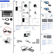
This chapter summarizes technical information for Max Air’s components, including size,<br />
weight, power consumption, cooling, and shows their interconnections. To plan an installaion,<br />
examine Figure 2-1 to learn about suggested equipment locations. The Sync, MADI,<br />
and Control hookup diagrams (Figure 2-7 through Figure 2-11) all show maximum cable<br />
distances.<br />
18
<strong>Euphonix</strong> Max Air <strong>Installation</strong> Guid e Interconnecting<br />
System Components<br />
2.1 Component Specifications<br />
Table 2-1 Max Air Components: Dimensions, Power Consumption, Heat Dissipation<br />
CM404<br />
CM416<br />
CM416HL<br />
CM416HR<br />
MC524<br />
Monitor Interface<br />
ML530<br />
Mic/Line Interface<br />
SC263<br />
System Computer<br />
DF66<br />
SuperCore<br />
Component Height Width Depth Weight<br />
CO600<br />
Changeover Switch<br />
AM713<br />
Analog to MADI Converter<br />
MA703<br />
MADI to Analog Converter<br />
DM714<br />
AES/EBU to MADI Converter<br />
MD704<br />
MADI to AES/EBU Converter<br />
FC726<br />
Digital Format Converter<br />
Modular I/O frame<br />
Various Formats Converter<br />
8.4 in<br />
21 cm<br />
8.4 in<br />
21 cm<br />
8.4 in<br />
21 cm<br />
8.4 in<br />
21 cm<br />
22.3 in<br />
57 cm<br />
24.3 in<br />
62 cm<br />
24.3 in<br />
62 cm<br />
24.3 in<br />
62 cm<br />
19<br />
35.4 in<br />
90 cm<br />
33.5 in<br />
84 cm<br />
33.5 in<br />
84 cm<br />
33.5 in<br />
84 cm<br />
69 lb<br />
32 kg<br />
82 lb<br />
37 kg<br />
71 lb<br />
33 kg<br />
71 lb<br />
33 kg<br />
Typical Power<br />
Consumption<br />
PSU 1: 50 W<br />
PSU 2: 50 W<br />
PSU 1: 50 W<br />
PSU 2: 50 W<br />
PSU 1: 50 W<br />
PSU 2: 50 W<br />
PSU 1: 50 W<br />
PSU 2: 50 W<br />
3.5 in<br />
89 mm<br />
2RU<br />
17 in/432 mm<br />
(19 in/483 mm<br />
faceplate)<br />
18.5 in<br />
470 mm<br />
17 lb<br />
7.7 kg<br />
3.5 in<br />
89 mm<br />
2RU<br />
17 in/432 mm<br />
(19 in/483 mm<br />
faceplate)<br />
18.5 in<br />
470 mm<br />
17 lb<br />
7.7 kg<br />
7 in<br />
177 mm<br />
4RU<br />
(19 in/483 mm<br />
19 in<br />
483 mm<br />
4 lb<br />
20 kg<br />
7 in<br />
177 mm<br />
4RU<br />
(19 in/483 mm<br />
19 in<br />
483 mm<br />
4 lb<br />
20 kg<br />
3.5 in<br />
89 mm<br />
2RU<br />
17 in432 mm<br />
(19 in/483 mm<br />
faceplate)<br />
11.7 in<br />
296 mm<br />
18.7 lb<br />
8.5 kg<br />
3.5 in<br />
89 mm<br />
2RU<br />
17 in/432 mm<br />
(19 in/483 mm<br />
faceplate)<br />
18.5 in<br />
470 mm<br />
17 lb<br />
7.7 kg<br />
2RU 3.5 in<br />
89 mm<br />
17 in/432 mm<br />
(19 in/483 mm<br />
faceplate)<br />
18.5 in<br />
470 mm<br />
17 lb<br />
7.7 kg<br />
2RU 3.5 in<br />
89 mm<br />
17 in/432 mm<br />
(19 in/483 mm<br />
faceplate)<br />
18.5 in<br />
470 mm<br />
17 lb<br />
7.7 kg<br />
2RU 3.5 in<br />
89 mm<br />
17 in/432 mm<br />
(19 in/483 mm<br />
faceplate)<br />
18.5 in<br />
470 mm<br />
17 lb<br />
7.7 kg<br />
2RU 3.5 in<br />
89 mm<br />
17 in/432 mm<br />
(19 in/483 mm<br />
faceplate)<br />
18.5 in<br />
470 mm<br />
13.5 lb<br />
6 kg<br />
5.25 in<br />
133.5 mm<br />
3RU<br />
17 in/432 mm<br />
(19 in/483 mm<br />
faceplate)<br />
16.5 in<br />
420 mm<br />
~12 lb<br />
~5.3 kg<br />
80 W (see page<br />
75 for individual<br />
card specs)<br />
Heat<br />
Dissipation<br />
520 BTU/hr<br />
600 BTU/hr<br />
520 BTU/hr<br />
520 BTU/hr<br />
97 W 240 BTU/hr<br />
86 W 345 BTU/hr<br />
200 W 685 BTU/hr<br />
500 W 1025 BTU/hr<br />
100 W 345BTU/hr<br />
54 W 175 BTU/hr<br />
50 W 175 BTU/hr<br />
25 W 90 BTU/hr<br />
18 W 90 BTU/hr<br />
50 W 175 BTU/hr<br />
275 BTU/hr
<strong>Euphonix</strong> Max Air <strong>Installation</strong> <strong>Guide</strong> Interconnecting System Components<br />
Table 2-2 Maximum Cable Lengths<br />
Cable Type Maximum Length<br />
MADI 164 ft / 50 m<br />
Ethernet 300 ft / 91.4 m<br />
TCC 750 ft / 225 m<br />
Sync (WC) 164 ft / 50 m<br />
Sync (AES) 328 ft / 100 m<br />
KVM 500 ft / 150 m<br />
NOTE: If your installation requires a longer cable, contact <strong>Euphonix</strong> Sales for<br />
selecting a variety of fiber-optic solutions.<br />
NOTE: It is the responsibility of the system designers, system integrators, and<br />
end users to assure that the choice of cabling, termination, equalizations, etc.<br />
conform to the recommended practice. Although maximum recommended<br />
distances over copper can be extended with the use of high performance components<br />
(including cables), it is not <strong>Euphonix</strong>’s intention to endorse any particular<br />
brand or method of achieving the end result.<br />
Facility Power Quality Recommendations<br />
Although a detailed exploration into the types of power quality issues is beyond the scope<br />
of this manual, we'd like to briefly touch on a few of the most important mechanisms that<br />
determine your facility's power quality. The following is a list of facility power<br />
standards/specifications that is recommended for optimal and reliable performance of<br />
your <strong>Euphonix</strong> console:<br />
Harmonic Distortion<br />
IEEE Standard 519, Recommended Practices and Requirements for Harmonic Control In<br />
Electrical Power Systems, establishes harmonic limits on voltages for computers and<br />
computer-based equipment. AC power sources shall have no more than a 5% harmonic<br />
voltage distortion factor, with the largest single harmonic being no more than 3% of the<br />
fundamental voltage. Higher levels of harmonics can result in erratic behavior and<br />
unpredictable performance.<br />
Ground resistance is the resistance due to the resistivity of the soil in the vicinity of the<br />
grounding electrode. Most computer equipment manufacturers recommend a maximum<br />
ground resistance of two ohms.<br />
20
<strong>Euphonix</strong> Max Air <strong>Installation</strong> <strong>Guide</strong> Interconnecting System Components<br />
Transients<br />
A two-year study by the IEEE of 200 locations found that over 80% of the equipment<br />
interruptions were due to transients on the power lines. A transient impulse is a sharp,<br />
sudden rise in voltage. The power can jump up to a few thousand volts. The spikes may<br />
contain enough energy to damage sensitive electronic equipment. Transient disturbances<br />
may also cause computers to reset and/or breakers to trip. Spike durations usually last<br />
between 4 microseconds and 1 cycle (17mS at 60Hz) and exceed 50% or greater than the<br />
nominal voltage level.<br />
<strong>Euphonix</strong>'s products have been tested and found to comply with the performance limits of<br />
EN55103:2, E-4 Environment. Should the product be operated in a degraded power<br />
environment, care should be taken to insure that the EN55102 electronic limits are not<br />
exceeded.<br />
Voltage Fluctuation<br />
Voltage fluctuation is a sudden and noticeable change in rms voltage level. It is usually<br />
caused by changing, complex system loads. It is recognized that certain types of electical<br />
and electronic equipment are susceptible to voltage fluctuations. "Flicker", or "light<br />
flicker" is a type of voltage fluctuation. The typical duration is from 3 to 10 cycles, or 50<br />
to 167 milliseconds at 60Hz.<br />
<strong>Euphonix</strong>'s products have been tested and found to comply with the performance limits of<br />
EN55103:2, E-4 Environment. Should the product be operated in a degraded power<br />
environment, care should be taken to insure that the EN55102 EFT limits are not<br />
exceeded.<br />
Voltage Sag<br />
Short-duration undervoltages are called "voltage sags" or "voltage dips". A voltage sag<br />
below 90% of the equipment rating exceeds the minimum allowable standard.<br />
<strong>Euphonix</strong>'s products have been tested and found to comply with the performance limits of<br />
EN55103:2, E-4 Environment. Should the product be operated in a degraded power<br />
environment, care should be taken to insure that the EN55102 Voltage Dips and Interrupt<br />
limits are not exceeded.<br />
Grounding<br />
Ground leakage currents should be 0.0035A or less.<br />
There should only be one neutral-ground bond, at the main service entrance (except in the<br />
case of a separately derived system, i.e., an isolation transformer). The neutral-to-ground<br />
voltage in a 120V, single phase system, is recommended to be less than 3 Vrms. In<br />
high-availability systems, a neutral-to-ground voltage above 0.5 volts has been identified<br />
as a possible source of disturbances.<br />
21
<strong>Euphonix</strong> Max Air <strong>Installation</strong> <strong>Guide</strong> Interconnecting System Components<br />
Uninterruptible Power Supply<br />
These devices are designed to provide continuous power to a load, even with an<br />
interruption or loss of utility supply power. Since the power on an on-line UPS flows<br />
through a rectifier and inverter before reaching the load, most power disturbances are<br />
eliminated through constant filtering. Therefore, an on-line UPS is a good idea for all<br />
High-Availability Systems that cannot guarantee high-quality power. Many UPS' have a<br />
voltage regulator to compensate for voltage variances.<br />
NOTE: If it is determined that your facility is below standard in any of the<br />
specifications described above, contacting an experienced electrician (or<br />
engineering consultant for large facilities) with expertise in power quality<br />
issues is recommended.<br />
22
<strong>Euphonix</strong> Max Air <strong>Installation</strong> Guid e Interconnecting<br />
System Components<br />
2.2 Typical Max Air Room and Equipment Layout<br />
Studio<br />
Control Room<br />
Optional<br />
Studio I/O<br />
Mic-Line IF<br />
AM713 A/D Converter<br />
Analog IF & Patch<br />
Digital IF & Patch<br />
Cue Feeds (from Mon IF)<br />
Listen Mics (to Mon IF)<br />
Control Surface<br />
17<br />
16<br />
15<br />
14<br />
13<br />
12<br />
11<br />
10<br />
9<br />
8<br />
7<br />
6<br />
5<br />
4<br />
3<br />
2<br />
1<br />
0<br />
Talk Mic (to Mon IF)<br />
Console Umbilical (Eucon)<br />
Leave Open<br />
EuCon Switch<br />
SC263 (System PC)<br />
DF66<br />
Primary<br />
CO600 (Changeover Switch )<br />
DF66<br />
Redundant<br />
Leave Open<br />
Figure 2-1 Typical Max Air Room and Equipment Layout<br />
23<br />
Machine Room<br />
Digital Frame<br />
IF Control<br />
MADI<br />
Sync<br />
EuCon Switch<br />
SC263 System Computer<br />
CO600 Changeover Switch<br />
DF66 SuperCores<br />
Machine<br />
Room I/O<br />
AM713 A/D Converter<br />
DM714 AES/EBU-to-MADI IF<br />
FC726 Format Converter<br />
Modular I/O<br />
MC524 Monitor IF & Patch<br />
MA703 Monitor D/A Converter
<strong>Euphonix</strong> Max Air <strong>Installation</strong> <strong>Guide</strong> Interconnecting System Components<br />
2.3 Console Dimensions<br />
29.58<br />
29.58<br />
0.00<br />
5.85<br />
0.00<br />
16.15<br />
22.30<br />
35.43<br />
0.00<br />
1.0 1.0<br />
28.50<br />
75.00°<br />
22.42<br />
20.83<br />
Figure 2-2 Max Air Top Dimensions<br />
CM404 BALANCE POINT<br />
CM416 BALANCE POINT<br />
11.42<br />
9.83<br />
Figure 2-3 Max Air Side Dimensions<br />
24<br />
16.13<br />
15.625<br />
0.00<br />
Dimensions in inches<br />
0<br />
4.39<br />
24.30<br />
5.85<br />
16.25<br />
8.39<br />
6.78<br />
3.06<br />
2.06<br />
1.20<br />
0
<strong>Euphonix</strong> Max Air <strong>Installation</strong> Guid e Interconnecting<br />
System Components<br />
0<br />
.900<br />
23.400<br />
24.300<br />
22.42<br />
20.83<br />
22.42<br />
20.83<br />
Figure 2-4 CM416 Bottom Dimensions<br />
1/4-20 THREADED<br />
INSERT 8 PLACES<br />
1/4-20 THREADED<br />
INSERT 8 PLACES<br />
11.42<br />
9.83<br />
Figure 2-5 CM404 Bottom Dimensions<br />
11.42<br />
25<br />
9.83<br />
8.742<br />
8.742<br />
KEEP CLEAR FOR<br />
VENTILATION<br />
KEEP CLEAR FOR<br />
VENTILATION<br />
KEEP CLEAR<br />
FOR PROPER<br />
VENTILATION<br />
.53<br />
0<br />
0<br />
.53<br />
0<br />
.90<br />
1.79<br />
19.46<br />
21.40<br />
22.30<br />
0<br />
.902<br />
11.723<br />
12.827<br />
23.648<br />
24.300
<strong>Euphonix</strong> Max Air <strong>Installation</strong> <strong>Guide</strong> Interconnecting System Components<br />
2.4 Audio Hookup<br />
Microphone<br />
Studi o<br />
Mic Lines<br />
1-48<br />
Devices requiring<br />
format conversion<br />
1-56 In<br />
1-56 Out<br />
48 Analog<br />
Digital I/O<br />
AES/EBU<br />
Device Inputs<br />
1-48<br />
AES/EBU<br />
Device Outputs<br />
1-48<br />
Analog I/O<br />
Analog<br />
Device Inputs<br />
1-48<br />
Analog<br />
Device Outputs<br />
1-48<br />
ML530<br />
ML530<br />
Mic Line Interface<br />
48 channels (24 AES/EBU pairs)<br />
48 channels (24 AES/EBU pairs)<br />
48 Analog<br />
48 Analog<br />
Monitoring<br />
Control Room<br />
Main Monitors (7.1)<br />
Alt 1Monitors (5.1)<br />
Alt 2Monitors (stereo)<br />
Studio<br />
Mon A - SLS (7.1)<br />
Mon B - Cue 1 (stereo)<br />
Mon C - Cue 2 (stereo)<br />
Mon D - Cue 3 (stereo)<br />
OUTPUTS INPUTS<br />
1-12<br />
13-24<br />
OUTPUTS INPUTS<br />
1-12<br />
13-24<br />
Cabling dependant on device type<br />
Upper 25-48 Lower 25-48 Upper 1-24 Lower 1-24<br />
Patchbay (Optional)<br />
Upper 25-48 Lower 25-48 Upper 1-24 Lower 1-24<br />
Patchbay (Optional)<br />
Figure 2-6 Audio Hookup<br />
26<br />
48 Analog<br />
48 Analog<br />
48 Analog<br />
48 Analog<br />
Monitor Interface<br />
38 Analog<br />
(Mc524<br />
Outs 1&2)<br />
8 Analog (MC524 Out 3)<br />
6 Analog<br />
(MC524 In 1)<br />
Upper 25-48 Lower 25-48 Upper 1-24 Lower 1-24<br />
Patchbay<br />
30 Analog<br />
Console<br />
Talkback<br />
MC524<br />
6 Analog<br />
OUT 1<br />
Producers<br />
Talkback<br />
OUT 2<br />
OUT 3<br />
IN 1<br />
Studio<br />
Listen<br />
Mics (4)<br />
IN 2<br />
8 Analog<br />
AM713<br />
AM713<br />
Analog to MADI<br />
MD704<br />
MD704<br />
MADI to AES/EBU<br />
DM714<br />
DM714<br />
AES/EBU to MADI<br />
FC726<br />
FORMAT CONVERTER<br />
MA703<br />
MA703<br />
MADI to Analog<br />
AM713<br />
AM713<br />
Analog to MADI<br />
2 Analog<br />
(Talkback feed to AM713 Aux Analog In)<br />
24 Analog<br />
MA703<br />
(MC524 In 2)<br />
Talkback<br />
Mic Preamp<br />
Outs (2)<br />
Listen Mic<br />
Preamp<br />
Outs (4)<br />
Solo Bus<br />
Out (stereo)<br />
MADI to Analog<br />
Talkback<br />
Mic Preamp<br />
Outs (2)<br />
Listen Mic<br />
Preamp<br />
Outs (4)<br />
Solo Bus<br />
Out (stereo)<br />
NOTE : MA703, MD704, AM713, and DM714 converters have extra pairs of auxilliary<br />
AES/EBU and analog channels available. See page 51.
<strong>Euphonix</strong> Max Air <strong>Installation</strong> <strong>Guide</strong><br />
2.5 Audio Hookup for Modular I/O<br />
Microphone<br />
Studio<br />
Mic Lines<br />
4~56<br />
4~56 Analog<br />
Digital I/O<br />
AES/EBU<br />
Device Inputs<br />
4~64<br />
AES/EBU<br />
Device Outputs<br />
4-64<br />
HD/SD Embedding/<br />
De-embedding<br />
4~64In<br />
4~64Out<br />
Analog I/O<br />
Analog<br />
Device Inputs<br />
4~64<br />
Analog<br />
Device Outputs<br />
4~64<br />
4~64 channels (2~32 AES/EBU pairs)<br />
4~64 channels (2~32 AES/EBU pairs)<br />
4~64 channels (1~8 HD/SD signals)<br />
4~64 channels (1~8 HD/SD signals)<br />
4~64 Analog<br />
4~64 Analog<br />
Figure 2-7 Audio Hookup for Modular I/O<br />
27<br />
Interconnecting System Components<br />
Mic Line Interface Analog to MADI<br />
MADI to AES/EBU<br />
AES/EBU to MADI<br />
De-embedded audio to MADI<br />
MADI to embedded audio<br />
MADI to Analog<br />
Analog to MADI<br />
NOTE: Different Modular I/O audio formats can share the same frame.<br />
PSU #1 PSU #2 #2<br />
PSU #1 PSU #2<br />
PSU #1 PSU #2<br />
PSU #1 PSU #2<br />
PSU #1 PSU #2
<strong>Euphonix</strong> Max Air <strong>Installation</strong> <strong>Guide</strong><br />
2.6 Synchronization Hookup<br />
Maximum Cable Distances:<br />
Word: 165 ft (50 m)<br />
Alternate Sync Distances:<br />
AES 110 ohm: 328 ft (100m)<br />
AES 75 ohm: 3281 ft (1000m)<br />
House<br />
Video<br />
Studio<br />
W/C In<br />
W/C In<br />
Studio Master Clock<br />
MC524<br />
OUT 1<br />
Monitor Interface<br />
Mic Line Interface<br />
OUT 2<br />
ML530<br />
ML530<br />
Word Clock<br />
Distribution<br />
Amplifier<br />
CO600 Changeover Switch<br />
DF66 SuperCore 1<br />
DF66 SuperCore 1A<br />
OUT 3<br />
Machine Room<br />
IN 1<br />
SYNC<br />
Lock<br />
75<br />
AES In<br />
110<br />
AES In<br />
75<br />
Word In<br />
75<br />
Word Out<br />
SYNC<br />
Lock<br />
75<br />
AES In<br />
110<br />
AES In<br />
75<br />
Word In<br />
75<br />
Word Out<br />
IN 2<br />
OUTPUTS INPUTS<br />
1-12<br />
13-24<br />
OUTPUTS INPUTS<br />
1-12<br />
MADI<br />
I/O<br />
MADI<br />
I/O<br />
MADI<br />
I/O<br />
MADI<br />
I/O<br />
MADI<br />
I/O<br />
13-24<br />
MADI<br />
I/O<br />
MADI<br />
I/O<br />
MADI<br />
I/O<br />
MADI<br />
I/O<br />
MADI<br />
I/O<br />
MADI<br />
I/O<br />
MADI<br />
I/O<br />
Figure 2-8 Synchronization Hookup<br />
28<br />
W/C In<br />
W/C In<br />
W/C In<br />
W/C In<br />
W/C In<br />
W/C In<br />
W/C In<br />
W/C In<br />
W/C In<br />
W/C In<br />
W/C In<br />
W/C In<br />
W/C In<br />
Interconnecting System Components<br />
Modular I/O<br />
AM713<br />
AM713<br />
Analog to MADI<br />
FC727<br />
Format Converter<br />
MD704<br />
MD704<br />
MADI to AES/EBU<br />
MA703<br />
MA703<br />
MADI to Analog<br />
DM714<br />
DM714<br />
AES/EBU to MADI<br />
AM713<br />
AM713<br />
Analog to MADI<br />
MA703<br />
MADI to Analog<br />
Modular I/O<br />
PSU #1 PSU #2<br />
PSU #1 PSU #2
<strong>Euphonix</strong> Max Air <strong>Installation</strong> <strong>Guide</strong> Interconnecting System Components<br />
2.7 Synchronization Details<br />
It is important to minimize the timing differences between signal paths to avoid cumulative<br />
timing errors. It is good system engineering practice to send all system components their<br />
sync signals from one source. Sync signals should not be looped and each distribution amplifier<br />
should be fed directly from the master clock source. The following guidelines are<br />
provided to illustrate the correct sync distribution. Word clock or AES/EBU sync may be<br />
used but word clock is preferred due to its lower cabling and labor costs.<br />
Studios with Existing Digital Master Clock and Sync Distribution<br />
• Clock jitter should be less than 0.025 UI (AES3-1992 (r1997)).<br />
• One additional D/A output is required for each system component.<br />
• Cable runs from the master clock to the distribution amps should be equal in<br />
length (AES11-1997, 5.4).<br />
<strong>Installation</strong>s Without an Existing Digital Master Clock<br />
• Use one of the <strong>Euphonix</strong> recommended sync generators (see next page).<br />
• These sync generators may be set to internal or gen-locked to a video reference.<br />
• Use a <strong>Euphonix</strong> recommended distribution amp (see next page) to feed all system<br />
components and additional studio devices directly.<br />
• Cable runs from the master clock to the distribution amps should be equal in<br />
length (AES11-1997, 5.4)<br />
Equal cable lengths<br />
<strong>Euphonix</strong><br />
Recommended<br />
Sync Generator<br />
Distribution<br />
Amplifier<br />
Distribution<br />
Amplifier<br />
Figure 2-9 Recommended Sync Distribution Method<br />
29<br />
<strong>Euphonix</strong><br />
Console<br />
Components<br />
Studio<br />
Devices
<strong>Euphonix</strong> Max Air <strong>Installation</strong> Guid e Interconnecting<br />
System Components<br />
System Components That Require Digital Sync<br />
• DF66 Supercores<br />
• AM713 Analog to MADI Converters<br />
• MA703 MADI to Analog Converters<br />
• DM714 AES to MADI Converters<br />
• MD704 MADI to AES Converters<br />
• FC726 Format Converters<br />
2.8 Recommended Digital Sync Generators<br />
Lucid<br />
NVision<br />
Apogee<br />
• SSG192: Greatest number of features, most user friendly<br />
• SG4410: Convenient modular design, no pull up/down rates<br />
2.9 Recommended Distribution Amplifiers<br />
NVision<br />
Lucid<br />
• Modular I/O<br />
• Big Ben:<br />
Convenient modular design, six word clock outputs<br />
• DA4010: AES/EBU<br />
• DA4023: Word Clock (48kHz only)<br />
• AESx4 AES/EBU<br />
• CLKx6 Word Clock<br />
30
<strong>Euphonix</strong> Max Air <strong>Installation</strong> <strong>Guide</strong><br />
2.10 MADI Hookup<br />
One DF66 with >1<br />
DSP Line Cards<br />
MA703 MADI to Analog<br />
Converter for MC524<br />
Monitor Interface<br />
DF66 with 1 DSP<br />
Line Card<br />
DF66<br />
MADI Inputs<br />
A<br />
B<br />
C<br />
D<br />
MADI Outputs<br />
A<br />
B<br />
C<br />
D<br />
card 1 card 2<br />
SP662 Line DSP Cards<br />
DF66<br />
MADI Inputs<br />
A<br />
B<br />
C<br />
D<br />
MADI Outputs<br />
A<br />
B<br />
C<br />
D<br />
SP662<br />
DSP Line<br />
Card<br />
MA703 MADI to Analog<br />
Converter for MC524<br />
Monitor Interface<br />
Source Destination<br />
MADI Outputs<br />
Figure 2-10: MADI hookup: one DF66 core, 1 or >1 DSP Line Cards.<br />
31<br />
Interconnecting System Components<br />
MADI Inputs<br />
Source MADI Outputs Destination MADI Inputs<br />
up to 16<br />
more<br />
Source<br />
outputs ..........<br />
MADI Inputs<br />
.........<br />
MADI Outputs<br />
.........<br />
up to 4<br />
more cards<br />
Maximum MADI<br />
Cable Distance: 165 ft (50m)<br />
up to 16 more<br />
Destination<br />
.......... inputs
<strong>Euphonix</strong> Max Air <strong>Installation</strong> <strong>Guide</strong><br />
MADI Hookup<br />
32<br />
Interconnecting System Components<br />
Figure 2-11: MADI hookup: primary DF66 SuperCore, CO600 Changeover Switch, backup DF66 SuperCore<br />
NOTE: It is the responsibility of the system designers, system integrators, and end<br />
users to assure that the choice of cabling, terminations, equalizations, etc. conform<br />
to the recommended practice. Although maximum recommended distances<br />
over copper can be exceeded with the use of high performance components<br />
(including cables), it is not <strong>Euphonix</strong>'s intention to endorse any particular<br />
brand or method of achieving the end result.
<strong>Euphonix</strong> Max Air <strong>Installation</strong> <strong>Guide</strong><br />
2.11 Control Hookup<br />
Ethernet Switch<br />
Max Air Ethernet Cable Harness<br />
Ethernet<br />
System Computer<br />
SC264<br />
Ethernet<br />
TCC Extension<br />
KVM<br />
Switch<br />
Modular I/O<br />
TCC Main Port<br />
PSU #1 PSU #2<br />
KVM<br />
Up to six additional Mic/Line<br />
Interfaces<br />
Figure 2-12 Control Hookup<br />
33<br />
ML530<br />
MC524<br />
OUT 1<br />
OUT 2<br />
OUT<br />
3<br />
Interconnecting System Components<br />
OUTPUTS INPUTS<br />
1-12<br />
13-24<br />
Mic/Line Interface<br />
Lock<br />
75<br />
AES In<br />
110<br />
AES In<br />
75<br />
Word In<br />
75<br />
Word Out<br />
MADI<br />
I/O<br />
IN 1<br />
MADI<br />
I/O<br />
MADI<br />
I/O<br />
IN 2<br />
Monitor Interface<br />
SYNC<br />
MADI<br />
I/O<br />
MADI<br />
I/O<br />
MADI<br />
I/O<br />
Changeover Switch<br />
SYNC<br />
Lock<br />
75<br />
AES In<br />
110<br />
AES In<br />
75<br />
Word In<br />
75<br />
Word Out<br />
MADI<br />
I/O<br />
MADI<br />
I/O<br />
MADI<br />
I/O<br />
MADI<br />
I/O<br />
MADI<br />
I/O<br />
MADI<br />
I/O<br />
DF66 #1<br />
Maximum Distances<br />
Ethernet: 91.4m (300ft)<br />
TCC Control: 228.6 m (750ft)<br />
KVM: 152.4m (500ft)<br />
Machine<br />
Room<br />
DF66 #1-A<br />
Control<br />
Room
<strong>Euphonix</strong> Max Air <strong>Installation</strong> <strong>Guide</strong><br />
Chapter 3: Max Air Components<br />
This chapter discusses the Max Air components and all connectors necessary for operation.<br />
Pinouts for user-wired connections are shown for each component, along with the cables<br />
and connectors provided by <strong>Euphonix</strong>.<br />
3.1 DF66 SuperCore<br />
The DF66 contains three main types of cards: SP662 DSP Line Card, Bridge Card (there are<br />
five types of Bridge Cards) and Sync Card (all cards shown in Figure 3-2).<br />
Power Connectors (IEC): Accepts standard IEC power cords (provided). Two autoranging<br />
switching supplies accept voltages between 100–240 VAC, 50–60 Hz.<br />
Please see the DF66 Super Core Service Manual for an overview of its components.<br />
Figure 3-1 DF66 Super Core Front and Rear Panels<br />
34
<strong>Euphonix</strong> Max Air <strong>Installation</strong> <strong>Guide</strong> System 5 Components<br />
Figure 3-2 SP662, 6x6 Bridge, and Sync Cards<br />
35
<strong>Euphonix</strong> Max Air <strong>Installation</strong> <strong>Guide</strong><br />
3.1.1 Sync Card<br />
36<br />
System 5 Components<br />
AES Sync In (BNC): The DF66 SuperCore clocks to the signal at this port when the<br />
sync source is set to AES Sync. Connect this port to a digital sync reference.<br />
AES Sync In (3-pin Lemo Female): The DF66 SuperCore clocks to the signal at this<br />
port when the sync source is set to AES Sync. Connect this port to a digital sync reference.<br />
Word In (BNC): The DF66 clocks to the signal at this port when the sync source is set to<br />
Word Clock. Connect this port to a digital sync reference.<br />
Word Out (BNC): This signal is active regardless of selected sync source.<br />
3.1.2 Bridge Card<br />
Bridge Cards are used to connect (or bridge) multiple SP662 DSP Line Cards in a DF66.<br />
They mount on top of the SP662 cards. The Bridge Card shown in Figure 3.2 is a 6x6 (for<br />
bridging six SP662 cards). Other types of Bridge Cards are 2x2, 3x3, 4x4, and 5x5.<br />
3.1.3 SP662 DSP Line Card<br />
MADI In (4) and MADI Out (4) digital audio ins and outs on a Combination D (Combo<br />
D) Subminiature connector. A MADI I/O DSP Line Card Cable connects to this Combo<br />
D connector and transports the MADI I/O to eight BNC connectors. See the MADI<br />
Hookup diagram (figure 2-9) and the MADI I/O DSP Line Card Cable diagram (figure<br />
3-3) for details on these connections.<br />
Figure 3-3<br />
MADI I/O DSP Line Card Cable<br />
An optional 16-port BNC Bulkhead Panel (see figure 3-4) allows BNC panel access to the<br />
DSP cards’ MADI ports.
<strong>Euphonix</strong><br />
Max<br />
Air<br />
3.1.4 SNMP Card<br />
<strong>Installation</strong><br />
<strong>Guide</strong><br />
Figure 3-4<br />
16-port BNC Bulkhead Panel<br />
37<br />
Max<br />
Air<br />
Components<br />
An SNMP (Simple Network Management Protocol) card is installed in each DF66 and<br />
System Computer. The SNMP card is a platform-independent server and PC-system<br />
management controller that can detect basic system operating conditions and notify the<br />
user when the conditions fall outside the defined limits. It supports multiple communication<br />
protocols via an RJ-45 ethernet port and an RS232 serial port.
<strong>Euphonix</strong><br />
Max<br />
Air<br />
<strong>Installation</strong><br />
<strong>Guide</strong><br />
3.2 Max Air Console<br />
<br />
<br />
<br />
INTERNAL<br />
TALKBACK MIC EXTERNAL<br />
TALKBACK MIC<br />
TO KVM<br />
EXTENDER<br />
<br />
<br />
MOUSE<br />
KEYBOARD<br />
SERVICE SERIAL 1 SERIAL 2<br />
<br />
<br />
Figure 3-5 CM404 Rear Panel<br />
<br />
LAN<br />
T 5.0 AH<br />
250 V<br />
Caution:<br />
To prevent risk<br />
of fire, replace<br />
fuse with the<br />
same type and<br />
rating.<br />
~100-240V<br />
AC<br />
50-60 Hz<br />
250 Watts<br />
I<br />
O<br />
Figure 3-6 CM416 Rear Panel<br />
38<br />
Max<br />
Air<br />
Components<br />
The Max Air Console consists of several modular components: the CM416 with 16 physical<br />
faders and controls, and the CM404 center section. Each component has the following<br />
connections:<br />
SERVICE<br />
SERIAL 1<br />
SERIAL 2<br />
LAN<br />
CM404<br />
<br />
AC IN 1 AC IN 2<br />
I<br />
O<br />
<br />
T 5.0 AH<br />
250 V<br />
Caution:<br />
To prevent risk<br />
of fire, replace<br />
fuse with the<br />
same type and<br />
rating.<br />
~100-240V<br />
AC<br />
50-60 Hz<br />
250 Watts<br />
AC IN 1 AC IN 2<br />
<br />
Power Connectors (IEC): Accepts two standard IEC power cords (provided). Two autoranging<br />
switching supplies accept voltages between 100–240 VAC, 50–60 Hz.<br />
LAN Port (RJ45): Connect to EuCon Network Switch via RJ45 through the console<br />
Ethernet harness (provided).<br />
If the provided cable harness is not used, install a ferrite at the console end of the cable<br />
at each RJ45 connector. Pass the cable through ferrite three times with two loops. Cover<br />
with heat shrink tubing to protect the cable.<br />
<br />
<br />
T 5.0 AH<br />
250 V<br />
Caution:<br />
To prevent risk<br />
of fire, replace<br />
fuse with the<br />
same type and<br />
rating.<br />
~100-240V<br />
AC<br />
50-60 Hz<br />
250 Watts<br />
CM416<br />
I<br />
I<br />
O<br />
O
<strong>Euphonix</strong> Max Air <strong>Installation</strong> <strong>Guide</strong> Max Air Components<br />
<br />
<br />
<br />
<br />
<br />
Ferrite is available from FerriShield Inc., 212-268-4020, www.ferrishield.com.<br />
Part number: 28B1020-1<br />
Figure 3-7 Ferrite<br />
To KVM Extender (RJ45): Connect to KVM extender (CM404 only).<br />
Talkback (XLR): Connect to the internal and external talkback microphones.<br />
Keyboard and Mouse (PS2): Connect to the keyboard and mouse or trackball.<br />
Serial 1, 2 (DB9): RS232 serial ports (for service only).<br />
Service (DB15HD, PS2): VGA video and keyboard connection (for service only).<br />
39<br />
2.0"
<strong>Euphonix</strong> Max Air <strong>Installation</strong> <strong>Guide</strong> System 5 Components<br />
3.3 SC263 System Computer<br />
Figure 3-8 SC263 Front and Rear Panels<br />
VGA Connector (DA-15): Main video monitor connection.<br />
Keyboard (PS/2): Main keyboard connection.<br />
Mouse (PS/2): Main trackball connection.<br />
Serial Port 1 (DE-9): Com1; touchscreen control connection. (Com2 is wired internally<br />
to the SNMP board’s Com port.)<br />
Serial Port 2 (DE-9): Com3; currently not used.<br />
Serial Port 3 (DE-9): Com4; can be used to connect to external router/control systems.<br />
LAN Port 1 (Onboard RJ45): Connect to EuCon Network Switch via RJ45 (provided).<br />
LAN Port 2 (Auxilary RJ45): Optional connection for external network.<br />
SNMP<br />
LAN Port (RJ45): Connect this port to a network with SNMP monitoring or e-<br />
mail services to enable the hardware monitoring system to report errors.<br />
USB Ports: Connect the USB MIDI Interface to one of these ports. Connect a USB<br />
memory device to one of these ports for file backup, application installations or updates.<br />
11<br />
11<br />
14<br />
<br />
<br />
<br />
<br />
Power Connectors (IEC): Accepts two standard IEC power cords (provided). Two autoranging<br />
switching supplies accept voltages between 100–240 VAC, 50–60 Hz.<br />
12 TCC Main Port (DC-62): Connect TCC breakout cable (provided) to this port. This<br />
cable breaks out to four DA-15 connectors that provide control hookup for the MC524<br />
Monitor Interface and three ML530 Mic/Line Interfaces.<br />
40<br />
<br />
<br />
<br />
17 <br />
12 13<br />
15<br />
16
<strong>Euphonix</strong> Max Air <strong>Installation</strong> <strong>Guide</strong><br />
41<br />
System 5 Components<br />
13 TCC Extension Port (DC-62, optional): Connect a second TCC breakout cable to this port<br />
to connect up to four additional ML530 Mic/Line Interfaces.<br />
14 SNMP Serial Port (DE-9): This port is used to configure the SNMP card via another<br />
computer.<br />
15<br />
16<br />
17<br />
TT002 (75-ohm BNC, DE-9 female, DE-9 male): BNC port is for Bi/Tri-Level Video<br />
input; DE-9 female is for RS422 (Sony 9-pin); DE-9 male is for Midi Machine Control<br />
and Time Code I/O (via breakout cable).<br />
GPIO Port 1 (DC-37): GP Inputs and Outputs 1 to 16.<br />
GPIO Port 2 (DC-37): GP Inputs and Outputs 17 to 32.<br />
Connect the machine room KVM extender (transmitter end) to the VGA, keyboard, and<br />
mouse connectors to the rear panel of the SC263. A second KVM extender (receiver end)<br />
should be installed at the control surface, close to where the Emix monitor, keyboard and<br />
mouse are to be located. The KVM extenders are connected by a single CAT5 cable built<br />
into the console ethernet harness (provided).<br />
NOTE: SC263 rear connector configurations are subject to change.
<strong>Euphonix</strong> Max Air <strong>Installation</strong> <strong>Guide</strong> Max Air Components<br />
3.4 MC524 Monitor Interface<br />
Power Switch: Powers the unit off/on.<br />
Figure 3-9 MC524 Front and Rear Panels<br />
In 1 (38-pin ELCO): Talk Back, Listen Back and Mic inputs. This connector receives four<br />
stereo listen channels and two stereo talk mic inputs. Signals can be boosted or attenuated.<br />
In a standard patch configuration, input cable fans out to 12 female XLRs, of which 6 are<br />
used.<br />
In 2 (90-pin ELCO): Control Room Buses, Monitor A, B, C, D, and Solo buses inputs. This<br />
connector receives eight Monitor A channels, and two channels each for Monitor B, C, D.<br />
These signals can be attenuated only and are typically fed from the AM713 with an included<br />
cable.<br />
Out 1 (90-pin ELCO): Monitor A, B, C, D Speaker outputs. This connector outputs eight<br />
Control Room channels, eight Monitor A channels, and two channels each for Monitor B,<br />
C, D, and Solo. The output cable fans out to two 38-pin ELCO/Edak connectors for the <strong>Euphonix</strong><br />
Patchbay.<br />
Out 2 (90 pin ELCO): Control Room Speakers, Talk Back and Listen Back Preamp, and<br />
Solo Buses outputs. This connector outputs eight Control Room Main channels, six Control<br />
Room Alt 1 channels, two Control Room Alt 2 channels, four Listen pre, two talk pre and<br />
two Solo channels. The output cable fans out to two 38-pin ELCO/Edak connectors for the<br />
<strong>Euphonix</strong> Patchbay.<br />
Out 3 (female DB25): Talk Back, Listen Back, and Solo Preamp outputs. This connector<br />
outputs four Listen pre, two Talk Back pre and two Solo channels . Output cable fans out<br />
to eight male XLRs.<br />
Control (DB15): Input for digital control signal from System Computer (<strong>Euphonix</strong> TCC<br />
bi-directional serial protocol). All patching, switching, and gain controls are communica-<br />
ted via this connection as well as MC524 IP address.<br />
AC Line In (IEC) and Fuse Tray: Accepts standard IEC power cord (provided). An<br />
autoranging switching supply accepts voltages between 90–250 VAC, 50–60 Hz.<br />
42<br />
MONITOR-COMMS INTERFACE<br />
MC<br />
524
<strong>Euphonix</strong><br />
Max<br />
Air<br />
<strong>Installation</strong><br />
<strong>Guide</strong><br />
3.4.1 Input/Output Connections<br />
Table 3-1 In 1 Elco 38 Pinout<br />
Crk # Designator 24 X 32 High Low Gnd<br />
1 M1 Talk 1 A E L<br />
2 M2 Talk 2 B F M<br />
3 M3 Listen 1 C H N<br />
4 M4 Listen 2 D J P<br />
5 M5 Listen 3 DD JJ PP<br />
6 M6 Listen 4 EE KK RR<br />
7<br />
8<br />
9<br />
10<br />
11<br />
12<br />
A B C D<br />
Figure 3-10 Elco 38 Connector, rear view<br />
43<br />
FF<br />
HH<br />
R<br />
T<br />
X<br />
Y<br />
E F H J K<br />
L M N P<br />
R S<br />
Z<br />
J<br />
J<br />
V<br />
T<br />
W<br />
X Y<br />
D<br />
D<br />
P<br />
P<br />
A<br />
A<br />
K<br />
K<br />
E<br />
E<br />
R<br />
R<br />
L<br />
L<br />
F<br />
F<br />
S<br />
S<br />
B<br />
B<br />
M<br />
M<br />
H<br />
H<br />
T<br />
T<br />
U<br />
C<br />
C<br />
N<br />
N<br />
LL<br />
MM<br />
S<br />
U<br />
Z<br />
BB<br />
SS<br />
TT<br />
V<br />
W<br />
AA<br />
CC<br />
Max<br />
Air<br />
Components
<strong>Euphonix</strong> Max Air <strong>Installation</strong> <strong>Guide</strong> Max Air Components<br />
Table 3-2 In 2 Elco 90 Pinout<br />
Crk # Designator 24 X 32 High Low Gnd<br />
1 L3 Cntrl Rm (L) A H R<br />
2 L4 Cntrl Rm (C) B J S<br />
3 L5 Cntrl Rm (R) C K T<br />
4 L6 Cntrl Rm (Sl) D L U<br />
5 L7 Cntrl Rm (Sr) E M V<br />
6 L8 Cntrl Rm (B) F N W<br />
7 L9 Cntrl Rm (Li) X AE AM<br />
8 L10 Cntrl Rm (Ri) Y AF AN<br />
9 L11 Mon A (L) Z AH AP<br />
10 L12 Mon A (C) AA AJ AR<br />
11 L13 Mon A (R) AB AK AS<br />
12 L14 Mon A (Sl) AC AL AT<br />
13 L15 Mon A (Sr) BJ BS BY<br />
14 L16 Mon A (B) BK BT BZ<br />
15 L17 Mon A (Li) BL BU CA<br />
16 L18 Mon A (Ri) BM BV CB<br />
17 L19 Mon B (L) BN BW CC<br />
18 L20 Mon B (R) BP BX CD<br />
19 L21 Mon C (L) CF CN CW<br />
20 L22 Mon C (R) CH CP CX<br />
21 L23 Mon D (L) CJ CR CY<br />
22 L24 Mon D (R) CK CS CZ<br />
23 L1 Solo (L) CL CT DA<br />
24 L2 Solo (R) CM CU DB<br />
A B C D E F<br />
P<br />
H J K L M N<br />
R S T U V W<br />
A<br />
D<br />
A<br />
C<br />
A<br />
B<br />
A<br />
A<br />
X Y Z<br />
A<br />
L<br />
A<br />
K<br />
A<br />
J<br />
A<br />
H<br />
A<br />
F<br />
A<br />
E<br />
A<br />
U<br />
A<br />
T<br />
A<br />
S<br />
A<br />
R<br />
A<br />
P<br />
A<br />
N<br />
A<br />
M<br />
A<br />
Y<br />
A<br />
X<br />
A<br />
W<br />
A<br />
V<br />
B<br />
C<br />
B<br />
B<br />
B<br />
A<br />
A<br />
Z<br />
Figure 3-11 Elco 90 Connector, rear view<br />
44<br />
B<br />
H<br />
B<br />
F<br />
B<br />
E<br />
B<br />
D<br />
B<br />
R<br />
B<br />
P<br />
B<br />
N<br />
B<br />
M<br />
B<br />
L<br />
B<br />
K<br />
B<br />
J<br />
B<br />
X<br />
B<br />
W<br />
B<br />
V<br />
B<br />
U<br />
S<br />
T<br />
B<br />
S<br />
C<br />
E<br />
C<br />
D<br />
C<br />
C<br />
C<br />
B<br />
C<br />
A<br />
B<br />
Z<br />
B<br />
Y<br />
C<br />
M<br />
C<br />
L<br />
C<br />
K<br />
C<br />
J<br />
C<br />
H<br />
C<br />
F<br />
C<br />
U<br />
C<br />
U<br />
C<br />
T<br />
C<br />
S<br />
C<br />
R<br />
C<br />
P<br />
C<br />
N<br />
D<br />
B<br />
D<br />
A<br />
C<br />
Z<br />
C<br />
Y<br />
C<br />
X<br />
C<br />
W
<strong>Euphonix</strong><br />
Max<br />
Air<br />
<strong>Installation</strong><br />
<strong>Guide</strong><br />
Table 3-3 Out 1 Elco 90 Pinout<br />
Crk # Designator 24 X 32 High Low Gnd<br />
1 BO11 Mon A (L) A H R<br />
2 BO12 Mon A (C) B J S<br />
3 BO17 Mon A (R) C K T<br />
4 BO18 Mon A (Sl) D L U<br />
5 BO19 Mon A (Sr) E M V<br />
6 BO20 Mon A (B) F N W<br />
7 BO21 Mon A (Li) X AE AM<br />
8 BO22 Mon A (Ri) Y AF AN<br />
9 BO23 Mon B (L) Z AH AP<br />
10 BO24 Mon B (R) AA AJ AR<br />
11 BO25 Mon C (L) AB AK AS<br />
12 BO26 Mon C (R) AC AL AT<br />
13 BO27 Mon D (L) BJ BS BY<br />
14 BO28 Mon D (R) BK BT BZ<br />
15<br />
16<br />
17<br />
18<br />
19<br />
20<br />
21<br />
22<br />
23<br />
24<br />
A B C D E F<br />
P<br />
H J K L M N<br />
R S T U V W<br />
A<br />
D<br />
A<br />
C<br />
A<br />
B<br />
A<br />
A<br />
X Y Z<br />
A<br />
L<br />
A<br />
K<br />
A<br />
J<br />
A<br />
H<br />
A<br />
F<br />
A<br />
E<br />
A<br />
U<br />
A<br />
T<br />
A<br />
S<br />
A<br />
R<br />
A<br />
P<br />
A<br />
N<br />
A<br />
M<br />
A<br />
Y<br />
A<br />
X<br />
A<br />
W<br />
A<br />
V<br />
B<br />
C<br />
B<br />
B<br />
B<br />
A<br />
A<br />
Z<br />
Figure 3-12 Elco 90 Connector, rear view<br />
45<br />
B<br />
H<br />
B<br />
F<br />
B<br />
E<br />
B<br />
D<br />
B<br />
R<br />
B<br />
P<br />
B<br />
N<br />
B<br />
M<br />
B<br />
L<br />
B<br />
K<br />
B<br />
J<br />
B<br />
X<br />
B<br />
W<br />
B<br />
V<br />
B<br />
U<br />
S<br />
T<br />
B<br />
S<br />
BL<br />
BM<br />
BN<br />
BP<br />
CF<br />
CH<br />
CJ<br />
CK<br />
CL<br />
CM<br />
C<br />
E<br />
C<br />
D<br />
C<br />
C<br />
C<br />
B<br />
C<br />
A<br />
B<br />
Z<br />
B<br />
Y<br />
C<br />
M<br />
C<br />
L<br />
C<br />
K<br />
C<br />
J<br />
C<br />
H<br />
C<br />
F<br />
C<br />
U<br />
C<br />
U<br />
C<br />
T<br />
C<br />
S<br />
C<br />
R<br />
C<br />
P<br />
C<br />
N<br />
D<br />
B<br />
D<br />
A<br />
C<br />
Z<br />
C<br />
Y<br />
C<br />
X<br />
C<br />
W<br />
BU<br />
BV<br />
BW<br />
BX<br />
CN<br />
CP<br />
CR<br />
CS<br />
CT<br />
CU<br />
CA<br />
CB<br />
CC<br />
CD<br />
CW<br />
CX<br />
CY<br />
CZ<br />
DA<br />
DB D<br />
Max<br />
Air<br />
Components
<strong>Euphonix</strong> Max Air <strong>Installation</strong> <strong>Guide</strong> Max Air Components<br />
Table 3-4 Out 2 Elco 90 Pinout<br />
Crk # Designator 24 X 32 High Low Gnd<br />
1 BO31 Solo L A H R<br />
2 BO32 Solo R B J S<br />
3 TL1 Talk 1 C K T<br />
4 TL2 Talk 2 D L U<br />
5 TL3 Listen 1 E M V<br />
6 TL4 Listen 2 F N W<br />
7 TL5 Listen 3 X AE AM<br />
8 TL6 Listen 4 Y AF AN<br />
9 BO3 CR main (L) Z AH AP<br />
10 BO4 CR main (C) AA AJ AR<br />
11 BO5 CR main (R) AB AK AS<br />
12 BO6 Cntrl Rm (Sl) AC AL AT<br />
13 BO7 Cntrl Rm (Sr) BJ BS BY<br />
14 BO8 CR main (B) BK BT BZ<br />
15 BO9 CR main (Li) BL BU CA<br />
16 BO10 CR main (Ri) BM BV CB<br />
17 BO13 CR Alt 1 (L) BN BW CC<br />
18 BO14 CR Alt 1 (C) BP BX CD<br />
19 BO15 CR Alt 1 (R) CF CN CW<br />
20 BO16 CR Alt 1 (Sl) CH CP CX<br />
21 BO29 CR Alt 1 (Sr) CJ CR CY<br />
22 BO30 CR Alt 1 (B) CK CS CZ<br />
23 BO1 CR Alt 2 (L) CL CT DA<br />
24 BO2 CR Alt 2(R) CM CU DB<br />
A B C D E F<br />
P<br />
H J K L M N<br />
R S T U V W<br />
A<br />
D<br />
A<br />
C<br />
A<br />
B<br />
A<br />
A<br />
X Y Z<br />
A<br />
L<br />
A<br />
K<br />
A<br />
J<br />
A<br />
H<br />
A<br />
F<br />
A<br />
E<br />
A<br />
U<br />
A<br />
T<br />
A<br />
S<br />
A<br />
R<br />
A<br />
P<br />
A<br />
N<br />
A<br />
M<br />
A<br />
Y<br />
A<br />
X<br />
A<br />
W<br />
A<br />
V<br />
B<br />
C<br />
B<br />
B<br />
B<br />
A<br />
A<br />
Z<br />
Figure 3-13 Elco 90 Connector, rear view<br />
46<br />
B<br />
H<br />
B<br />
F<br />
B<br />
E<br />
B<br />
D<br />
B<br />
R<br />
B<br />
P<br />
B<br />
N<br />
B<br />
M<br />
B<br />
L<br />
B<br />
K<br />
B<br />
J<br />
B<br />
X<br />
B<br />
W<br />
B<br />
V<br />
B<br />
U<br />
S<br />
T<br />
B<br />
S<br />
C<br />
E<br />
C<br />
D<br />
C<br />
C<br />
C<br />
B<br />
C<br />
A<br />
B<br />
Z<br />
B<br />
Y<br />
C<br />
M<br />
C<br />
L<br />
C<br />
K<br />
C<br />
J<br />
C<br />
H<br />
C<br />
F<br />
C<br />
U<br />
C<br />
U<br />
C<br />
T<br />
C<br />
S<br />
C<br />
R<br />
C<br />
P<br />
C<br />
N<br />
D<br />
B<br />
D<br />
A<br />
C<br />
Z<br />
C<br />
Y<br />
C<br />
X<br />
C<br />
W
<strong>Euphonix</strong><br />
Max<br />
Air<br />
<strong>Installation</strong><br />
<strong>Guide</strong><br />
Table 3-5 Out 3 DB-25 Pinout<br />
Crk # Designator 24 X 32 High Low Gnd<br />
1<br />
2<br />
3<br />
4<br />
5<br />
6<br />
7<br />
8<br />
13<br />
12<br />
11<br />
T1<br />
T2<br />
L1<br />
L2<br />
L3<br />
L4<br />
Solo<br />
Solo<br />
L<br />
R<br />
10 9 8 7 6<br />
Figure 3-14 DB-25 Connector<br />
47<br />
5<br />
24<br />
10<br />
21<br />
7<br />
18<br />
4<br />
15<br />
1<br />
4<br />
3<br />
12<br />
23<br />
9<br />
20<br />
6<br />
17<br />
3<br />
14<br />
25<br />
24 23 22 21 20 19 18 17 16 15<br />
2<br />
14<br />
1<br />
25<br />
11<br />
22<br />
8<br />
19<br />
5<br />
16<br />
2<br />
Max<br />
Air<br />
Components
<strong>Euphonix</strong> Max Air <strong>Installation</strong> <strong>Guide</strong> Max Air Components<br />
3.5 ML530 Mic/Line Interface<br />
1<br />
9<br />
17<br />
2<br />
10<br />
18<br />
3<br />
11<br />
19<br />
4<br />
12<br />
20<br />
5<br />
13<br />
21<br />
6<br />
14<br />
22<br />
ML530<br />
CONTROL<br />
7<br />
15<br />
23<br />
Figure 3-15 ML530 Front and Rear Panels<br />
Inputs (two 38-pin ELCO sockets): A total of 24 microphone inputs are received on two<br />
38-pin ELCO connectors (connectors and pins provided).<br />
Outputs (two 38-pin ELCO sockets): A total of 24 outputs are provided on two 38-pin<br />
ELCO connectors. These outputs feed an AM713 Analog to MADI Converter (a 24 male<br />
XLR to 38-pin ELCO cable is provided).<br />
Control (DA-15): Connect to SC263 System Computer via TCC breakout cable (provi-<br />
ed). All patching, switching and gain controls are communicated via this connection.<br />
AC Line In (IEC) and Fuse Tray: Accepts standard IEC power cord (provided). An<br />
autoranging switching supply accepts voltages between 90–250 VAC, 50–60 Hz.<br />
48<br />
8<br />
16<br />
24<br />
OUTPUTS INPUTS<br />
1-12<br />
13-24<br />
MIC LINE INTERFACE<br />
ML<br />
530
<strong>Euphonix</strong><br />
Max<br />
Air<br />
E F G H J<br />
L M N P<br />
R S T U<br />
Z<br />
J<br />
J<br />
A B<br />
V W<br />
X Y<br />
D<br />
D<br />
P<br />
P<br />
A<br />
A<br />
K<br />
K<br />
E<br />
E<br />
R<br />
R<br />
L<br />
L<br />
F<br />
F<br />
<strong>Installation</strong><br />
<strong>Guide</strong><br />
C D<br />
L M N P<br />
R S T U<br />
Z<br />
J<br />
J<br />
A B<br />
V W<br />
X Y<br />
D<br />
D<br />
A<br />
A<br />
K<br />
K<br />
E<br />
E<br />
L<br />
L<br />
C D<br />
E F H J K<br />
F<br />
F<br />
S<br />
S<br />
B<br />
B<br />
B<br />
B<br />
M<br />
M<br />
M<br />
M<br />
H<br />
H<br />
H<br />
H<br />
T<br />
T<br />
P R S T<br />
P R S T<br />
C<br />
C<br />
E F G H J<br />
L M N P<br />
R S T U<br />
Z<br />
J<br />
J<br />
A B<br />
V W<br />
X Y<br />
D<br />
D<br />
P<br />
P<br />
A<br />
A<br />
K<br />
K<br />
E<br />
E<br />
R<br />
R<br />
L<br />
L<br />
C D<br />
L M N P<br />
C<br />
C<br />
N<br />
N<br />
R S T U<br />
Z<br />
J<br />
J<br />
A B<br />
V W<br />
X Y<br />
D<br />
D<br />
A<br />
A<br />
K<br />
K<br />
E<br />
E<br />
L<br />
L<br />
C D<br />
E F H J K<br />
F<br />
F<br />
F<br />
F<br />
S<br />
S<br />
B<br />
B<br />
B<br />
B<br />
M<br />
M<br />
M<br />
M<br />
H<br />
H<br />
H<br />
H<br />
T<br />
T<br />
N<br />
N<br />
C<br />
C<br />
C<br />
C<br />
N<br />
N<br />
P R S T<br />
P R S T<br />
N<br />
N<br />
Num<br />
1<br />
2<br />
3<br />
4<br />
5<br />
6<br />
7<br />
8<br />
9<br />
10<br />
11<br />
12<br />
Signal<br />
Mic In 1 / Mic In 13<br />
Mic In 2 / Mic In 14<br />
Mic In 3 / Mic In 15<br />
Mic In 4 / Mic In 16<br />
Mic In 5 / Mic In 17<br />
Mic In 6 / Mic In 18<br />
Mic In 7 / Mic In 19<br />
Mic In 8 / Mic In 20<br />
Mic In 9 / Mic In 21<br />
Mic In 10 / Mic In 22<br />
Mic In 11 / Mic In 23<br />
Mic In 12 / Mic In 24<br />
49<br />
Wiring Instruction & Description<br />
From studio Mic 1 / 13<br />
From studio Mic 2 / 14<br />
From studio Mic 3 / 15<br />
From studio Mic 4 / 16<br />
From studio Mic 5 / 17<br />
From studio Mic 6 / 18<br />
From studio Mic 7 / 19<br />
From studio Mic 8 / 20<br />
From studio Mic 9 / 21<br />
From studio Mic 10 / 22<br />
From studio Mic 11 / 23<br />
From studio Mic 12 / 24<br />
Max<br />
Air<br />
Figure 3-16 ML530 In 1/In 2 Pinout: Elco 38 Socket, rear view<br />
Num<br />
1<br />
2<br />
3<br />
4<br />
5<br />
6<br />
7<br />
8<br />
9<br />
10<br />
11<br />
12<br />
Signal<br />
Mic Pre Out 1 / Out 13<br />
Mic Pre Out 2 / Out 14<br />
Mic Pre Out 3 / Out 15<br />
Mic Pre Out 4 / Out 16<br />
Mic Pre Out 5 / Out 17<br />
Mic Pre Out 6 / Out 18<br />
Mic Pre Out 7 / Out 19<br />
Mic Pre Out 8 / Out 20<br />
Mic Pre Out 9 / Out 21<br />
Mic Pre Out 10 / Out 22<br />
Mic Pre Out 11 / Out 23<br />
Mic Pre Out 12 / Out 24<br />
Wiring Instruction & Description<br />
To AM713 Analog In 1 / In 13<br />
To AM713 Analog In 2 / In 14<br />
To AM713 Analog In 3 / In 15<br />
To AM713 Analog In 4 / In 16<br />
To AM713 Analog In 5 / In 17<br />
To AM713 Analog In 6 / In 18<br />
To AM713 Analog In 7 / In 19<br />
To AM713 Analog In 8 / In 20<br />
To AM713 Analog In 9 / In 21<br />
To AM713 Analog In 10 / In 22<br />
To AM713 Analog In 11 / In 23<br />
To AM713 Analog In 12 / In 24<br />
Figure 3-17 ML530 Out 1/Out 2 Pinout: Elco 38 Socket, rear view<br />
+<br />
A<br />
B<br />
C<br />
D<br />
DD<br />
EE<br />
FF<br />
HH<br />
R<br />
T<br />
X<br />
Y<br />
+<br />
A<br />
B<br />
C<br />
D<br />
DD<br />
EE<br />
FF<br />
HH<br />
R<br />
T<br />
X<br />
Y<br />
Components<br />
- G<br />
E<br />
F<br />
H<br />
J<br />
JJ<br />
KK<br />
LL<br />
MM<br />
S<br />
U<br />
Z<br />
BB<br />
E<br />
F<br />
H<br />
J<br />
JJ<br />
KK<br />
LL<br />
MM<br />
S<br />
U<br />
Z<br />
BB<br />
L<br />
M<br />
N<br />
P<br />
PP<br />
RR<br />
SS<br />
TT<br />
V<br />
W<br />
AA<br />
CC<br />
- G<br />
L<br />
M<br />
N<br />
P<br />
PP<br />
RR<br />
SS<br />
TT<br />
V<br />
W<br />
AA<br />
CC
<strong>Euphonix</strong> Max Air <strong>Installation</strong> <strong>Guide</strong><br />
3.6 CO600 Changeover Switch<br />
<br />
<br />
Figure 3-18 CO600 Changeover Switch<br />
50<br />
Max Air<br />
Components<br />
Network Port (RJ45): Connect to the Eucon Network Switch via the RJ-45 cable<br />
provided.<br />
<br />
MADI In / Out Ports (96 Combo D): Digital audio in and outs. See the MADI<br />
Hookup<br />
<br />
diagram (Figure 2-11) for details on these connections.<br />
GP Inputs (DE-9): Can be configured using internal jumpers to accept momentary<br />
or closed control inputs.<br />
<br />
<br />
<br />
<br />
<br />
<br />
<br />
SNMP Network Port (RJ45): Connection for external network.<br />
SNMP Service Port (DE-9): Connection for SNMP management.<br />
Power Connectors (IEC): Accepts two standard IEC power cords (provided). Two autoranging<br />
switching supplies accept voltages between 100–240 VAC, 50–60 Hz.<br />
SNMP Monitoring<br />
The SNMP System Management Controller monitors operating condtions and notifies<br />
the user to take action to avert system failure. It provides a simple way to manage<br />
remote devices and adds a dimension of security to critical applications. The system<br />
management controller is web-enabled and supports mulitple communication protocols.
<strong>Euphonix</strong> Max Air <strong>Installation</strong> <strong>Guide</strong><br />
3.7 AM713 Analog to MADI Converter<br />
Front Panel<br />
Figure 3-19 AM713 Front Panel<br />
51<br />
Max Air<br />
Components<br />
Signal Strength LEDs: Each of the 28 channels has a four-segment LED that represents<br />
the following signal levels: -42 dB, -18 dB, -6 dB (green), -0.05 dB (red).<br />
Input Trim Access: Three detented trim rotary switches adjust the maximum analog<br />
input level of channels 1-8, 9–16, and 17–24 in 2-dB steps between +12 and +26 dBu.<br />
SR Conv: This indicates sample-rate conversion activity on the auxiliary digital inputs.<br />
Sample Rate LEDs: These LEDs indicate the sample rate to which the converter is currently<br />
locked. Sample rates are auto-sensed but can be manually selected on the AM713.<br />
Supported sample rates are 96 kHz, 88.2 kHz, 48 kHz, 44.1 kHz, and Custom rates from<br />
external sources.<br />
Sample Rate Source LEDs: These LEDs indicate the format of the Sample Rate Source<br />
to which the converter is currently locked. Sample Rate Source can be auto-sensed or manually<br />
selected. If an external source is not detected, the AM713 reverts to Internal sync. If<br />
a manually selected source is not present, the Sample Rate Source indicator blinks.<br />
• AES: Sample Rate locked to AES Input.<br />
• Word: Sample Rate locked to Word Clock Input.<br />
• Internal: Sample Rate locked to its own internal crystal.<br />
• Auto: Sample Rate Source has been auto-sensed.<br />
These LEDs appear in the same order in which signals are tested for their presence. This<br />
detection procedure occurs when the converters are powered on. The Sample Rate and<br />
Sample Rate Source can also be selected manually.<br />
Manual Selection Buttons: The button below each Sample Rate LED row manually selects<br />
the sample rate. Also allows manual selection of the Sample Rate Source.<br />
Power Switch: On/Off switch.
<strong>Euphonix</strong> Max Air <strong>Installation</strong> <strong>Guide</strong> Max Air Components<br />
Rear Panel<br />
Figure 3-20 AM713 Rear Panel<br />
Input Voltage Selector: This red switch allows operation in either 100/110/115 VAC or<br />
220/230/240 VAC environments. A fuse must also be changed for 220/230/240 VAC operation.<br />
Units are shipped set and fused for 100/110/115 VAC.<br />
Power Connector (IEC) and Fuse Tray: The IEC power connector accepts standard IEC<br />
power cords. The fuse tray contains both the active fuse and a spare for 220/230/240 VAC<br />
operation.<br />
Analog Inputs (female XLR): 24 balanced, analog inputs on XLR connectors. Input sensitivity<br />
is set from the front panel.<br />
Auxiliary Analog Inputs (female XLR): Two balanced analog inputs on XLR connectors. Input<br />
sensitivity is set from the front panel.<br />
AES/EBU Digital Input (female XLR): Stereo AES/EBU digital input on one XLR connector.<br />
Functions in parallel with the auxiliary S/PDIF input and the two inputs should not<br />
be used simultaneously.<br />
S/PDIF Digital Input (RCA): Stereo S/PDIF digital input on one RCA connector. Functions<br />
in parallel with the auxiliary AES/EBU input and the two inputs should not be used<br />
simultaneously.<br />
AES Sync In (female XLR): Master clock input for the converter when using AES as Sample<br />
Rate Source.<br />
AES Sync Thru (male XLR): Outputs the same signal connected to AES Sync In.<br />
Word In (BNC): Master clock input for the converter when using Word Clock as Sample<br />
Rate Source.<br />
Word Out (BNC): Outputs a Word clock signal synchronized to the Sample Rate Source.<br />
In the presence of an external Word clock input, this connector provides a regenerated<br />
version of that input signal. Without an external sample rate source, this connector outputs<br />
the internally generated clock signal.<br />
52
<strong>Euphonix</strong> Max Air <strong>Installation</strong> <strong>Guide</strong><br />
MADI Out (BNC): Outputs the digital audio signal.<br />
• 1–24: Analog inputs<br />
• 25–26: Aux analog inputs<br />
• 27–28: Aux digital inputs<br />
NOTE: 28 channels are always transmitted; dual channels are not used.<br />
53<br />
Max Air<br />
Components<br />
Trim Switches : Four detented trim rotary switches, accessed from the front panel, adjust the<br />
analog input level of channels 1–8, 9–16, 17–24, and auxiliary analog in 2 dB steps between<br />
+12 and +26 dBU.
<strong>Euphonix</strong> Max Air <strong>Installation</strong> <strong>Guide</strong><br />
3.8 MA703 MADI to Analog Converter<br />
Front Panel<br />
Figure 3-21 MA703 Front Panel<br />
54<br />
Max Air<br />
Components<br />
Signal Strength LEDs: Each of the 28 channels has a four-segment LED that represents<br />
the following signal levels: -42 dB, -18 dB, -6 dB (green), -0.05 dB (red).<br />
Output Trim Access: Three detented trim rotary switches adjust the maximum analog<br />
output level of channels 1-8, 9–16, and 17–24 in 2-dB steps between +12 and +26 dBu.<br />
Sample Rate LEDs: These LEDs indicate the sample rate to which the converter is currently<br />
locked. Sample rates are auto-sensed. Supported sample rates are 96 kHz, 88.2 kHz,<br />
48 kHz, 44.1 kHz, and Custom rates from external sources.<br />
Sample Rate Source LEDs: These LEDs indicate the format of the Sample Rate Source<br />
to which the converter is currently locked. Sample Rate Source can be auto-sensed or manually<br />
selected. If an external source is not detected, the MA703 mutes its outputs. If a manually<br />
selected source is not present, the Sample Rate Source indicator blinks.<br />
• AES: Sample Rate locked to AES Input.<br />
• Word: Sample Rate locked to Word Clock Input.<br />
• MADI: Sample Rate locked to MADI.<br />
• Auto: Sample Rate Source has been auto-sensed.<br />
These LEDs appear in the same order in which signals are tested for their presence. This<br />
detection procedure occurs when the converters are powered on. The Sample Rate Source<br />
can also be selected manually.<br />
Manual Selection Buttons: The button below each Sample Rate LED row manually selects<br />
the sample rate.<br />
Power Switch: On/Off switch.
<strong>Euphonix</strong> Max Air <strong>Installation</strong> <strong>Guide</strong><br />
Rear Panel<br />
MA703 DIGITAL<br />
MADI<br />
IN<br />
OUTPUTS<br />
ANALOG<br />
OUTPUTS<br />
Figure 3-22 MA703 Rear Panel<br />
55<br />
Max Air<br />
Components<br />
Input Voltage Selector: This red switch allows the unit to operate in either 100/110/<br />
115 VAC or 220/230/240 VAC environments. A fuse must also be changed for 220/<br />
230/240 VAC operation. Units are shipped set and fused for 100/110/115 VAC.<br />
Power Connector (IEC) and Fuse Tray: The IEC power connector accepts standard<br />
IEC power cords. The fuse tray contains both the active and spare fuses.<br />
Analog Outputs (male XLR): 24 balanced analog outputs on XLR connectors. Output<br />
level is set from the front panel.<br />
Auxiliary Analog Outputs (male XLR): Two balanced analog outputs on XLR connectors.<br />
Output level can is set from the front panel.<br />
AES/EBU Digital Outputs (male XLR): Stereo AES/EBU digital outputs on one XLR<br />
connector. Functions in parallel with the auxiliary S/PDIF output and the two inputs<br />
should not be used simultaneously.<br />
S/PDIF Digital Outputs (RCA): Stereo S/PDIF digital output on one RCA connector.<br />
Functions in parallel with the auxiliary AES/EBU output and the two inputs should not<br />
be used simultaneously.<br />
AES Sync In (female XLR): Master clock input for the converter when using AES as<br />
the Sample Rate Source.<br />
AES Sync Thru (male XLR): Outputs the same signal connected to AES Sync In.<br />
Word In (BNC): Master clock input for the converter when using Word Clock as<br />
Sample Rate Source.<br />
Word Out (BNC): Outputs a Word Clock signal synchronized to the Sample Rate<br />
Source. In the presence of an external Word clock input, this connector provides a<br />
regenerated version of the input signal. Without an external sample rate source, this<br />
connector outputs an internally generated clock signal.
<strong>Euphonix</strong> Max Air <strong>Installation</strong> <strong>Guide</strong> Max Air Components<br />
MADI In (BNC): Digital audio signal input.<br />
• 1–24: analog outputs<br />
• 25–26: aux analog outputs<br />
• 27–28: aux digital outputs.<br />
56
<strong>Euphonix</strong> Max Air <strong>Installation</strong> <strong>Guide</strong><br />
3.9 DM714 AES/EBU to MADI Converter<br />
Front Panel<br />
Figure 3-23 DM714 Front Panel<br />
57<br />
Max Air<br />
Components<br />
Signal Strength LEDs: Each of the 28 channels has a four-segment LED that represents<br />
the following signal levels: -42 dB, -18 dB, -6 dB (green), -.05 dB (red).<br />
Trim Rotary Switch: A trim rotary switch adjusts the analog input level of channels<br />
A1 and A2 between +12 and +26 dBu in 2-dB steps.<br />
SR Conv: The sample rate of all digital inputs is automatically detected and, if asynchronous,<br />
converted to the system Sample Rate. This process is independently applied to each<br />
stereo pair such that a combination of synchronous and asynchronous signals can be connected<br />
to the DM714. Sample-rate conversion is switched off when synchronous signals<br />
are detected. The range of sample-rate conversion is 32–56 kHz. 88.2 or 96 kHz signals<br />
cannot be sample-rate converted and are passed through if synchronous. If non-synchronous<br />
88.2 or 96 kHz signals are detected, the upper signal strength LED flashes red to warn<br />
the user that the sample rate for those channels is not in sync with the system settings. Sample-rate<br />
conversion reduces the bit depth in a 24-bit signal to 20 bits.<br />
Sample Rate LEDs: These LEDs indicate the Sample Rate to which the converter is currently<br />
locked. Sample Rates are auto-sensed but can be manually selected. Supported Sample<br />
Rates are 96 kHz, 88.2 kHz (not shown), 48 kHz, 44.1 kHz and Custom Rates from external<br />
sources.<br />
Sample Rate Source LEDs: These LEDs indicate the format of the Sample Rate Source<br />
to which the converter is currently locked. Sample Rate Source can be auto-sensed or manually<br />
selected. If an external source is not detected, the DM714 reverts to Internal sync. If<br />
a manually selected source is not present, the Sample Rate Source indicator blinks.<br />
• AES: Sample Rate locked to AES Input.<br />
• Word: Sample Rate locked to Word Clock Input.<br />
• Internal: Sample Rate locked to its own internal crystal.<br />
• Auto: Sample Rate Source has been auto-sensed.<br />
These LEDs appear in the same order in which signals are tested for presence. This detection<br />
procedure occurs when the converters are powered on. The Sample Rate and Sample<br />
Rate Source can also be selected manually.
<strong>Euphonix</strong> Max Air <strong>Installation</strong> <strong>Guide</strong><br />
58<br />
Max Air<br />
Components<br />
Manual Selection Buttons: The button below each Sample Rate LED row manually selects<br />
the Sample Rate Source. The DM714 also allows manual selection of the Sample Rate.<br />
Power Switch: On/Off switch.<br />
Rear Panel<br />
DM714 DIGITAL<br />
AES/EBU<br />
7/ 8<br />
5/ 6<br />
3/ 4<br />
1 /2<br />
PARALLEL AES/EBU INPUTS<br />
1-8<br />
INPUTS<br />
INPUTS<br />
MADI<br />
OUT<br />
S/PDIF<br />
D1/D2<br />
AES<br />
D1/D2<br />
A2<br />
A1<br />
15/<br />
16<br />
13/<br />
14<br />
11/<br />
12<br />
9/<br />
10<br />
9-16<br />
IN OUT<br />
WORD SYNC<br />
AES<br />
23 /24<br />
Figure 3-24 DM714 Rear Panel<br />
Input Voltage Selector: This red switch allows the unit to operate in either 100/110/115<br />
VAC or 220/230/240 VAC environments. A fuse must also be changed for 220/230/240<br />
VAC operation. Units are shipped set and fused for 100/110/115 VAC.<br />
Power Connector (IEC) and Fuse Tray: The IEC power connector accepts standard IEC<br />
power cords. The fuse tray contains both the active fuse and a spare fuse for 220/230/240<br />
VAC operation.<br />
AES/EBU Digital Inputs (female XLR): 12 AES/EBU dual-channel inputs. Optional 75ohm<br />
BNC AES/EBU dual-channel inputs are available.<br />
Parallel AES/EBU Digital Inputs (female DB25): Three 8-channel digital connectors<br />
function in parallel with XLR digital inputs, and should not be used simultaneously with<br />
the XLR inputs. See Figure 3-24 on page 57 for pinout diagram.<br />
Auxiliary Analog Inputs (female XLR): Two balanced analog inputs on XLR connectors.<br />
Input sensitivity is set from the front panel.<br />
Auxiliary AES/EBU Digital Input (female XLR): Stereo AES/EBU digital input on one<br />
XLR connector. Functions in parallel with the auxiliary S/PDIF input and the two inputs<br />
should not be used simultaneously.<br />
Auxiliary S/PDIF Digital Input (RCA): Dual-channel S/PDIF digital input on one RCA<br />
connector. Functions in parallel with the auxiliary AES/EBU input and the two inputs<br />
should not be used simultaneously.<br />
AES Sync In (female XLR): Master clock input for the converter when using AES as Sample<br />
Rate Source.<br />
AES Sync Thru (male XLR): Outputs the same signal connected to AES Sync In.<br />
Word In (BNC): Master clock input for the converter when using Word Clock as Sample<br />
Rate Source.<br />
21 /22<br />
19 /20<br />
17 /18<br />
17-24
<strong>Euphonix</strong><br />
Max<br />
Air<br />
<strong>Installation</strong><br />
<strong>Guide</strong><br />
59<br />
Max<br />
Air<br />
Components<br />
Word Out (BNC): Outputs a Word clock signal synchronized to the Sample Rate Source.<br />
In the presence of an external Word clock input, this connector provides a regenerated version<br />
of that input signal. Without an external sample rate source, this connector outputs the<br />
internally generated clock signal.<br />
MADI Out (BNC): Outputs the digital audio signal.<br />
• 1–24: Main digital inputs<br />
• 25–26: Aux analog inputs<br />
• 27–28: Aux digital inputs<br />
NOTE: 28 channels are always transmitted; dual channels are not used.<br />
Pin #<br />
1<br />
2<br />
3<br />
4<br />
5<br />
6<br />
7<br />
8<br />
9<br />
10<br />
11<br />
12<br />
13<br />
14<br />
15<br />
16<br />
17<br />
18<br />
19<br />
20<br />
21<br />
22<br />
23<br />
24<br />
25<br />
13<br />
25<br />
Connector 1<br />
N/C<br />
N/C<br />
N/C<br />
N/C<br />
N/C<br />
N/C<br />
Digital In 7/8+<br />
GND<br />
Digital In 5/6-<br />
Digital In 3/4+<br />
GND<br />
Digital In 1/2-<br />
N/C<br />
N/C<br />
N/C<br />
N/C<br />
N/C<br />
N/C<br />
N/C<br />
Digital In 7/8-<br />
Digital In 5/6+<br />
GND<br />
Digital In 3/4-<br />
Digital In 1/2+<br />
GND<br />
Connector 2<br />
N/C<br />
N/C<br />
N/C<br />
N/C<br />
N/C<br />
N/C<br />
Digital In 15/16+<br />
GND<br />
Digital In 13/14-<br />
Digital In 11/12+<br />
GND<br />
Digital In 9/10-<br />
N/C<br />
N/C<br />
N/C<br />
N/C<br />
N/C<br />
N/C<br />
N/C<br />
Digital In 15/16-<br />
Digital In 13/14+<br />
GND<br />
Digital In 11/12-<br />
Digital In 9/10+<br />
GND<br />
Figure 3-25 DM714 Parallel AES/EBU Digital Inputs: Female DB-25<br />
14<br />
1<br />
Connector 3<br />
N/C<br />
N/C<br />
N/C<br />
N/C<br />
N/C<br />
N/C<br />
Digital In 23/24+<br />
GND<br />
Digital In 21/22-<br />
Digital In 19/20+<br />
GND<br />
Digital In 17/18-<br />
N/C<br />
N/C<br />
N/C<br />
N/C<br />
N/C<br />
N/C<br />
N/C<br />
Digital In 23/24-<br />
Digital In 21/22+<br />
GND<br />
Digital In 19/20-<br />
Digital In 17/18+<br />
GND
<strong>Euphonix</strong> Max Air <strong>Installation</strong> <strong>Guide</strong> Max Air<br />
Components<br />
3.10 MD704 MADI to AES/EBU Converter<br />
Front Panel<br />
1<br />
9<br />
17<br />
2<br />
10<br />
18<br />
Figure 3-26 MD704 Front Panel<br />
Signal Strength LEDs: Each of the 28 channels has a four-segment LED that represents<br />
the following signal levels: -42 dB, -18 dB, -6 dB (green), -.05 dB (red).<br />
Trim Rotary Switch: A trim rotary switch adjusts the analog output level of channels<br />
A1 and A2 between +12 and +26 dBu in 2-dB steps.<br />
Sample Rate LEDs: These LEDs indicate the Sample Rate to which the converter is currently<br />
locked. Sample Rates are auto-sensed but can be manually selected on the DM714.<br />
Supported Sample Rates are 96 kHz, 88.2 kHz (not shown), 48 kHz, 44.1 kHz and Custom<br />
Rates from external sources.<br />
Sample Rate Source LEDs: These LEDs indicate the format of the Sample Rate Source<br />
to which the converter is currently locked. Sample Rate Source can be auto-sensed or manually<br />
selected. If an external source is not detected, the MD704 mutes its outputs. If a manually<br />
selected source is not present, the Sample Rate Source indicator blinks.<br />
• AES: Sample Rate locked to AES Input.<br />
• Word: Sample Rate locked to Word Clock Input.<br />
• MADI: Sample Rate locked to MADI.<br />
• Auto: Sample Rate Source has been auto-sensed.<br />
These LEDs appear in the same order in which signals are tested for presence. This detection<br />
procedure occurs when the converters are powered on. The Sample Rate (DM714<br />
only) and Sample Rate Source can also be selected manually.<br />
Manual Selection Buttons: The button below each Sample Rate LED row manually selects<br />
the Sample Rate Source.<br />
Power Switch: On/Off switch.<br />
3<br />
11<br />
19<br />
4<br />
12<br />
20<br />
5<br />
13<br />
21<br />
6<br />
14<br />
22<br />
7<br />
15<br />
23<br />
60<br />
8<br />
16<br />
24 A1 TRIM A2 D1 D2<br />
MADI TO DIGITAL<br />
96<br />
48<br />
44.1<br />
CUSTOM<br />
AES<br />
WORD<br />
MADI<br />
AUTO<br />
MD<br />
704
<strong>Euphonix</strong> Max Air Installatin <strong>Guide</strong><br />
Rear Panel<br />
SYNC AES<br />
Figure 3-27 MD704 Rear Panel<br />
61<br />
Max Air<br />
Components<br />
MD704<br />
MADI<br />
DIGITAL<br />
OUTPUTS<br />
AES<br />
S/PDIF<br />
D1/D2<br />
AES/EBU<br />
OUTPUTS<br />
A2<br />
A1<br />
7/ 8<br />
5/ 6<br />
3/ 4<br />
1 /2<br />
BIT-DEPTH REDUCTION<br />
7/ 5/ 1<br />
8 6 3/ 4 /2<br />
16<br />
20<br />
24<br />
PARALLEL AES/EBU INPUTS<br />
1-8<br />
IN D1/D2<br />
15/<br />
16<br />
13/<br />
14<br />
11/<br />
12<br />
9/<br />
10<br />
15/<br />
16<br />
13/<br />
14<br />
11/<br />
12<br />
9/<br />
10<br />
16<br />
20<br />
24<br />
9-16<br />
IN OUT<br />
WORD<br />
23/ 24<br />
19/ 17/<br />
20 18<br />
16<br />
20<br />
24<br />
Input Voltage Selector: This red switch allows the unit to operate in either 100/110/115<br />
VAC or 220/230/240 VAC environments. A fuse must also be changed for 220/230/240<br />
VAC operation. Units are shipped set and fused for 100/110/115 VAC.<br />
Power Connector (IEC) and Fuse Tray: The IEC power connector accepts standard IEC<br />
power cords. The fuse tray contains both the active and spare fuses.<br />
AES/EBU Digital Outputs (female XLR): 12 AES/EBU dual-channel outputs. Optional<br />
75-ohm BNC dual-channel AES/EBU stereo inputs are available.<br />
Parallel AES/EBU Digital Outputs (female DB25): Three 8-channel digital connectors<br />
function in parallel with XLR digital outputs and the two outputs should not be used simultaneously.<br />
See Figure 3-27 on page 60 for pinout diagram.<br />
Auxiliary Analog Outputs (male XLR): Two balanced analog outputs on XLR connectors.<br />
Output level can is set from the front panel.<br />
AES/EBU Digital Outputs (male XLR): Dual-channel AES/EBU digital outputs on one<br />
XLR connector. Functions in parallel with the auxiliary S/PDIF output and the two outputs<br />
should not be used simultaneously.<br />
S/PDIF Digital Outputs (RCA): Dual-channel S/PDIF digital output on one RCA con-<br />
nector. Functions in parallel with the auxiliary AES/EBU output and the two outputs should<br />
not be used simultaneously.<br />
AES Sync In (female XLR): Master clock input for the converter when using AES as the<br />
Sample Rate Source.<br />
AES Sync Thru (male XLR): Outputs the same signal connected to AES Sync In.<br />
Word In (BNC): Master clock input for the converter when using Word Clock as Sample<br />
Rate Source.<br />
Word Out (BNC): Outputs a Word Clock signal synchronized to the Sample Rate Source.<br />
In the presence of an external Word clock input, this connector provides a regenerated version<br />
of the input signal. Without an external sample rate source, this connector outputs<br />
an internally generated clock signal.<br />
21/ 22<br />
19/ 20<br />
17/ 18<br />
23/ 24<br />
21/ 22<br />
17-24
<strong>Euphonix</strong> Max Air <strong>Installation</strong> <strong>Guide</strong> Max Air Components<br />
MADI In (BNC): Digital audio signal input.<br />
• 1–24: main digital outputs<br />
• 25–26: aux analog outputs<br />
• 27–28: aux digital outputs<br />
Bit-Depth Reduction: Sets the resolution to 16, 20, or 24 bits for the main AES/EBU channels.<br />
Pin#<br />
1<br />
2<br />
3<br />
4<br />
5<br />
6<br />
7<br />
8<br />
9<br />
10<br />
11<br />
12<br />
13<br />
14<br />
15<br />
16<br />
17<br />
18<br />
19<br />
20<br />
21<br />
22<br />
23<br />
24<br />
25<br />
13<br />
25<br />
Connector 1 Connector 2 Connector 3<br />
Digital out 7/8+ Digital Out 15/16+ Digital Out 23/24+<br />
GND<br />
GND<br />
GND<br />
Digital out 5/6- Digital Out 13/14- Digital Out 21/22-<br />
Digital out 3/4+ Digital Out 11/12+ Digital Out 19/20+<br />
GND<br />
GND<br />
GND<br />
Digital out 1/2- Digital Out 9/10- Digital Out 17/18-<br />
N/C<br />
N/C<br />
N/C<br />
N/C<br />
N/C<br />
N/C<br />
N/C<br />
N/C<br />
N/C<br />
N/C<br />
N/C<br />
N/C<br />
N/C<br />
N/C<br />
N/C<br />
N/C<br />
N/C<br />
N/C<br />
N/C<br />
N/C N/C<br />
Digital out 7/8- Digital Out 15/16- Digital Out 23/24-<br />
Digital out 5/6+ Digital Out 13/14+ Digital Out 21/22+<br />
GND<br />
GND<br />
GND<br />
Digital out 3/4- Digital Out 11/12- Digital Out 19/20-<br />
Digital out 1/2+ Digital Out 9/10+ Digital Out 17/18+<br />
GND<br />
GND<br />
GND<br />
N/C<br />
N/C<br />
N/C<br />
N/C<br />
N/C<br />
N/C<br />
N/C<br />
N/C<br />
N/C<br />
N/C<br />
N/C<br />
N/C<br />
N/C<br />
N/C<br />
N/C<br />
N/C<br />
N/C<br />
N/C<br />
Figure 3-28 DM704 Parallel AES/EBU Digital Outputs: Female DB-25<br />
62<br />
14<br />
1
<strong>Euphonix</strong> Max Air <strong>Installation</strong> <strong>Guide</strong> Max Air<br />
Components<br />
3.11 FC726 Format Converter<br />
CAUTION: To prevent risk of fire<br />
replace fuse with the same type and rating,<br />
FMT A FMT B<br />
AES STEREO<br />
AES MONO<br />
FMT A AES/FMT B/FMT A<br />
<br />
NOTE: FC726 is the same as FC727 but does not support Pro Tools.<br />
FC726<br />
EUPHONIX, INC.<br />
PALO ALTO<br />
MADE IN THE U.S.A.<br />
SRC ENABLE<br />
ON (STD)<br />
OFF<br />
ON (ALT)<br />
MADI<br />
CH 1-8 CH 9-16 CH 17-24 CH 25-32 CH 33-40 CH 41-48 CH 49-56<br />
OUTPUT BIT<br />
DEPTH<br />
MADI<br />
SDIF-2<br />
PRODIGI<br />
TDIF<br />
ADAT<br />
PROTOOLS<br />
AES<br />
SRC<br />
16<br />
20<br />
24<br />
16<br />
20<br />
24<br />
OUTPUT BIT<br />
DEPTH<br />
MADI<br />
SDIF-2<br />
PRODIGI<br />
TDIF<br />
ADAT<br />
PROTOOLS<br />
AES<br />
SRC<br />
16<br />
20<br />
24<br />
OUTPUT BIT<br />
DEPTH<br />
MADI<br />
SDIF-2<br />
PRODIGI<br />
TDIF<br />
ADAT<br />
PROTOOLS<br />
AES<br />
SRC<br />
Figure 3-29 FC726 Front and Rear Panels<br />
The FC726 Format Converter provides 56 sample-rate selectable, AES/EBU inputs and<br />
outputs. It also allows direct connection to the following third-party digital formats: TDIF,<br />
ProDigi, SDIF-2, and ADAT Optical.<br />
Power Connector (IEC): Accepts standard IEC power cord (provided). An autoranging<br />
switching supply accepts voltages between 100–240 VAC, 50–60 Hz.<br />
Format A Common Connectors (seven DD-50): Connects to third-party devices.<br />
Each connector provides eight bidirectional channels. Appropriate adapters must be used<br />
for each format to connect the third-party devices. Specify cable requirements at time of<br />
order. See Table 3-8 through Table 3-11 for pinout specifications.<br />
Format A AES Connectors (seven DB-25): Connects to AES devices. Each connector<br />
provides eight bidirectional channels (four AES pairs). Specify cable requirements at<br />
time of order.<br />
MADI A In 1 / MADI A Out 1 (two BNC): The MADI A In/Out Ports interface with<br />
non-<strong>Euphonix</strong> MADI devices. At 48 kHz, MADI A provides 56 channels of 24-bit audio;<br />
at 96kHz, 28 channels of 24-bit audio channels (cable not provided).<br />
Format A AES Sync In (female XLR): Connect an AES Sync signal to this XLR connector<br />
to synchronize the Format A MADI signal. According to the AES specification, to<br />
operate correctly the AES sync signal must use the same sample rate as the incoming<br />
MADI (cable not provided).<br />
63<br />
FORMAT A<br />
16<br />
20<br />
24<br />
OUTPUT BIT<br />
DEPTH<br />
MADI<br />
SDIF-2<br />
PRODIGI<br />
TDIF<br />
ADAT<br />
PROTOOLS<br />
AES<br />
SRC<br />
16<br />
20<br />
24<br />
OUTPUT BIT<br />
DEPTH<br />
MADI<br />
SDIF-2<br />
PRODIGI<br />
TDIF<br />
ADAT<br />
PROTOOLS<br />
AES<br />
SRC<br />
16<br />
20<br />
24<br />
OUTPUT BIT<br />
DEPTH<br />
MADI<br />
SDIF-2<br />
PRODIGI<br />
TDIF<br />
ADAT<br />
PROTOOLS<br />
AES<br />
SRC<br />
16<br />
20<br />
24<br />
OUTPUT BIT<br />
DEPTH<br />
MADI<br />
SDIF-2<br />
PRODIGI<br />
TDIF<br />
ADAT<br />
PROTOOLS<br />
AES<br />
SRC<br />
FORMAT CONVERTER<br />
FORMAT B<br />
96<br />
48<br />
44.1<br />
CUSTOM<br />
AES<br />
WORD<br />
MADI<br />
FORMAT A<br />
AUTO<br />
AES 49-56 AES 41-48 AES 33-40 AES 25-32 AES 17-24 AES 9-16 AES 1-8<br />
CH 17-24 CH 9-16 CH 1-8<br />
CH 49-56 CH 41-48 CH 33-40 CH 25-32<br />
<br />
<br />
<br />
<br />
<br />
VAC CURRENT FUSE<br />
100-240<br />
50/60Hz<br />
1.0-0.5A 2.5A<br />
SLOW<br />
<br />
FORMAT A<br />
<br />
SERVICE<br />
IN<br />
SDIF-2 SYNC<br />
or<br />
SLAVE CLK<br />
<br />
OUT<br />
SLAVE CLK<br />
<br />
IN<br />
AES<br />
SYNC<br />
IN<br />
OUT <br />
<br />
IN THRU<br />
IN 1 OUT 1<br />
<br />
AES SYNC<br />
MADI A MADI B<br />
FC<br />
726<br />
11 12<br />
13 IN OUT<br />
WORD SYNC<br />
FORMAT B<br />
IN 2 OUT 2
<strong>Euphonix</strong> Max Air <strong>Installation</strong> <strong>Guide</strong><br />
<br />
64<br />
Max Air<br />
Components<br />
SDIF-2 or Slave Clock In (BNC): This connector can receive either an SDIF or Slave<br />
Clock Sync signal (the FC726 automatically detects the signal type). An SDIF device must<br />
send a Word Sync signal to this connector to interface properly. Slave Clock is a sync signal<br />
(commonly implemented in Pro Tools systems and referred to as a super-clock) that runs<br />
at 256 times the sample rate. Pro Tools users may optionally connect the Slave Clock output<br />
from another Digidesign audio interface or synchronization unit (i.e., 888-24) to the Slave<br />
Clk In connector to synchronize both devices. Cable not provided.<br />
<br />
Slave Clock Out (BNC): Pro Tools users may optionally connect the Slave Clk Out to<br />
another Digidesign audio interface or synchronization unit (i.e., 888-24) to synchronize<br />
both devices. This allows both a Digidesign I/O unit and the FC726 to be connected to the<br />
same Pro Tools computer. If Slave Clk In has a valid sync signal, it is passed through to<br />
Slave Clk Out. If Slave Clk In does not have a valid sync signal, the lowest numbered bank<br />
of eight inputs that is locked and in use is selected as the clock source (cable not provided).<br />
<br />
MADI B In 1 / MADI B Out 1 (two BNC): Connect these MADI Ports to the DF66<br />
or optional Failover Switch (cable provided).<br />
<br />
MADI B In 2 / MADI B Out 2 (two BNC): Connect these MADI Ports to the DF66<br />
or optional Failover Switch (cable provided).<br />
<br />
<br />
Format B AES Sync In (female XLR): Connect this port to a digital sync reference.<br />
11 Format B AES Sync Thru (male XLR): This signal is active regardless of selected<br />
sync source.<br />
<br />
12 Format B Word In (BNC): Connect this port to a digital sync reference.<br />
13 Format B Word Out (BNC): This signal is active regardless of selected sync source.
<strong>Euphonix</strong><br />
Max<br />
Air<br />
<strong>Installation</strong><br />
<strong>Guide</strong><br />
Table 3-6 AES/EBU DB-25 Pinout<br />
Pin Description<br />
Pin 1 N/C<br />
Pin 2 Channel 1 / 2 In (COLD)<br />
Pin 3 Channel 3 / 4 In (GND)<br />
Pin 4 Channel 3 / 4 In (HOT)<br />
Pin 5 Channel 5 / 6 In (COLD)<br />
Pin 6 Channel 7 / 8 In (GND)<br />
Pin 7 Channel 7 / 8 In (HOT)<br />
Pin 8 Channel 1 / 2 Out (COLD)<br />
Pin 9 Channel 3 / 4 Out (GND)<br />
Pin 10 Channel 3 / 4 Out (HOT)<br />
Pin 11 Channel 5 / 6 Out (COLD)<br />
Pin 12 Channel 7 / 8 Out (GND)<br />
Pin 13 Channel 7 / 8 Out (HOT)<br />
Pin 14 Channel 1 / 2 In (GND)<br />
Pin 15 Channel 1 / 2 In (HOT)<br />
Pin 16 Channel 3/ 4 In (COLD)<br />
Pin 17 Channel 5 / 6 In (GND)<br />
Pin 18 Channel 5 / 6 In (HOT)<br />
Pin 19 Channel 7 / 8 In (COLD)<br />
Pin 20 Channel 1 / 2 Out (GND)<br />
Pin 21 Channel 1 / 2 Out (HOT)<br />
Pin 22 Channel 3 / 4 Out (COLD)<br />
Pin 23 Channel 5 / 6 Out (GND)<br />
Pin 24 Channel 5 / 6 Out (HOT)<br />
Pin 25 Channel 7 / 8 Out (COLD)<br />
NOTE: In and Out are from the FC726’s perspective.<br />
65<br />
Max<br />
Air<br />
Components
<strong>Euphonix</strong> Max Air <strong>Installation</strong> <strong>Guide</strong> Max Air Components<br />
Table 3-7 Common DD-50 Connector Pinout and Usage With Third-party Devices<br />
Pin #<br />
Common Connector<br />
(DB50 Female) SDIF usage TDIF usage ProDigi usage ADAT usage P<br />
1 In 1+ In 1+ NC In 1+ In 1/2<br />
2 In 1- In 1- In 1/2 In 1- NC<br />
3 In 2+ In 3+ NC In 3+ In 3/4<br />
4 In 2- In 3- In 3/4 In 3- NC<br />
5 In 3+ In 5+ NC In 5+ In 5/6<br />
6 In 3- In 5- In 5/6 In 5- NC<br />
7 In 4+ In 7+ NC In 7+ In 7/8<br />
8 In 4- In 7- In 7/8 In 7- NC<br />
9 GND GND GND GND GND G<br />
10 In 5+/GP In A In 2+ NC In 2+ Error In<br />
11 In 5- In 2- NC In 2- NC<br />
12 In 6+/GP In B In 4+ NC In 4+ User0 In<br />
13 In 6- In 4- NC In 4- NC<br />
14 In 7+/GP In C In 6+ NC In 6+ User1 In<br />
15 In 7- In 6- NC In 6- NC<br />
16 In 8+/GP In D In 8+ NC In 8+ Mstr/Slv IN<br />
17 In 8- In 8- NC In 8- NC<br />
18 Cable ID2 0 (tie to pin 23) 0 (tie to pin 23) 0 (tie to pin 23) 1 (NC)<br />
19 Cable ID1 0 (tie to pin 23) 1 (NC) 1 (NC) 0 (tie to pin 23) 0<br />
20 Cable ID0 1 (NC) 0 (tie to pin 23) 1 (NC) 0 (tie to pin 23)<br />
21 Bit Clk In+ NC NC Bit Clk In+ Bit Clk In B<br />
22 Bit Clk In- NC NC Bit Clk In- NC B<br />
23 GND GND GND GND GND G<br />
24 Word Clk In+ NC In LR Clk Word Clk In+ Word Clk In W<br />
25 Word Clk In- NC NC Word Clk In- GND W<br />
26 Out 1+ Out 1+ NC Out 1+ Out 1/2 O<br />
27 Out 1- Out 1- Out 1/2 Out 1- NC O<br />
28 Out 2+ Out 3+ NC Out 3+ Out 3/4 O<br />
29 Out 2- Out 3- Out 3/4 Out 3- NC O<br />
30 Out 3+ Out 5+ NC Out 5+ Out 5/6 O<br />
31 Out 3- Out 5- Out 5/6 Out 5- NC O<br />
32 Out 4+ Out 7+ NC Out 7+ Out 7/8 O<br />
33 Out 4- Out 7- Out 7/8 Out 7- NC O<br />
34 Out 5+/GP Out A Out 2+ FS0 out Out 2+ Mute Out<br />
35 Out 5- Out 2- NC Out 2- NC<br />
36 Out 6+/GP Out B Out 4+ FS1 out Out 4+ NC<br />
37 Out 6- Out 4- NC Out 4- NC<br />
38 Out 7+/GP Out C Out 6+ Emph Out Out 6+ NC<br />
39 Out 7- Out 6- NC Out 6- NC<br />
40 Out 8+/GP Out D Out 8+ NC Out 8+ NC<br />
41 Out 8- Out 8- NC Out 8- NC<br />
42 Bit Clk Out+ NC NC Bit Clk Out+ Bit Clk Out B<br />
43 Bit Clk Out- NC NC Bit Clk Out- GND B<br />
44 GND GND GND GND GND G<br />
45 Word Clk Out+ NC Out LR Clk Word Clk Out+ Word Clk Out<br />
46 Word Clk Out- NC NC Word Clk Out- GND<br />
47 Extra In/GP In E+ NC NC NC DVCO In<br />
48 Extra In/GP In E- NC NC NC NC<br />
49 NC NC NC NC Vcc<br />
50 GND GND GND GND GND G<br />
66
<strong>Euphonix</strong><br />
Max<br />
Air<br />
<strong>Installation</strong><br />
<strong>Guide</strong><br />
Table 3-8 FC726 TDIF Cable Wiring Specification<br />
Connector Pin Connection Description<br />
J1 1 NC<br />
J1 2 J2-1 In 1/2<br />
J1 3 NC<br />
J1 4 J2-2 In 3/4<br />
J1 5 NC<br />
J1 6 J2-3 In 5/6<br />
J1 7 NC<br />
J1 8 J2-4 In 7/8<br />
J1 9 J2-7,24,25 GND<br />
J1 10 NC<br />
J1 11 NC<br />
J1 12 NC<br />
J1 13 NC<br />
J1 14 NC<br />
J1 15 NC<br />
J1 16 NC<br />
J1 17 NC<br />
J1 18 J1-23 Cable ID<br />
J1 19 NC Cable ID<br />
J1 20 J1-23 Cable ID<br />
J1 21 NC<br />
J1 22 NC<br />
J1 23 J2-17,J1-18,J1-20 GND<br />
J1 24 J2-5 Word Clock In<br />
J1 25 NC<br />
J1 26 NC<br />
J1 27 J2-13 Out 1/2<br />
J1 28 NC<br />
J1 29 J2-12 Out 3/4<br />
J1 30 NC<br />
J1 31 J2-11 Out 5/6<br />
J1 32 NC<br />
J1 33 J2-10 Out 7/8<br />
J1 34 J2-8 FS0 Out<br />
J1 35 NC<br />
J1 36 J2-20 FS1 Out<br />
J1 37 NC<br />
J1 38 J2-21 Emph Out<br />
J1 39 NC<br />
J1 40 NC<br />
J1 41 NC<br />
J1 42 NC<br />
J1 43 NC<br />
J1 44 J2-22,23 GND<br />
J1 45 J2-9 Word Clock Out<br />
J1 46 NC<br />
J1 47 NC<br />
J1 48 NC<br />
J1 49 NC<br />
J1 50 J2-14,15,16 GND<br />
67<br />
Notes:<br />
J1 = DD-50 male<br />
J2 = DD-25 male<br />
Twisted pairs:<br />
J2-1/14<br />
J2-2/15<br />
J2-3/16<br />
J2-4/17<br />
J2-5/7<br />
J2-9/22<br />
J2-11/23<br />
J2-12/24<br />
J2-13/25<br />
The rest don't matter<br />
Max<br />
Air<br />
Components<br />
In In and and Out Out are are from from the the FC727's FC726’s perspective. perspective.
<strong>Euphonix</strong> Max Air <strong>Installation</strong> <strong>Guide</strong> Max Air Components<br />
Table 3-9 FC726 SDIF Cable Wiring Specification<br />
Connector Pin Connection Description<br />
J1 1 J4-2 In 1+<br />
J1 2 J4-1 In 1-<br />
J1 3 J4-6 In 3+<br />
J1 4 J4-5 In 3-<br />
J1 5 J4-10 In 5+<br />
J1 6 J4-9 In 5-<br />
J1 7 J4-14 In 7+<br />
J1 8 J4-13 In 7-<br />
J1 9 NC (GND)<br />
J1 10 J4-4 In 2+<br />
J1 11 J4-3 In 2-<br />
J1 12 J4-8 In 4+<br />
J1 13 J4-7 In 4-<br />
J1 14 J4-12 In 6+<br />
J1 15 J4-11 In 6-<br />
J1 16 J4-16 In 8+<br />
J1 17 J4-15 In 8-<br />
J1 18 J1-23 Cable ID<br />
J1 19 J1-23 Cable ID<br />
J1 20 NC Cable ID<br />
J1 21 NC<br />
J1 22 NC<br />
J1 23 J1-18,19 GND<br />
J1 24 NC<br />
J1 25 NC<br />
J1 26 J5-2 Out 1+<br />
J1 27 J5-1 Out 1-<br />
J1 28 J5-6 Out 3+<br />
J1 29 J5-5 Out 3-<br />
J1 30 J5-10 Out 5+<br />
J1 31 J5-9 Out 5-<br />
J1 32 J5-14 Out 7+<br />
J1 33 J5-13 Out 7-<br />
J1 34 J5-4 Out 2+<br />
J1 35 J5-3 Out 2-<br />
J1 36 J5-8 Out 4+<br />
J1 37 J5-7 Out 4-<br />
J1 38 J5-12 Out 6+<br />
J1 39 J5-11 Out 6-<br />
J1 40 J5-16 Out 8+<br />
J1 41 J5-15 Out 8-<br />
J1 42 NC<br />
J1 43 NC<br />
J1 44 NC<br />
J1 45 NC<br />
J1 46 NC<br />
J1 47 NC<br />
J1 48 NC<br />
J1 49 NC<br />
J1 50 NC<br />
68<br />
Notes:<br />
J1,J2,J3 = DD-50 male<br />
J4 = DD-50 male<br />
J5 = DD-50 female<br />
Jx-x denotes twisted pair<br />
Jx-x<br />
In In and and Out Out are are from from the the FC727's FC726’s perspective. perspective.
<strong>Euphonix</strong> Max Air <strong>Installation</strong> <strong>Guide</strong><br />
3.1.2 Modular I/O<br />
Front<br />
MM 934<br />
MADI In/Out<br />
Master<br />
88.2/96<br />
Lock<br />
Out<br />
In<br />
Rear<br />
RP991<br />
Dual Power Inlet<br />
Power Inlet<br />
2 3 4 5 6 7 8 9 10 11 12 13 14 15 16 17 18<br />
LAN<br />
CAN<br />
FC972<br />
Remote<br />
Init Status<br />
RS232/422<br />
Lock<br />
Slave<br />
Source<br />
INT<br />
SY982<br />
Sync<br />
AES 88.2<br />
SyncIn<br />
96<br />
WCLK 48<br />
VIDEO 44.1<br />
Word Clock<br />
Out<br />
Remote & Sync Cards<br />
MM 934<br />
MADI In/Out<br />
Master<br />
88.2/96<br />
Lock<br />
Out<br />
In<br />
2<br />
I/O Cards<br />
3<br />
4<br />
5<br />
69<br />
I/O Cards<br />
Max Air Components<br />
+5V<br />
PS993<br />
Power Supply<br />
+5V<br />
Power Supplies<br />
PS993<br />
Power Supply<br />
6 7 8 9 10 11 12 13 14 15<br />
Figure 3-30 IO93 Modular I/O Frame Front and Rear Panels<br />
The <strong>Euphonix</strong> Modular I/O system allows I/O configuration flexibility. Several<br />
frame types can be fitted with a variety of I/O and control modules. All audio signals<br />
are converted to/from MADI for interfacing to the console. Depending on the<br />
configuration, a maximum signal density of 64 inputs and 64 outputs on a single<br />
MADI I/O is possible. Compact stagebox configurations are also available.<br />
Audio formats supported are remote-controlled preamp, line level analog I/O,<br />
AES/EBU, and HD/SD embedder/de-embedder. These formats can be used simultaneously<br />
in the same frame. Additional modules include sync, MADI I/O, and remote<br />
control interface. Audio connections can be on both front and rear.<br />
Configuration is done using the following guidelines:<br />
• Each frame type contains redundant PSU, control buss, sync buss, and 32<br />
stereo audio busses per backplane. Frames differ in the number of slots,<br />
PSU capability, the number of backplanes (1 or 2), and how the audio busses<br />
are separated on those backplanes. These differences determine the maximum<br />
number of modules that can be fitted in a given frame.<br />
• Each backplane supplies 32 stereo audio busses. Module audio resources<br />
are connected to audio busses either with on-board jumpers or an on-board<br />
audio matrix configured via a web browser interface.<br />
• Each audio buss can have only one source (audio/MADI input). However,<br />
it may feed one or more destinations (audio/MADI output).
<strong>Euphonix</strong> Max Air <strong>Installation</strong> <strong>Guide</strong><br />
3.12.1 Modules<br />
<br />
<br />
<br />
<br />
Figure 3-31 Modular I/O modules<br />
70<br />
Max Air Components<br />
• Any frame fitted with modules requiring remote control must be fitted with<br />
an FC972 Remote module for TCP/IP interfacing to the console network.<br />
• A frame must have a master sync module. This may be a dedicated sync module<br />
or a MADI I/O module set to “sync-to-MADI”. Master sync modules<br />
must be installed in any of the four red “reserved” slots located on the rearplane<br />
adjacent to the power inlets. Reserved slots may also be used for other<br />
modules.<br />
MM935 MADI In/Out (two BNC): The MM935 contains a single MADI I/O. MADI I/O<br />
configuration is done through a crosspoint matrix with preset capability. The matrix is configured<br />
via a web browser interface. In Master mode, it can provide sync to the frame from<br />
the MADI input. In this mode, it must be installed in one of the four “reserved” slots on the<br />
rear-plane.<br />
MM934 MADI In/Out (two BNC, SC Duplex 62.5/125µm multimode fiber): The MM934<br />
contains a single MADI I/O and multimode fiber transceiver. MADI I/O configuration is accomplished<br />
through preset MADI “working modes”, selected via on-board switches. In Master<br />
mode, the MM934 can provide sync to the frame from the MADI input. In this mode, it<br />
must be installed in one of the four “reserved” slots on the rear-plane.<br />
MM936 MADI In/Out (two SC Duplex 62.5/125µm multimode fiber): The MM936 provides<br />
redundant MADI-over-fiber connections. MADI output is muted to two fibers.<br />
MADI input is received on two fibers with the priority on fiber 1. In the event of loss of<br />
MADI on fiber 1, the module automatically selects fiber 2 as the MADI input. If MADI is<br />
restored on fiber 1, the module switches to fiber 1 as MADI input. MADI I/O configuration<br />
<br />
11
<strong>Euphonix</strong> Max Air <strong>Installation</strong> <strong>Guide</strong><br />
<br />
<br />
<br />
<br />
<br />
<br />
71<br />
Max Air Components<br />
is accomplished through a crosspoint matrix with preset capability. The matrix is configured<br />
via a web browser interface. In Master mode, the MM934 can provide sync to the frame<br />
from the MADI input. In this mode, it must be installed in one of the four “reserved” slots on<br />
the rear-plane.<br />
SY982 Sync (two BNC): The SY982 provides sync for Modular I/O frames. It generates an<br />
internal clock and can lock to external AES Sync, Word Clock, or Video signal. Internal sample<br />
rates are 44.1k, 48k, 88.2k, and 96k. A redundant sync configuration is possible using<br />
two SY982s. This module must be installed in one of the four “reserved” slots on the rearplane.<br />
FC972 Remote (two RJ45, one DE-9): The FC972 provides a TCP/IP over Ethernet interface.<br />
The Eucon/Web browser interface is used for setup of modules. An RS232 modem interface is<br />
provided for direct access to the controller’s terminal interface.<br />
WC984 4ch WCLK Out (four BNC): The WC984 is a sync output module for the Modular<br />
I/O system. It provides four buffered Word Clock outputs. Word clock is derived from the<br />
frame’s sync buss.<br />
AD920 4ch Analog Line Input (four female XLR): The AD920 is a 4ch 24-bit A/D converter<br />
with four balanced analog inputs.<br />
AD922 4ch Analog Line Input (DA-15 female): The AD922 is a 4ch 24-bit D/A converter<br />
with four balanced analog inputs.<br />
AD924 4ch Microphone Input (four female XLR): The AD920 is a 4ch high-performance<br />
mic preamp with 24-bit sigma-delta A/D converters. Remote operation is via Eucon or web<br />
browser interface. Up to 256 microphone inputs (64 devices) can be controlled in a system.<br />
Includes phantom power and filter.<br />
AD914 4ch Microphone Input (four RJ-45): The AD914 is a 4ch high-performance<br />
mic preamp with 24-bit sigma-delta A/D converters. Remote opertation is via Eucon or web<br />
browser interface. Up to 256 microphone inputs (64 devices) can be controlled in a system.<br />
Includes phantom power and filter. See page 73 for the RJ-45 pinout.<br />
11 DA921 4ch Analog Line Output (four male XLR): The AD920 is a 4ch 24-bit D/A converter<br />
with four balanced analog outputs.
<strong>Euphonix</strong> Max Air <strong>Installation</strong> <strong>Guide</strong><br />
<br />
<br />
<br />
<br />
<br />
<br />
<br />
<br />
72<br />
Max Air Components<br />
<br />
Figure 3-32 More Modular I/O modules<br />
DA923 4ch Analog Line Output (DA-15 female): The AD923 is a 4ch 24-bit D/A converter<br />
with four balanced analog outputs.<br />
DD908 4ch AES In/Out (two female XLR, two male XLR): The DD908 is a 4ch AES/EBU<br />
input/output interface. XLR inputs and outputs are at 110 ohms, with sample rate converters<br />
on the inputs.<br />
DD909 8ch AES In (four female XLR): The DD908 is an 8ch AES/EBU input interface. XLR<br />
inputs are at 110 ohms, with sample rate converters.<br />
DD910 8ch AES Out (four male XLR): The DD910 is an 8ch AES/EBU output interface.<br />
XLR outputs are at 110 ohms.<br />
DD911 4ch AES In/Out (four BNC): The DD911 is a 4ch AES/EBU input/output interface.<br />
Coaxial inputs and outputs are at 75 ohms, with sample rate converters on the inputs. Relays<br />
connect related inputs and outputs if power fails (hardware bypass).<br />
DD912 8ch AES In (four BNC): The DD912 is an 8ch AES/EBU input interface. Coaxial inputs<br />
are at 75 ohms, with sample rate converters on the inputs.<br />
DD913 8ch AES Out (four BNC): The DD912 is an 8ch AES/EBU output interface. Coaxial<br />
outputs are at 75 ohms.<br />
SD942 8ch SD De/Embedder (three BNC): The SD941 is an interace for embedded audio in<br />
SDI signals (270Mb/s). It can simultaneously de-embed and embed up to eight channels of<br />
audio from/to a single SD video stream (SMPTE272M standard). Video In, Out, and Thru<br />
are provided. Setup is via the web browser interface.
<strong>Euphonix</strong> Max Air <strong>Installation</strong> <strong>Guide</strong><br />
<br />
73<br />
Max Air Components<br />
HD943 8ch HD/SD De/Embedder (three BNC): The HD943 is an interface for embedded<br />
audio in SDI signals (1.485Gbs/270Mbs). It can simultaneously de-embed and embed up to<br />
eight channels of audio from/to a single HD/SD video stream (SMPTE299M/272M standards).<br />
Num<br />
Figure 3-33 AD914 RJ-45 Pinout<br />
1<br />
2<br />
3<br />
4<br />
5<br />
6<br />
7<br />
8<br />
N/C<br />
N/C<br />
Live<br />
Screen<br />
Screen<br />
Return<br />
N/C<br />
N/C<br />
Signal<br />
Refer to the <strong>Euphonix</strong> Modular I/O Configuration <strong>Guide</strong> for more details and<br />
configuration possibilities.<br />
3.12.2 Frames<br />
Power Connectors (IEC): The frame comes standard with an auto-sensing (100~<br />
240vAC, 50/60Hz), dual redundant PSU.<br />
IO93 Modular I/O Frame: The IO93 frame is a double-sided 3RU frame with<br />
18 “slots” (4HP each) for modules on the front-plane and 19 slots on the rear<br />
plane. Rear-plane slots 1~4 are “reserved” for the master sync module, however<br />
they may be used for other modules as well. Control and sync busses are linked<br />
between the two backplanes. Rear and front-plane audio busses may be linked<br />
(”linked mode”) or separated (”discrete mode”) via switches on an internal interconnect<br />
PCB. The frame PSUs provide 12 amps@5vDC.<br />
IO94 Stagebox Frame: The IO94 Stagebox frame is a single-sided 3RU frame<br />
with 19 for modules. A typical configuration consists of 48 remote preamps (12x<br />
AD914 4ch Mic Input) and 16 analog outputs (4x DA922 4ch Analog Output). An<br />
MM936 MADI In/Out provides a redundant MADI-over-Fiber connection to the local-side<br />
interface (IO93M frame) and also provides the frame’s sync reference (set<br />
for sync-to-MADI and fit into a reserved slot). An FC972 Remote provides a TCP/IP<br />
interface for remote preamp control and MM936 configuration. The frame PSUs<br />
provide 20 amps@5vDC. See Figure 3-34.
<strong>Euphonix</strong> Max Air <strong>Installation</strong> <strong>Guide</strong><br />
Figure 3-34 Stagebox configuration #1<br />
74<br />
Max Air Components<br />
IO95 Modular I/O Frame: The IO95 frame is a double-sided 3RU frame identical<br />
to the IO93 frame, except for an audio buss modification. This modification consists<br />
of separating audio busses on the rear-plane to provide four “positions” to be<br />
used as local-side interfaces for redundant MADI-over-fiber stageboxes. Each of<br />
these positions may be fitted with an MM936 MADI In/Out (redundant fiber) and<br />
an MM934 MADI In/Out (coax) to act as redundant MADI-over-fiber-to-MADI<br />
coax converters. The MM936 configuration is done via the FC972 Remote also installed<br />
in the frame. Sync is handled by the SY983 Sync module. Other slots may<br />
be used for additional I/O as these audio busses have no interaction with the four interface<br />
positions. Sync and remote modules are shared thoughout the entire frame.<br />
The frame PSUs provide 12 amps@5vDC. See figure 3-35.<br />
Figure 3-35 Local-Side Interface configuration #1
<strong>Euphonix</strong> Max Air <strong>Installation</strong> <strong>Guide</strong><br />
Table 3-10 I/O Module Summary<br />
Table 3-11 Control Module Summary<br />
Table 3-12 Frame Summary<br />
-<br />
75<br />
Max Air Components
<strong>Euphonix</strong> Max Air <strong>Installation</strong> <strong>Guide</strong><br />
3.13 TT002<br />
Figure 3-36 TT002 card and panels<br />
3.13.1 Input and Output Connections<br />
Figure 3-37 TT002 P1 connections and pinouts<br />
76<br />
P1<br />
1 2<br />
Max Air Components<br />
The TT002 is a single-port RS422 (Sony 9-pin) machine controller that is installed in the<br />
System Computer. It also supports Midi Machine Control (MMC), and can read and<br />
generate timecode over MIDI, RS422, and LTC. A BNC input connector accepts Bi/Tri-<br />
Level video reference signals.<br />
General-purpose inputs and outputs are handled by the TT002. Thirty-two buffered TTL<br />
inputs and open-collector outputs are available on two 37-pin D-subminiature connectors<br />
on the rear panel of the System Computer. Two TT002’s may be used for a total of 64<br />
GPIO.
<strong>Euphonix</strong> Max Air <strong>Installation</strong> <strong>Guide</strong><br />
3.13.2 Connector Pinouts (DC-37 GP1–GP2)<br />
1<br />
19<br />
Table 3-13 GP1 Inputs and Outputs<br />
Table 3-14 GP2 Inputs and Outputs<br />
77<br />
Max Air Components<br />
Pin Description Pin Description Pin Description Pin Description<br />
2<br />
3<br />
4<br />
5<br />
6<br />
7<br />
8<br />
9<br />
10<br />
1<br />
GPI 1<br />
GPI 2<br />
GPI 3<br />
GPI 4<br />
GPI 5<br />
GPI 6<br />
GPI 7<br />
GPI 8<br />
GPI 9<br />
GPI 10<br />
11<br />
12<br />
13<br />
14<br />
15<br />
16<br />
17<br />
18<br />
20<br />
19<br />
GPI 11<br />
GPI 12<br />
GPI 13<br />
GPI 14<br />
GPI 15<br />
GPI 16<br />
Clamp<br />
GND<br />
VCC<br />
GPO 1<br />
21<br />
22<br />
23<br />
24<br />
25<br />
26<br />
27<br />
28<br />
29<br />
30<br />
GPO 2 31 GPO 12<br />
GPO 3 32 GPO 13<br />
GPO 4<br />
GPO 5<br />
GPO 6<br />
GPO 7<br />
GPO 8<br />
GPO 9<br />
GPO 10<br />
GPO 11<br />
33<br />
34<br />
35<br />
36<br />
37<br />
GPO 14<br />
GPO 15<br />
GPO 16<br />
GND<br />
VCC<br />
Pin Description Pin Description Pin Description Pin Description<br />
2<br />
3<br />
4<br />
5<br />
6<br />
7<br />
8<br />
9<br />
10<br />
GPI 17<br />
GPI 18<br />
GPI 19<br />
GPI 20<br />
GPI 21<br />
GPI 22<br />
GPI 23<br />
GPI 24<br />
GPI 25<br />
GPI 26<br />
11<br />
12<br />
13<br />
14<br />
15<br />
16<br />
17<br />
18<br />
20<br />
GPI 27<br />
GPI 28<br />
GPI 29<br />
GPI 30<br />
GPI 31<br />
GPI 32<br />
Clamp<br />
GND<br />
VCC<br />
GPO 17<br />
21<br />
22<br />
23<br />
24<br />
25<br />
26<br />
27<br />
28<br />
29<br />
30<br />
GPO 18 31 GPO 28<br />
GPO 19 32 GPO 29<br />
GPO 20<br />
GPO 21<br />
GPO 22<br />
GPO 23<br />
GPO 24<br />
GPO 25<br />
GPO 26<br />
GPO 27<br />
33<br />
34<br />
35<br />
36<br />
37<br />
GPO 30<br />
GPO 31<br />
GPO 32<br />
GND<br />
VCC
<strong>Euphonix</strong> Max Air <strong>Installation</strong> <strong>Guide</strong><br />
3.13.3 Simplified Diagram of TT002 GPIO Circuit<br />
Figure 3-38 Simplified TT002 GPO and GPI circuits<br />
78<br />
Max Air Components<br />
The voltage input range for the TT002 GPI is 0 to 2.5 volts DC for a valid logic<br />
“low”, and 2.5 volts to 5 volts DC for a valid logic “high”. Input pins can be grounded<br />
via an open collector, relay, open drain, etc. to change from a high to low logic<br />
state.
<strong>Euphonix</strong> Max Air <strong>Installation</strong> <strong>Guide</strong> Max Air Components<br />
3.14 FT730 FiberTran Fiberoptic Extender<br />
Front Panel<br />
Power<br />
Figure 3-39 FT730 Front Panel<br />
The <strong>Euphonix</strong> FT730 FiberTran Fiberoptic Extender allows an ML530 Microphone/<br />
Line preamplifier or MC524 Monitor Controller to be placed up to 1 km away from the<br />
processing core of a <strong>Euphonix</strong> digital console. The FT730 is always used in pairs with<br />
one local unit at the control end and one remote unit at the far end connected by up to<br />
1 km of fiberoptic cable. Normally four fibers are used:<br />
• One pair sends audio sync and control information to the remote end and receives<br />
status information back.<br />
• The second pair sends and receives MADI.<br />
The same device is used at both ends but their functionality differs: If a a sync source<br />
is connected (AES or word clock), it is a local unit; otherwise, the device looks for sync<br />
on the sync fiber and, if found, behaves as a remote unit.<br />
The front panel has LEDs that indicate the status of the power supplies, synchronization<br />
activity, and the status of several other functions. Each group is discussed in the following<br />
sections.<br />
1<br />
3<br />
2<br />
Figure 3-40 FT730 Front Panel Status Leds<br />
The system has two power supplies for redundancy. A simple monitoring circuit checks<br />
whether each supply is functioning within allowable limits. This is displayed via the<br />
PSU 1 and PSU 2 LEDs on the front panel. The information is also sent over the fiber<br />
link to the remote end.<br />
79<br />
1
<strong>Euphonix</strong> Max Air <strong>Installation</strong> <strong>Guide</strong> Max Air Components<br />
Sync<br />
Status<br />
• Solid - indicates power supply is functioning normally.<br />
• Flashing - indicates the remote power supply has failed.<br />
• Off - indicates the local power supply has failed.<br />
Remote - The unit is locked to sync coming from the local unit over the fiber link.<br />
Word - The unit is locked to sync on the word clock sync input.<br />
AES - the unit is locked to sync on the AES sync input.<br />
If the unit is locked to Word or AES sync, it is designated as the local unit and sends<br />
digital sync to the remote unit over the fiber link.<br />
TCC - Indicates TCC data activity.<br />
Loop - Indicates that the TCC/Sync fiber loop is complete and the time of flight has<br />
been calculated.<br />
MADI IN - Indicates that a MADI signal is present on the 75-Ω BNC MADI In and<br />
also on the Fiber TX connector.<br />
MADI OUT - Indicates that a MADI signal is present on the 75-Ω BNC MADI Out<br />
and also on the Fiber RX connector.<br />
3.14.1 Rear Panel<br />
1<br />
2<br />
3<br />
I<br />
O<br />
I<br />
O<br />
1<br />
Figure 3-41 FT730 Rear Panel<br />
Power Connectors (IEC): Accepts two standard IEC power cords (provided).<br />
Two autoranging switching supplies accept voltages in the range 100–240 VAC,<br />
50–60 Hz.<br />
80
<strong>Euphonix</strong> Max Air <strong>Installation</strong> <strong>Guide</strong> Max Air Components<br />
1<br />
2<br />
3<br />
1 2 3<br />
Figure 3-42 Rear Panel Sync Connectors<br />
AES/SYNC IN (female XLR or BNC), WORD IN (BNC): Connect this port to<br />
a digital sync reference (local unit only). Selection for XLR or BNC input is done<br />
using two internal jumpers shown in Figure 3-39 Internal Sync Input Jumper. .<br />
The unit is shipped from the factory with the jumpers set for the XLR input.<br />
AES/SYNC OUT (male XLR or BNC), WORD OUT (BNC): Connect one of<br />
these ports to the digital sync reference input of any device receiving MADI at<br />
the remote unit. Only one output connection (XLR or BNC) should be used at a<br />
time.<br />
RETIMED AES/SYNC OUT (male XLR), RETIMED WORD OUT (BNC):<br />
Connect one of these ports to the digital sync reference input of any device sending<br />
MADI from the remote unit back to the local unit.<br />
BNC<br />
Figure 3-43 Internal Sync Input Jumper<br />
81<br />
XLR
<strong>Euphonix</strong><br />
Max<br />
Air<br />
1<br />
<strong>Installation</strong><br />
<strong>Guide</strong><br />
Figure 3-44 Rear Panel TCC, MADI, and Fiber Connectors<br />
82<br />
Max<br />
Air<br />
Components<br />
TCC IN/Out (DB15): Connect TCC IN to TCC control port at local unit.<br />
Connect TCC OUT to TCC control port at remote unit.<br />
Because the same unit is used at both ends, each has a TCC IN and a TCC OUT<br />
connector. However, only the TCC IN is intended to be used at the local end and the<br />
TCC OUT at the remote end.<br />
2<br />
3<br />
4<br />
5<br />
1<br />
2<br />
FIBER SYNC/TCC TX/RX (ST Optical Connector): Connects local and remote<br />
units. Connect local RX and TX to remote TX and RX, respectively.<br />
Both connections are required for proper operation.<br />
FIBER MADI TX/RX (ST Optical Connector): Connects local and remote<br />
units. Connect local RX and TX to remote TX and RX, respectively. A single<br />
connection can be used if MADI signals are only required for one direction.<br />
MADI IN (BNC): MADI connection for signal being transmitted over fiber.<br />
MADI OUT (BNC): MADI connection for signal being received from fiber.<br />
4<br />
3<br />
5