
Create successful ePaper yourself
Turn your PDF publications into a flip-book with our unique Google optimized e-Paper software.
In<br />
Out<br />
In<br />
Out<br />
<strong>Euphonix</strong><br />
AES Sync<br />
Word Sync<br />
FireWire<br />
Chassis ID<br />
Sync Source<br />
AES Word Int<br />
44.1 48 96<br />
Active<br />
5V<br />
Reset Error<br />
HotSwap Ready<br />
75<br />
PU PD Custom<br />
Select Locked<br />
3V<br />
FC-631<br />
FRAME<br />
CONTROLLER<br />
In<br />
Out<br />
In<br />
Out<br />
<strong>Euphonix</strong><br />
AES Sync<br />
Word Sync<br />
FireWire<br />
Chassis ID<br />
Sync Source<br />
AES WC Int<br />
44.1 48 96<br />
PU PD Custom<br />
Select Locked<br />
Active<br />
5V<br />
Reset Error<br />
HotSwap Ready<br />
75<br />
3V<br />
FC-631<br />
FRAME<br />
CONTROLLER<br />
<strong>Euphonix</strong><br />
DSP Activity<br />
A<br />
B<br />
C<br />
D<br />
5V<br />
E<br />
F<br />
Mute<br />
Reset Error<br />
HotSwap Ready<br />
SP-661<br />
SIGNAL<br />
PROCESSOR<br />
3V<br />
<strong>Euphonix</strong><br />
DSP Activity<br />
A<br />
B<br />
C<br />
D<br />
5V<br />
E<br />
F<br />
Mute<br />
Reset Error<br />
HotSwap Ready<br />
SP-661<br />
SIGNAL<br />
PROCESSOR<br />
3V<br />
<strong>Euphonix</strong><br />
DSP Activity<br />
A<br />
B<br />
C<br />
D<br />
5V<br />
E<br />
F<br />
Mute<br />
Reset Error<br />
HotSwap Ready<br />
SP-661<br />
SIGNAL<br />
PROCESSOR<br />
3V<br />
<strong>Euphonix</strong><br />
DSP Activity<br />
A<br />
B<br />
C<br />
D<br />
5V<br />
E<br />
F<br />
Mute<br />
Reset Error<br />
HotSwap Ready<br />
SP-661<br />
SIGNAL<br />
PROCESSOR<br />
3V<br />
<strong>Euphonix</strong><br />
DSP Activity<br />
A<br />
B<br />
C<br />
D<br />
5V<br />
E<br />
F<br />
Mute<br />
Reset Error<br />
HotSwap Ready<br />
SP-661<br />
SIGNAL<br />
PROCESSOR<br />
3V<br />
<strong>DF64</strong> <strong>Digital</strong> <strong>Frame</strong> <strong>Manual</strong><br />
Version 1.0<br />
Part# 840-07523-01<br />
Publish date: October 1999<br />
Revision B<br />
<strong>Euphonix</strong> Inc. 220 Portage Avenue Palo Alto , CA 94306<br />
Tel: (650)855-0400 Fax: (650) 855-0410 Web Page: www.euphonix.com<br />
In the interest of continued product development, <strong>Euphonix</strong> reserves the right to make improvements in this manual and the product it<br />
describes at any time, without notice or obligation.<br />
System 5, SYSTEM 5, PatchNet, eMix, EuCon, R-1, Studio Hub, <strong>Digital</strong> Studio Controller, DSC, CleaR, GainBall, SnapShot,<br />
SnapShot Automation, SnapShot Recall and Total Automation are trademarks of <strong>Euphonix</strong> Inc.<br />
<strong>Euphonix</strong><br />
DSP Activity<br />
A<br />
B<br />
C<br />
D<br />
5V<br />
E<br />
F<br />
Mute<br />
Reset Error<br />
HotSwap Ready<br />
SP-661<br />
SIGNAL<br />
PROCESSOR<br />
3V<br />
<strong>Euphonix</strong><br />
DSP Activity<br />
A<br />
B<br />
C<br />
D<br />
5V<br />
E<br />
F<br />
Mute<br />
Reset Error<br />
HotSwap Ready<br />
SP-661<br />
SIGNAL<br />
PROCESSOR<br />
3V<br />
<strong>Euphonix</strong><br />
DSP Activity<br />
A<br />
B<br />
C<br />
D<br />
5V<br />
E<br />
F<br />
Mute<br />
Reset Error<br />
HotSwap Ready<br />
SP-661<br />
SIGNAL<br />
PROCESSOR<br />
3V<br />
<strong>Euphonix</strong><br />
DSP Activity<br />
A<br />
B<br />
C<br />
D<br />
5V<br />
E<br />
F<br />
Mute<br />
Reset Error<br />
HotSwap Ready<br />
SP-661<br />
SIGNAL<br />
PROCESSOR<br />
3V<br />
<strong>Euphonix</strong><br />
DSP Activity<br />
A<br />
B<br />
C<br />
D<br />
5V<br />
E<br />
F<br />
Mute<br />
Reset Error<br />
HotSwap Ready<br />
SP-661<br />
SIGNAL<br />
PROCESSOR<br />
3V<br />
A<br />
B<br />
C<br />
D<br />
A<br />
B<br />
C<br />
<strong>Euphonix</strong><br />
MADI Inputs<br />
MADI Outputs<br />
D<br />
MADI Input OK<br />
A<br />
B<br />
C<br />
D<br />
Mute<br />
5V<br />
Reset Error<br />
HotSwap Ready<br />
MM-641<br />
MADI<br />
INTERFACE<br />
3V<br />
A<br />
B<br />
C<br />
D<br />
A<br />
B<br />
C<br />
D<br />
<strong>Euphonix</strong><br />
MADI Inputs<br />
MADI Outputs<br />
MADI Input OK<br />
Mute<br />
5V<br />
A<br />
B<br />
C<br />
D<br />
Reset Error<br />
HotSwap Ready<br />
MM-641<br />
MADI<br />
INTERFACE<br />
3V
This page intentionally left blank<br />
<strong>DF64</strong> <strong>Digital</strong> <strong>Frame</strong> <strong>Manual</strong> Version 1.0 ©1999 <strong>Euphonix</strong>, Inc. Page 2
TABLE OF CONTENTS<br />
Box Inventory..............................................................................................................4<br />
Safety and Precautions..............................................................................................4<br />
Power On Sequence...................................................................................................5<br />
CE/TUV/UL/CSA..........................................................................................................5<br />
Component Overview.................................................................................................6<br />
Functional Description ........................................................................................................................6<br />
Applications..........................................................................................................................................6<br />
Hardware Operation ...................................................................................................8<br />
Dimensions and Weight ......................................................................................................................8<br />
Front Panel, FC631 <strong>Frame</strong> Controller ................................................................................................9<br />
Front Panel, MM641 MADI Interface Card........................................................................................11<br />
Front Panel, SP661 Signal Processing Card ...................................................................................12<br />
Technical Specifications..........................................................................................13<br />
Performance Specifications..............................................................................................................13<br />
Environmental Requirements ...........................................................................................................14<br />
Power Requirements .........................................................................................................................14<br />
Serviceability ......................................................................................................................................14<br />
User Reference ...............................................................Error! Bookmark not defined.<br />
<strong>DF64</strong> Hookup Diagram............................................................................ Error! Bookmark not defined.<br />
<strong>DF64</strong> <strong>Digital</strong> <strong>Frame</strong> <strong>Manual</strong> Version 1.0 ©1999 <strong>Euphonix</strong>, Inc. Page 3
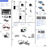
Box Inventory<br />
The <strong>DF64</strong> <strong>Digital</strong> <strong>Frame</strong> box contains the following items.<br />
Description Part # Qty<br />
<strong>DF64</strong> <strong>Digital</strong> Audio <strong>Frame</strong> 946-06938-01<br />
Power supply, <strong>DF64</strong> 600-06829-00 1<br />
Dummy power supply 946-06940 1<br />
Rackmount Hardware 936-06541-01 2<br />
Power Cord, IEC/US, 8’ 032-03613-00 1<br />
Front Panel Blank, Modular 726-06526-01 *<br />
Card, FC631 <strong>Frame</strong> Controller 946-07106-01 1<br />
FC631 Pack 936-07226-01 1<br />
Card, MM641 MADI Interface 946-07105-01 2<br />
MM641 Pack 936-07227-01 2<br />
Card, SP661 Signal Processor 946-07113-01 *<br />
<strong>DF64</strong> <strong>Manual</strong> 1<br />
* - Number varies depending on configuration ordered.<br />
Safety and Precautions<br />
1) Read Instructions - Read all the safety and operation instructions before operating the<br />
<strong>DF64</strong> <strong>Digital</strong> <strong>Frame</strong>.<br />
2) Heed Warnings – Follow all warnings on the <strong>DF64</strong> and in these operating instructions.<br />
3) Water and Moisture – Do not use the <strong>DF64</strong> near water.<br />
4) Heat – Locate the <strong>DF64</strong> away from heat sources.<br />
5) Power Sources – Connect the Am713/MA703 only to a power supply of the type<br />
described in these operation instructions or as marked on the <strong>DF64</strong>.<br />
6) Power Cord Protection – Route power cords so that they are not likely to be walked<br />
upon or pinched by items placed on them.<br />
7) Object and Liquid Entry – Do not drop objects or spill liquids on the <strong>DF64</strong>.<br />
8) Damage Requiring Service – The <strong>DF64</strong> should be serviced only by qualified personnel<br />
when:<br />
a) Objects have fallen, or liquid has spilled into the <strong>DF64</strong>; or<br />
b) The <strong>DF64</strong> does not appear to operate or exhibits a marked change in<br />
performance; or,<br />
c) The <strong>DF64</strong> have been dropped or there is damage to a chassis.<br />
9) Servicing – Do not attempt to service the <strong>DF64</strong> beyond those means described in this<br />
operation manual. All other servicing should be referred to the <strong>Euphonix</strong> Tech Support<br />
department.<br />
<strong>DF64</strong> <strong>Digital</strong> <strong>Frame</strong> <strong>Manual</strong> Version 1.0 ©1999 <strong>Euphonix</strong>, Inc. Page 4
10) Fuse replacement – To prevent electric shock and avoid risk of fire, replace fuse only<br />
with the same type and rating.<br />
11) To prevent electric shock, do not use the <strong>DF64</strong> polarized plug with and extension cord,<br />
receptacle or other outlet unless the blades can be fully inserted to prevent blade<br />
exposure.<br />
12) Grounding or Polarization – Do not defeat the grounding or polarization of the <strong>DF64</strong>.<br />
13) Cooling - Ventilation for cooling is provided to the <strong>DF64</strong> via four rear panel mounted<br />
fans. These fans draw cooling air through the chassis from the openings on the front<br />
panel. To avoid damage to the unit, do not block the fans or the front panel openings.<br />
Do not disconnect the fans.<br />
THERE ARE NO USER SERVICEABLE PARTS IN THE <strong>DF64</strong>. However, individual cards<br />
can be swapped by the user.<br />
Power On Sequence<br />
CE/TUV/UL/CSA<br />
It is recommended that the <strong>DF64</strong> <strong>Digital</strong> <strong>Frame</strong>(s) are powered on after all the other System<br />
5 components have been powered on and the Virtual Mixer has been loaded in all the<br />
corresponding <strong>Digital</strong> Pilot computers.<br />
The <strong>DF64</strong> is fully CE compliant. Documentation is available from the factory.<br />
<strong>DF64</strong> <strong>Digital</strong> <strong>Frame</strong> <strong>Manual</strong> Version 1.0 ©1999 <strong>Euphonix</strong>, Inc. Page 5
Component Overview<br />
Functional Description<br />
Applications<br />
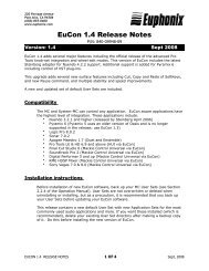
The <strong>DF64</strong> <strong>Digital</strong> <strong>Frame</strong> is the <strong>Digital</strong> Signal Processing Center of System 5. <strong>Digital</strong> Audio is<br />
routed to and from the <strong>DF64</strong> in MADI. Control of the <strong>DF64</strong> is provided by a <strong>Digital</strong> Pilot<br />
Computer (one per <strong>DF64</strong>,) which in turn communicates with the System 5 Control Surface. Thus<br />
the <strong>DF64</strong> is under control of the System 5 system operator.<br />
The <strong>DF64</strong> assembly is a standard 19” rack width and 9RU high.<br />
In its role of <strong>Digital</strong> Signal Processing Center for System 5 , the <strong>DF64</strong> performs three<br />
functions;<br />
• Signal I/O<br />
• Signal Routing and Synchronization<br />
• Signal Processing<br />
There are 3 different types of cards in the <strong>DF64</strong> that address each of the above functions.<br />
The number and type of cards in the <strong>DF64</strong> are configurable. There are one to four <strong>DF64</strong><br />
frames per System 5 , each of which can contain up to 14 cards. One SC253d <strong>Digital</strong> Pilot is<br />
required for each <strong>DF64</strong>.<br />
Signal I/O– MM641 MADI Interface Card<br />
All audio I/O is handled by the MM641 MADI Interface Card. MADI signals input at 24 bit<br />
fixed point resolution are converted to 32 bit floating point resolution for distribution over the<br />
backplane to other cards (the SP-661 Signal Processor Cards use 40 bit floating point<br />
processing internally—see below). Each MM641 card can input 224channels and output 224<br />
channels of audio (56 channels per MADI port.) The MADI cards can also support 64 channel<br />
MADI if an application requires this. When operating at 96kHz sample rates, each MADI port<br />
handles 28 audio channels.<br />
Signal Routing and Synchronization – FC631 <strong>Frame</strong> Controller Card<br />
All patching between I/O, Channels, and Busses is done on the Time Division<br />
Multiplexed(TDM_ bus and controlled by the FC631 <strong>Frame</strong> Controller Card. The FC631 Card<br />
also provides a FireWire interface to the SC253d Pilot Computer. The <strong>DF64</strong> includes a slot for a<br />
backup FC631 card, for applications where maximum fault tolerance is required.<br />
The <strong>DF64</strong> typically acts as a Sample Rate Slave in System 5 synchronization, although it can<br />
be a Master if desired. The Sync Source section on the FC631 front panel allows the user to<br />
select between AES or Word Sync (slave mode) or Internal Sync (master mode). Once locked to<br />
the selected sync source, the FC631 distributes a sync clock to the other cards in the <strong>DF64</strong><br />
frame and outputs a reference clock on its AES and Word sync output connectors. The master<br />
Sample Rate clock signal for the <strong>DF64</strong> and all System 5 system components comes from the<br />
Studio Hub (SH612), which in turn can be used to synchronize other digital components in the<br />
studio.<br />
<strong>DF64</strong> <strong>Digital</strong> <strong>Frame</strong> <strong>Manual</strong> Version 1.0 ©1999 <strong>Euphonix</strong>, Inc. Page 6
Signal Processing – SP661 Signal Processor Card<br />
The SP661 Signal Processor card performs all signal processing functions in the <strong>DF64</strong>. This<br />
card comprises six Analog Devices SHARC processors, massive DMA facilities for transferring<br />
audio data, and a RISC CPU for management of card functions. The programmable DSP<br />
architecture on the SP661 card allows it to perform channel processing, mixing, or various other<br />
signal processing tasks.<br />
<strong>DF64</strong> <strong>Digital</strong> <strong>Frame</strong> <strong>Manual</strong> Version 1.0 ©1999 <strong>Euphonix</strong>, Inc. Page 7
Hardware Operation<br />
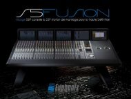
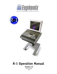
Dimensions and Weight<br />
Height: 15.75 inches<br />
Width: 19 inches<br />
Depth: 17.3 inches<br />
Weight: 72lbs (approx) with 9-SP661, 1-FC631, 2-MM641 cards, and 1-power supply. Weight<br />
can vary with configuration.<br />
19”<br />
17”<br />
16”<br />
Front<br />
17”<br />
Rear<br />
<strong>DF64</strong> <strong>Digital</strong> <strong>Frame</strong> <strong>Manual</strong> Version 1.0 ©1999 <strong>Euphonix</strong>, Inc. Page 8<br />
15.75”<br />
5<br />
17.3”<br />
17”<br />
Side
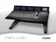
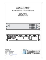
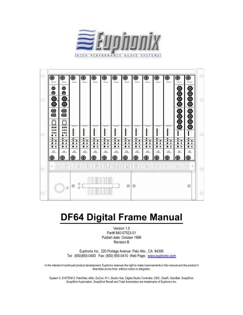
Front Panel, FC631 <strong>Frame</strong> Controller<br />
AES Sync In (3-pin Lemo Female) AES/EBU formatted sync input. The<br />
<strong>DF64</strong> clocks to the signal at this port when Sync Source is set to<br />
AES. An XLR female to LEMO adapter cable is provided.<br />
AES Sync Out (3-pin Lemo Male) AES/EBU formatted sync output. This<br />
signal is active regardless of the selected sync source. A LEMO<br />
to XLR male adapter cable is provided.<br />
Word In (BNC) TTL-level square wave Sync Input. <strong>DF64</strong> Sample<br />
rate is clocked to the signal at this port when Sync Source is set<br />
to Word.<br />
Word Out (BNC) TTL-level square wave sync output. This signal is<br />
active regardless of selected sync source.<br />
IEEE 1394 ports (2) (IEEE 1394) High speed communication interface to the<br />
SC253d Pilot Computer. This interface carries real-time control<br />
and metering data between the SC253d and the <strong>DF64</strong>. The<br />
cable from the SC253d can be plugged into either of the two<br />
ports.<br />
Chassis ID Display Each <strong>DF64</strong> chassis must be assigned a unique ID which<br />
identifies it among multiple frames in a system. The ID is set<br />
using a rotary switch located on the Backplane PCB. The<br />
System is shipped with the ID switch preset to the proper<br />
number, so users will not normally need to access the switch.<br />
The switch position must match that of the corresponding <strong>Digital</strong><br />
Pilot computer.<br />
Sync Source LEDs The top three LEDs in the Sync Source section indicate<br />
the selected sync source: AES, Word, or Internal. The sync<br />
source is changed by pressing the select button (a paper clip or<br />
similar tool is required) Refer to the System 5 Operation <strong>Manual</strong><br />
for information on changing the sync source.<br />
Sample Rate LEDs The bottom six LEDs in the Sync Source section indicate<br />
the sample rate that is measured by the FC-631 card. Standard<br />
sample rates include 44.1kHz, 48kHz, 96kHz, and the 0.1% “pullup”<br />
and “pull-down” rates associated with each of these standard<br />
rates. If the FC631 is locked to a non-standard sample rate, the<br />
CUSTOM LED will be lit.<br />
Select Button Use this button to manually select the Sync source (and<br />
Sample Rate, if Internal Sync is selected) Refer to the System 5<br />
Operation <strong>Manual</strong> for information on changing the sync source.<br />
Locked LED Indicates that the FC631card is receiving and locked to<br />
the selected sync source. This LED must be lit to ensure<br />
proper audio operation of the <strong>DF64</strong>. .<br />
Active LED When lit, Indicates that the FC631 is actively controlling<br />
the TDM bus. In a system with two FC631 cards, this LED is<br />
<strong>DF64</strong> <strong>Digital</strong> <strong>Frame</strong> <strong>Manual</strong> Version 1.0 ©1999 <strong>Euphonix</strong>, Inc. Page 9<br />
In<br />
Out<br />
In<br />
Out<br />
<strong>Euphonix</strong><br />
AES Sync<br />
Word Sync<br />
FireWire<br />
Chassis ID<br />
Sync Source<br />
AES Word Int<br />
44.1 48 96<br />
PU PD Custom<br />
Select<br />
Active<br />
5V<br />
Locked<br />
Reset Error<br />
HotSwap Ready<br />
FC-631<br />
FRAME<br />
CONTROLLER<br />
75<br />
3V
used to determine which card is Active and which is on stand-by.<br />
5V, 3V LEDs Indicate that 5 volt and 3 volt power are present.<br />
Reset Button This button forces a manual reset of the FC631 card.<br />
Error LED Indicates that an error condition has been detected on the<br />
FC631. It is normal for this LED to remain lit for 30 seconds or<br />
more after the <strong>DF64</strong> is powered on.<br />
HotSwap Button Push this button prior to making a swap of the FC631<br />
Card. In a system fitted with two FC-631 cards, the backup card<br />
will take over when the HotSwap button is pressed on the active<br />
card (supported in v2.0).<br />
Ready LED Indicates that FC631 is disconnected from the <strong>DF64</strong><br />
system bus and ready for removal.<br />
<strong>DF64</strong> <strong>Digital</strong> <strong>Frame</strong> <strong>Manual</strong> Version 1.0 ©1999 <strong>Euphonix</strong>, Inc. Page 10
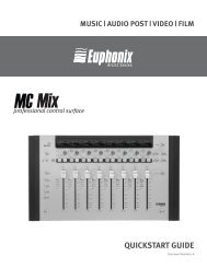
Front Panel, MM641 MADI Interface Card<br />
MADI In Ports(4) (BNC) <strong>Digital</strong> audio signal input. Each port can receive 56<br />
or 64 channels of audio at sample rates up to 48kHz, or 28 or 31<br />
channels at 96kHz.<br />
MADI Out Ports(4) (BNC) <strong>Digital</strong> audio signal output. Each port can transmit<br />
56 or 64 channels of audio at Sample Rates up to 48kHz, or 28<br />
or 31 channels at 96kHz.<br />
MADI Input OK LEDs Indicate that a MADI signal is present at the respective<br />
input port(s). A flashing LED indicates a protocol or sync error<br />
on the incoming MADI line.<br />
Mute Indicates that all channels of audio from the MM641 to the<br />
TDM bus are muted. MADI output channels are muted<br />
automatically if the hardware detects a corrupted signal.<br />
5V, 3V LEDs Indicate that 5 volt and 3 volt power are present.<br />
Reset Button This button forces a manual reset of the MM641 card.<br />
Error LED Indicates that an error condition has been detected on the<br />
MM641 card. It is normal for the Error LED to be lit for 30<br />
seconds or more after the <strong>DF64</strong> has been powered on.<br />
HotSwap Button Push this button prior to making a swap of the MM641<br />
card.<br />
Ready LED Indicates that the MM641 card is disconnected from the<br />
<strong>DF64</strong> system bus and ready for removal.<br />
MADI Input OK<br />
A<br />
B<br />
<strong>DF64</strong> <strong>Digital</strong> <strong>Frame</strong> <strong>Manual</strong> Version 1.0 ©1999 <strong>Euphonix</strong>, Inc. Page 11<br />
A<br />
B<br />
C<br />
D<br />
A<br />
B<br />
C<br />
D<br />
<strong>Euphonix</strong><br />
MADI Inputs<br />
MADI Outputs<br />
Mute<br />
5V<br />
C<br />
D<br />
Reset Error<br />
HotSwap Ready<br />
MM-641<br />
MADI<br />
INTERFACE<br />
3V
Front Panel, SP661 Signal Processing Card<br />
DSP Activity LEDs These LEDs indicate the level of processing activity on<br />
each of the SP661 Sharc processors. The lights glow more<br />
brightly as each Sharc increases its processing activity.<br />
Mute Indicates that all Audio signals from the SP661 to the TDM<br />
bus are muted.<br />
5V, 3V LEDs Indicate that 5 volt and 3 volt power are present.<br />
Reset Button This button forces a manual reset of the SP661 card.<br />
Error LED Indicates that an error condition has been detected on the<br />
SP661 card. Is is normal for the Error LED to remain lit for 30<br />
seconds or more after the <strong>DF64</strong> is powered on<br />
HotSwap Button Push this button prior to making a swap of the SP661 Card.<br />
Ready LED Indicates that the SP661 card is disconnected from the<br />
<strong>DF64</strong> system bus and ready for removal.<br />
<strong>Euphonix</strong><br />
DSP Activity<br />
<strong>DF64</strong> <strong>Digital</strong> <strong>Frame</strong> <strong>Manual</strong> Version 1.0 ©1999 <strong>Euphonix</strong>, Inc. Page 12<br />
5V<br />
A<br />
B<br />
C<br />
D<br />
E<br />
F<br />
Mute<br />
Reset Error<br />
HotSwap Ready<br />
SP-661<br />
SIGNAL<br />
PROCESSOR<br />
3V
Technical Specifications<br />
Performance Specifications<br />
Sync sources: Word Sync, AES<br />
Word Sync In 1 BNC<br />
AES Sync In 1 Lemo 3-pin (adapter to XLR female provided)<br />
Internal Fs: 44.1, 48, 96 kHz +/-20ppm<br />
Sample Rate Range (Fs)<br />
Locking to External Source: 40,000Hz → 48,480Hz (in single speed mode)<br />
80,000Hz 96,960Hz (in double speed mode)<br />
Sync Outputs: AES and Word Sync<br />
Word Clock Out 1 BNC<br />
AES Sync Out 1 Lemo 3-pin (adapter to XLR male available)<br />
MADI<br />
MADI input: 4 (BNC) 75ohms, 56 channel (with nominal Sample Rates ≥40kHz and<br />
≤48.48kHz) Full 24-bit precision.<br />
“MADI Input OK” LED per input port<br />
MADI output: 4 (BNC) 75ohms, 56 channel (with nominal Sample Rates ≥40kHz and<br />
≤48.48kHz) Full 24-bit precision.<br />
Backplane 684-channel pipelined TDM bus (32-bit floating point audio data)<br />
342 channels at 80kHz -> 96.96kHz operation<br />
32-bit floating-point audio data format (converted to/from 24-bit<br />
24-bit fixed point on MM641 Card)<br />
DSP 40-bit floating-point internal computation<br />
32-bit floating point maintained throughout all internal paths<br />
7.5 GFLOPS Peak DSP horsepower per <strong>DF64</strong> <strong>Frame</strong><br />
(using 9 SP661 Cards and 2 MM641 Cards)<br />
29.8 GFLOPS Peak DSP horsepower per system<br />
(4 <strong>DF64</strong> frames)<br />
Total Harmonic Distortion 0.005% or better, 20Hz ~ 20kHz, -18dBFS (through any audio path)<br />
Audio Throughput Delay 44 Samples Typical (MADI In -> Channel -> Mix Bus -> Monitor Bus -><br />
MADI Out )<br />
(0.92 msec @ Fs=48kHz, 0.46 msec @ Fs=96kHz<br />
Delay remains constant with EQ/Filters/Dynamics In or Out<br />
Additional user-adjustable delay per channel (up to 240 samples)<br />
FireWire (IEEE1394) 2 ports on FC631 front panel.<br />
Used for real-time system control and configuration<br />
200Mbps max data rate<br />
<strong>DF64</strong> <strong>Digital</strong> <strong>Frame</strong> <strong>Manual</strong> Version 1.0 ©1999 <strong>Euphonix</strong>, Inc. Page 13
Environmental Requirements<br />
Operating Temperature: 0 to 35 degrees Celsius (ambient)<br />
Storage Temperature: -10 to 55 degrees Celesius<br />
Humidity: 0 to 90% non-condensing<br />
Power Requirements<br />
Serviceability<br />
90 to 254 Volts AC (rms), 50/60Hz, 400 Watts Max<br />
Maximum inrush current at power-on: 40 Amps<br />
Specifications subject to change without notice.<br />
All active modules (Cards, Power supplies) can be inserted or removed with power on.<br />
Redundant Power supply available.<br />
Redundant DSP and <strong>Frame</strong> Controller Cards supported in v2.0<br />
<strong>DF64</strong> <strong>Digital</strong> <strong>Frame</strong> <strong>Manual</strong> Version 1.0 ©1999 <strong>Euphonix</strong>, Inc. Page 14