Installation Guide CM404 CM416, pdf - Avid
Installation Guide CM404 CM416, pdf - Avid
Installation Guide CM404 CM416, pdf - Avid

Create successful ePaper yourself
Turn your PDF publications into a flip-book with our unique Google optimized e-Paper software.
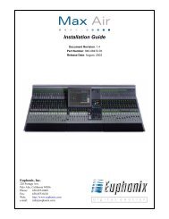
404 416<br />
Max Air Surfaces<br />
<strong>Installation</strong> Manual<br />
Document Revision: A<br />
Part Number: 840-11316-01<br />
Release Date: August 2010<br />
Euphonix is <strong>Avid</strong>. Learn more at www.avid.com
Regulatory and Safety Notices<br />
FCC Notice<br />
Part 15 of the Federal Communication Commission Rules and Regulations has established Radio<br />
Frequency (RF) emission limits to provide an interference free radio frequency spectrum. Many<br />
electronic devices produce RF energy incidental to their intended purpose.<br />
These rules place electronic equipment into two classes, A and B, depending on the intended use.<br />
Class A devices are those that may be expected to be installed in a business or commercial environment.<br />
Class B devices are those that may be expected to be installed in a home or residential environment. The<br />
FCC requires devices in both classes to be labeled with the interference likelihood and additional<br />
operating instructions. The rating label on the equipment will show which class the product is (A or B).<br />
Class A product will not have an FCC logo. Class B equipment will have an FCC logo. The information<br />
statements differ on the two classes.<br />
Class A Equipment<br />
This equipment has been tested and found to comply with the limits for a Class A digital device,<br />
pursuant to Part 15 of the FCC rules. These limits are designed to provide reasonable protection against<br />
harmful interference when the equipment is operated in a commercial environment. This equipment<br />
generates, uses, and can radiate radio frequency energy and, if not installed and used in accordance<br />
with the instructions, may cause harmful interference to radio communications. Operation of this<br />
equipment in a residential area is likely to cause harmful interference, in which case the user will be<br />
required to correct the interference at personal expense.<br />
Euphonix is <strong>Avid</strong>. Learn more at www.avid.com
Modifications<br />
The FCC requires the user to be notified that any changes or modifications made to <strong>Avid</strong> hardware that<br />
are not expressly approved by <strong>Avid</strong> Technology may void the user’s authority to operate the equipment.<br />
Cables<br />
Connections to <strong>Avid</strong> hardware must be made with shielded cables with metallic RFI/EMI connector<br />
hoods in order to maintain compliance with FCC Rules and Regulations.<br />
PRODUCTS WITH MULTIPLE POWER INPUTS:<br />
WARNING: Each power input is intended to be connected to a separate branch circuit. Risk of high<br />
leakage exists if multiple inputs are connected to a single source and protective earth is not present. A<br />
QUALIFIED SERVICE PERSON shall verify that each socket-outlet from which the equipment is to be<br />
powered provides a connection to the building protective earth. If any do not provide this connection,<br />
the QUALIFIED SERVICE PERSON shall arrange for the installation of a PROTECTIVE EARTHING<br />
CONDUCTOR from the separate protective earthing terminal to the protective earth wire in the building.<br />
Canadian ICES-003<br />
Class A Equipment<br />
This Class A digital apparatus meets all requirements of the Canadian Interference-Causing Equipment<br />
Regulations.<br />
Cet appareil numérique de la classe A respecté toutes les exigences du Règlement sur le matériel<br />
brouilleur du Canada.<br />
Euphonix is <strong>Avid</strong>. Learn more at www.avid.com
European Union Declaration of Conformity<br />
Declaration of conformity<br />
Konformitätserklärung<br />
Déclaration de conformité<br />
Declaración de Confomidad<br />
Verklaring de overeenstemming<br />
Dichiarazione di conformità<br />
We/Wir/ Nous/WIJ/Noi:<br />
<strong>Avid</strong> Technology<br />
1925 Andover Street<br />
Tewksbury, MA, 01876 USA<br />
European Contact: Nearest <strong>Avid</strong> Sales and Service Office or<br />
<strong>Avid</strong> Technology International B.V.<br />
Sandyford Industrial Estate<br />
Unit 38, Carmanhall Road<br />
Dublin 18, Ireland<br />
declare under our sole responsibility that the product,<br />
erklären, in alleniniger Verantwortung,daß dieses Produkt,<br />
déclarons sous notre seule responsabilité que le produit,<br />
Euphonix is <strong>Avid</strong>. Learn more at www.avid.com
declaramos, bajo nuestra sola responsabilidad, que el producto,<br />
verklaren onder onze verantwoordelijkheid, dat het product,<br />
dichiariamo sotto nostra unica responsabilità, che il prodotto,<br />
Product Name(s) : Max Air Surface Modules<br />
Model Number(s): 404, 416<br />
Product Options: This declaration covers all options for the above product(s).<br />
to which this declaration relates is in conformity with the following standard(s) or other normative<br />
documents.<br />
auf das sich diese Erklärung bezieht, mit der/den folgenden Norm(en) oder Richtlinie(n)<br />
übereinstimmt.<br />
auquel se réfère cette déclaration est conforme à la (aux) norme(s) ou au(x) document(s)<br />
normatif(s).<br />
al que se refiere esta declaración es conforme a la(s) norma(s) u otro(s) documento(s)<br />
normativo(s).<br />
waarnaar deze verklaring verwijst, aan de volende norm(en) of richtlijn(en) beantwoordt.<br />
a cui si riferisce questa dichiarazione è conforme alla/e seguente/i norma/o documento/i<br />
normativo/i.<br />
The requirements of the European Council:<br />
Safety: Directive 2006/95/EC<br />
EN 60065:2002 /A1:2006<br />
EMC: Directive 2004/108/EC<br />
EN 55103-1:1996<br />
EN 55103-2:1996<br />
Euphonix is <strong>Avid</strong>. Learn more at www.avid.com
LED Safety Notices<br />
<strong>Avid</strong> hardware might contain LED or Laser devices for communication use. These devices are compliant<br />
with the requirements for Class 1 LED and Laser Products and are safe in the intended use. In normal<br />
operation the output of these laser devices does not exceed the exposure limit of the eye and cannot<br />
cause harm.<br />
Standard to which conformity is declared: (IEC 60825-1)<br />
Optical connections are located on the rear panel and are typically labeled “Optical” or “SPDIF/ADAT.”<br />
The exact location of optical connections is identified more clearly elsewhere in the documentation for<br />
the <strong>Avid</strong> hardware device.<br />
Disposal of Waste Equipment by Users in the<br />
European Union<br />
Euphonix is <strong>Avid</strong>. Learn more at www.avid.com
Rack-mount Requirements<br />
The following rack-mount requirements are listed below:<br />
• Elevated Operating Ambient — If installed in a closed or multi-unit rack assembly, the operating ambient<br />
temperature of the rack environment might be greater than room ambient. Therefore, consider installing the<br />
equipment in an environment compatible with the maximum ambient temperature (Tma) specified by the<br />
manufacturer.<br />
• Reduced Air Flow — <strong>Installation</strong> of the equipment in a rack should be such that the amount of air flow<br />
required for safe operation of the equipment is not compromised. Do not block vents.<br />
• Mechanical Loading — Mounting of the equipment in the rack should be such that a hazardous condition is<br />
not achieved due to uneven mechanical loading.<br />
• Circuit Overloading — Consideration should be given to the connection of the equipment to the supply<br />
circuit and the effect that overloading of the circuits might have on overcurrent protection and supply wiring.<br />
Appropriate consideration of equipment nameplate ratings should be used when addressing this concern.<br />
• Reliable earthing — Reliable earthing of rack-mounted equipment should be maintained. Particular<br />
attention should be given to supply connections other than direct connections to the branch circuit (for<br />
example, use of power strips).<br />
Euphonix is <strong>Avid</strong>. Learn more at www.avid.com
Lithium Battery Replacement<br />
If a battery is supplied in this <strong>Avid</strong> product it must only be replaced by qualified personnel. Contact <strong>Avid</strong><br />
Customer Support for assistance.<br />
WARNING<br />
Danger of explosion if battery is incorrectly replaced. Replace with only the same or equivalent type<br />
recommended by the manufacturer. Dispose of used batteries according to the manufacturer’s<br />
instructions.<br />
ADVARSEL!<br />
Lithiumbatteri - Eksplosionsfare ved fejlagtig håndtering. Udskiftning må kun ske med batteri af<br />
samme fabrikat og type. Levér det brugte batteri tilbage til leverandøren.<br />
ADVARSEL!<br />
Lithiumbatteri - Eksplosjonsfare. Ved utskifting benyttes kun batteri som anbefalt av<br />
apparatfabrikanten. Brukt batteri returneres apparatleverandøren.<br />
VARNING<br />
Explosionsfara vid felaktigt batteribyte. Använd samma batterityp eller en ekvivalent typ som<br />
rekommenderas av apparattillverkaren. Kassera använt batteri enligt fabrikantens instruktion.<br />
VAROITUS<br />
Paristo voi räjähtää, jos se on virheellisesti asennettu. Vaihda paristo ainoastaan laitevalmistajan<br />
suosittelemaan tyyppiin. Hävitä käytetty paristo valmistajan ohjeiden mukaisesti.<br />
Euphonix is <strong>Avid</strong>. Learn more at www.avid.com
Euphonix Max Air Control Surface Manual<br />
Table of Contents<br />
System Startup Sequence ..........................................................................................7<br />
Description ................................................................................................................7<br />
Overview.........................................................................................................7<br />
Self Test Procedure ...................................................................................................9<br />
Initiating Self Test...........................................................................................9<br />
Switch and Knob Test.....................................................................................9<br />
LED Test.......................................................................................................10<br />
Fader Test......................................................................................................10<br />
Display Test ..................................................................................................11<br />
Memory Test.................................................................................................11<br />
Selecting and Adjusting the Onscreen Display .......................................................12<br />
Touchscreen Alignment ..........................................................................................13<br />
Changing the ID of a <strong>CM416</strong> Module ....................................................................15<br />
System Ethernet IP Addresses.................................................................................15<br />
Technical Specifications .........................................................................................16<br />
Power ............................................................................................................16<br />
Environmental Requirements........................................................................16<br />
Dimensions....................................................................................................17<br />
User Reference ........................................................................................................19<br />
Internal Components.....................................................................................19<br />
Fans ...............................................................................................................20<br />
v
Euphonix Max Air Control Surface Manual<br />
List of Figures<br />
1 Typical Console Layout ......................................................................................................7<br />
2 <strong>CM404</strong> Rear Panel ..............................................................................................................8<br />
3 <strong>CM416</strong> Rear Panel ..............................................................................................................8<br />
4 Control surface self-test keys ..............................................................................................9<br />
5 12<br />
6 13<br />
7 13<br />
8 14<br />
9 Changing the <strong>CM416</strong> ID ...................................................................................................15<br />
10 Side Dimensions ...............................................................................................................17<br />
11 <strong>CM416</strong> Bottom Dimensions .............................................................................................17<br />
12 <strong>CM404</strong> Bottom Dimensions .............................................................................................18<br />
13 Max Air Top Dimensions .................................................................................................18<br />
14 <strong>CM404</strong> ..............................................................................................................................19<br />
15 <strong>CM416</strong> ..............................................................................................................................19<br />
vi
Euphonix Max Air Control Surface Manual<br />
System Startup Sequence<br />
Description<br />
Overview<br />
See page 21 in the Max Air Operation Manual for the system startup sequence.<br />
The Max Air Console consists of a configurable number of Control Modules that comprise<br />
the Control Surface. The Max Air Control Surface is the digital control center for<br />
all Max Air system components and communicates with them via Ethernet network<br />
connections. Control signals are transmitted via the Ethernet switch and distributed to<br />
the Max Air system components. No audio passes through the Control Surface.<br />
The Max Air console must contain a <strong>CM404</strong> center section module and can have up to<br />
three fully loaded <strong>CM416</strong> 16-channel Modules, each with 16 physical faders. The system<br />
can have up to 48 faders, not including the eight faders in the <strong>CM404</strong> master section.<br />
The <strong>CM416</strong>HL and <strong>CM416</strong>HR are half-loaded (left or right) 8-fader modules that can<br />
be used to expand your system.<br />
<strong>CM416</strong><br />
Sixteen-channel Module<br />
<strong>CM404</strong><br />
Center Section<br />
Figure 1 Typical Console Layout<br />
7<br />
<strong>CM416</strong><br />
Sixteen-channel Module
Euphonix Max Air Control Surface Manual<br />
Rear Panels<br />
INTERNAL<br />
TALKBACK MIC EXTERNAL<br />
TALKBACK MIC<br />
TO KVM<br />
EXTENDER<br />
MOUSE<br />
KEYBOARD<br />
SERVICE SERIAL 1 SERIAL 2<br />
Figure 2 <strong>CM404</strong> Rear Panel<br />
T 5.0 AH<br />
250 V<br />
Caution:<br />
To prevent risk<br />
of fire, replace<br />
fuse with the<br />
same type and<br />
rating.<br />
~100-240V<br />
AC<br />
50-60 Hz<br />
250 Watts<br />
LAN<br />
Figure 3 <strong>CM416</strong> Rear Panel<br />
Power Connectors (IEC): Accepts two standard IEC power cords (provided). Two autoranging<br />
switching supplies accept voltages between 100–240 VAC, 50–60 Hz.<br />
LAN Port (RJ45): Connect to EuCon Network Hub via RJ45 through the console<br />
ethernet harness (provided).<br />
To KVM Extender (RJ45): Connection to KVM extender (<strong>CM404</strong> only)<br />
Talkback (XLR): Connection to the internal and external talkback microphones.<br />
Keyboard and Mouse (PS2): Connection to the keyboard and mouse or trackball.<br />
Serial 1, 2 (DB9): RS232 serial ports (for service only).<br />
I<br />
O<br />
Service (DB15HD, PS2): VGA video and keyboard connection (for service only).<br />
8<br />
<strong>CM404</strong><br />
SERVICE<br />
SERIAL 1<br />
SERIAL 2<br />
LAN<br />
AC IN 1 AC IN 2<br />
I<br />
O<br />
T 5.0 AH<br />
250 V<br />
Caution:<br />
To prevent risk<br />
of fire, replace<br />
fuse with the<br />
same type and<br />
rating.<br />
~100-240V<br />
AC<br />
50-60 Hz<br />
250 Watts<br />
AC IN 1 AC IN 2<br />
T 5.0 AH<br />
250 V<br />
Caution:<br />
To prevent risk<br />
of fire, replace<br />
fuse with the<br />
same type and<br />
rating.<br />
~100-240V<br />
AC<br />
50-60 Hz<br />
250 Watts<br />
<strong>CM416</strong><br />
I<br />
I<br />
O<br />
O
Euphonix Max Air Control Surface Manual<br />
Self Test Procedure<br />
The following pages describe the operation of standalone self-test software for the Max<br />
Air control modules. The self-test code is designed to be invoked in a module right after<br />
power-up and before the Single Board Computer (SBC) downloads code.<br />
Initiating Self Test<br />
Enter Self Test<br />
Enter Other Tests<br />
Enter self-test by pressing the self-test enter keys shown below. This must be done before<br />
the SBC code download. If code download from the SBC occurs during the selftest,<br />
the module automatically exits self-test and executes the downloaded code. Use<br />
the keys shown below to perform the different tests. After entering the test, use the detailed<br />
description of each test on the following pages to navigate through different<br />
modes within a test.<br />
Group<br />
Group<br />
Group<br />
Group<br />
Group<br />
Group<br />
Group<br />
Group<br />
1 2 3 4 5 6 7 8 1 2 3 4 5 6 7 8 1 2 3 4 5 6 7 8 1 2 3 4 5 6 7 8 1 2 3 4 5 6 7 8 1 2 3 4 5 6 7 8 1 2 3 4 5 6 7 8 1 2 3 4 5 6 7 8<br />
9 10 11 12 13 14 15 16 9 10 11 12 13 14 15 16 9 10 11 12 13 14 15 16 9 10 11 12 13 14 15 16 9 10 11 12 13 14 15 16 9 10 11 12 13 14 15 16 9 10 11 12 13 14 15 16 9 10 11 12 13 14 15 16<br />
17 18 19 20 21 22 23 24 17 18 19 20 21 22 23 24 17 18 19 20 21 22 23 24 17 18 19 20 21 22 23 24 17 18 19 20 21 22 23 24 17 18 19 20 21 22 23 24 17 18 19 20 21 22 23 24 17 18 19 20 21 22 23 24<br />
25 26 27 28 29 30 31 32 25 26 27 28 29 30 31 32 25 26 27 28 29 30 31 32 25 26 27 28 29 30 31 32 25 26 27 28 29 30 31 32 25 26 27 28 29 30 31 32 25 26 27 28 29 30 31 32 25 26 27 28 29 30 31 32<br />
33 34 35 36 37 38 39 40 33 34 35 36 37 38 39 40 33 34 35 36 37 38 39 40 33 34 35 36 37 38 39 40 33 34 35 36 37 38 39 40 33 34 35 36 37 38 39 40 33 34 35 36 37 38 39 40 33 34 35 36 37 38 39 40<br />
41 42 43 44 45 46 47 48 41 42 43 44 45 46 47 48 41 42 43 44 45 46 47 48 41 42 43 44 45 46 47 48 41 42 43 44 45 46 47 48 41 42 43 44 45 46 47 48 41 42 43 44 45 46 47 48 41 42 43 44 45 46 47 48<br />
Aux<br />
Aux<br />
Aux<br />
Aux<br />
Aux<br />
Aux<br />
Aux<br />
Aux<br />
1 2 3 4 5 6 7 8 1 2 3 4 5 6 7 8 1 2 3 4 5 6 7 8 1 2 3 4 5 6 7 8 1 2 3 4 5 6 7 8 1 2 3 4 5 6 7 8 1 2 3 4 5 6 7 8 1 2 3 4 5 6 7 8<br />
9 10 11 12 13 14 15 16 9 10 11 12 13 14 15 16 9 10 11 12 13 14 15 16 9 10 11 12 13 14 15 16 9 10 11 12 13 14 15 16 9 10 11 12 13 14 15 16 9 10 11 12 13 14 15 16 9 10 11 12 13 14 15 16<br />
17 18 19 20 21 22 23 24 17 18 19 20 21 22 23 24 17 18 19 20 21 22 23 24 17 18 19 20 21 22 23 24 17 18 19 20 21 22 23 24 17 18 19 20 21 22 23 24 17 18 19 20 21 22 23 24 17 18 19 20 21 22 23 24<br />
Mix<br />
Mix<br />
Mix<br />
Mix<br />
Mix<br />
Mix<br />
Mix<br />
Mix<br />
A B C D E F G H A B C D E F G H A B C D E F G H A B C D E F G H A B C D E F G H A B C D E F G H A B C D E F G H A B C D E F G H<br />
Knobset *<br />
* * * * * * *<br />
Select<br />
Ins Inp<br />
Ins Inp<br />
Ins Inp<br />
Ins Inp<br />
Ins Inp<br />
Ins Inp<br />
Ins Inp<br />
Ins Inp<br />
Dyn<br />
Dyn<br />
Dyn<br />
Dyn<br />
Dyn<br />
Dyn<br />
Dyn<br />
Dyn<br />
Expand EQ<br />
EQ<br />
EQ<br />
EQ<br />
EQ<br />
EQ<br />
EQ<br />
EQ<br />
In Out Filt<br />
Filt<br />
Filt<br />
Filt<br />
Filt<br />
Filt<br />
Filt<br />
Filt<br />
Aux Pan<br />
Aux Pan<br />
Aux Pan<br />
Aux Pan<br />
Aux Pan<br />
Aux Pan<br />
Aux Pan<br />
Aux Pan<br />
Mix Group Mix Group Mix Group Mix Group<br />
Mix Group Mix Group Mix Group Mix Group<br />
Mix- Bus Mix- Bus Mix- Bus Mix- Bus Mix- Bus Mix- Bus Mix- Bus Mix- Bus<br />
Select<br />
On<br />
Select<br />
On<br />
Select<br />
On<br />
Select<br />
L<br />
L<br />
L<br />
L<br />
L<br />
L<br />
L<br />
L<br />
0<br />
0<br />
0<br />
0<br />
0<br />
0<br />
0<br />
0<br />
6<br />
6<br />
6<br />
6<br />
6<br />
6<br />
6<br />
6<br />
3<br />
3<br />
3<br />
3<br />
3<br />
3<br />
3<br />
3<br />
6<br />
6<br />
6<br />
6<br />
6<br />
6<br />
6<br />
6<br />
On<br />
On<br />
On<br />
On<br />
On<br />
On<br />
On<br />
On<br />
Copy Paste Copy Paste Copy Paste Copy Paste Copy Paste Copy Paste Copy Paste Copy Paste<br />
Talk<br />
Talk<br />
Talk<br />
Talk<br />
Talk<br />
Talk<br />
Talk<br />
Talk<br />
Swap<br />
Swap<br />
Swap<br />
Swap<br />
Swap<br />
Swap<br />
Swap<br />
Swap<br />
Swap Channel Swap Channel Swap Channel Swap Channel<br />
Swap Channel Swap Channel Swap Channel Swap Channel<br />
Main Channel<br />
Main Channel<br />
Main Channel<br />
Main Channel<br />
Main Channel<br />
Main Channel<br />
Main Channel<br />
Main Channel<br />
LEDs Faders Displays Memory Version XXXX XXXX<br />
Chan<br />
Chan<br />
Chan<br />
Chan<br />
Chan<br />
Chan<br />
Chan<br />
Chan<br />
Select<br />
Select<br />
Select<br />
Select<br />
Select<br />
Select<br />
Select<br />
Select<br />
Solo<br />
Solo<br />
Solo<br />
Solo<br />
Solo<br />
Solo<br />
Solo<br />
Solo<br />
On<br />
On<br />
On<br />
On<br />
On<br />
On<br />
On<br />
On<br />
Select<br />
Select<br />
Select<br />
Select<br />
Select<br />
Select<br />
Select<br />
Select<br />
M S M S M S M S M S M S M S M S<br />
Select<br />
Select<br />
Select<br />
Select<br />
Select<br />
Select<br />
Select<br />
Select<br />
12<br />
12<br />
12<br />
12<br />
12<br />
12<br />
12<br />
12<br />
48V<br />
48V<br />
48V<br />
48V<br />
48V<br />
48V<br />
48V<br />
48V<br />
Lock<br />
Lock<br />
Lock<br />
Lock<br />
Lock<br />
Lock<br />
Lock<br />
Lock<br />
ST<br />
ST<br />
ST<br />
ST<br />
ST<br />
ST<br />
ST<br />
ST<br />
Mix-<br />
Mix-<br />
Mix-<br />
Mix-<br />
Mix-<br />
Mix-<br />
Mix-<br />
Mix-<br />
6<br />
6<br />
6<br />
6<br />
6<br />
6<br />
6<br />
6<br />
0<br />
0<br />
0<br />
0<br />
0<br />
0<br />
0<br />
0<br />
6<br />
6<br />
6<br />
6<br />
6<br />
6<br />
6<br />
6<br />
12<br />
12<br />
12<br />
12<br />
12<br />
12<br />
12<br />
12<br />
clip<br />
clip<br />
clip<br />
clip<br />
clip<br />
clip<br />
clip<br />
clip<br />
18<br />
18<br />
18<br />
18<br />
18<br />
18<br />
18<br />
18<br />
12 24<br />
12 24<br />
12 24<br />
12 24<br />
12 24<br />
12 24<br />
12 24<br />
12 24<br />
24<br />
24<br />
24<br />
24<br />
24<br />
24<br />
24<br />
24<br />
48 12<br />
48 12<br />
48 12<br />
48 12<br />
48<br />
12<br />
48 12<br />
48 12<br />
48 12<br />
30<br />
30<br />
30<br />
30<br />
30<br />
30<br />
30<br />
30<br />
72 24<br />
72 24<br />
72 24<br />
72 24<br />
72 24<br />
72 24<br />
72 24<br />
72 24<br />
36<br />
42<br />
48<br />
60<br />
72<br />
Select<br />
On<br />
Select<br />
On<br />
Select<br />
On<br />
Select<br />
36<br />
42<br />
48<br />
60<br />
72<br />
Switch and Knob Test<br />
Select<br />
On<br />
Select<br />
On<br />
Select<br />
On<br />
Select<br />
36<br />
42<br />
48<br />
60<br />
72<br />
Select<br />
On<br />
Select<br />
On<br />
Select<br />
On<br />
Select<br />
36<br />
42<br />
48<br />
60<br />
72<br />
Select<br />
On<br />
Select<br />
On<br />
Select<br />
On<br />
Select<br />
36<br />
42<br />
48<br />
60<br />
72<br />
Momentary Switch Press<br />
Figure 4 Control surface self-test keys<br />
Pressing any switch toggles the switch value display from 00 to 01 and shows the<br />
switch number in the display.<br />
Knob Value Display<br />
Select<br />
On<br />
Select<br />
On<br />
Select<br />
On<br />
Select<br />
36<br />
42<br />
48<br />
60<br />
72<br />
Select<br />
On<br />
Select<br />
On<br />
Select<br />
On<br />
Select<br />
36<br />
42<br />
48<br />
60<br />
72<br />
XXXX<br />
Select<br />
On<br />
XXXX<br />
Select<br />
On<br />
Select<br />
On<br />
Select<br />
36<br />
42<br />
48<br />
60<br />
72<br />
Switch #<br />
Switch Value<br />
Enter Self Test<br />
Knob #<br />
Knob Value<br />
Enter Other Tests<br />
Oscillator Monitors<br />
On<br />
XXXX<br />
Setup<br />
R W G<br />
Solo<br />
XXXX<br />
Control Room<br />
Dim Cut<br />
Setup<br />
Main<br />
Level<br />
Spkrs<br />
Alt 1<br />
Clear<br />
Spkrs<br />
Solo<br />
Alt 2<br />
Spkrs<br />
R W G<br />
Setup Setup<br />
Dyn<br />
Comp<br />
Exp / Gate<br />
Attack Release Depth<br />
Dyn<br />
Select<br />
Soft<br />
Knobs<br />
Dyn In In Threshold Ratio<br />
Gain<br />
EQ<br />
Soft Knobs<br />
Aux<br />
Aux<br />
All<br />
Masters Sends<br />
Group Bus<br />
Clear<br />
Masters<br />
*<br />
Shelf Low Q Lo Mid Q Hi Mid Q Shelf High Q<br />
Copy<br />
Mix<br />
Masters<br />
Link<br />
To<br />
Faders<br />
Function<br />
Low Freq Lo Mid Freq Hi Mid Freq High Freq<br />
Setup<br />
LEDs Faders Displays Memory Version<br />
XXXX XXXX<br />
Select<br />
Chan<br />
Chan<br />
Chan<br />
Chan<br />
Chan<br />
Chan<br />
Chan<br />
Chan<br />
Workstation Select<br />
Select<br />
Select<br />
Select<br />
Select<br />
Select<br />
Select<br />
Select<br />
Talkback / Slate<br />
Solo<br />
Solo<br />
Solo<br />
Solo<br />
Solo<br />
Solo<br />
Solo<br />
Solo<br />
Talk To<br />
Custom<br />
All<br />
Band Low Gain Band Lo Mid Gain Band Hi Mid Gain Band<br />
Setup<br />
High Gain<br />
On<br />
On<br />
On<br />
On<br />
On<br />
On<br />
On<br />
On<br />
In<br />
In<br />
In<br />
In<br />
Talk To Talk To<br />
Select<br />
Select<br />
Select<br />
Select<br />
Select<br />
Select<br />
Select<br />
Select<br />
Mon A Mon B<br />
Custom<br />
Insert<br />
M S L<br />
M S L<br />
M S L<br />
M S L<br />
M S L<br />
M S L<br />
M S L<br />
M S L<br />
In<br />
EQ<br />
EQ<br />
Soft<br />
Setup<br />
In<br />
Select Knobs<br />
AA<br />
Select<br />
Select<br />
Select<br />
Select<br />
Select<br />
Select<br />
Select<br />
Select<br />
Layouts Snapshots Knobsets Custom Pan<br />
Filters LPF HPF BPF NCH<br />
LPF HPF BPF NCH<br />
Filters<br />
Type Type<br />
Select<br />
BB<br />
12<br />
12<br />
12<br />
12<br />
12<br />
12<br />
12<br />
12<br />
48V<br />
48V<br />
48V<br />
48V<br />
48V<br />
48V<br />
48V<br />
48V<br />
CC<br />
7<br />
8 9<br />
Lock ST<br />
Lock ST<br />
Lock ST<br />
Lock ST<br />
Lock ST<br />
Lock ST<br />
Lock ST<br />
Lock ST<br />
Soft<br />
Mix- 6<br />
Mix- 6<br />
Mix- 6<br />
Mix- 6<br />
Mix- 6<br />
Mix- 6<br />
Mix- 6<br />
Mix- 6<br />
Knobs<br />
In Surround In In Filter 1 In Filter 2<br />
D<br />
0<br />
0<br />
0<br />
0<br />
0<br />
0<br />
0<br />
0<br />
4<br />
5<br />
6<br />
LTM<br />
Input<br />
Input A<br />
6<br />
6<br />
6<br />
6<br />
6<br />
6<br />
6<br />
6<br />
Input B<br />
EE<br />
Input<br />
12<br />
12<br />
12<br />
12<br />
12<br />
12<br />
12<br />
12<br />
RTM A On Hi Z HPF<br />
Select<br />
1<br />
2<br />
3<br />
clip<br />
clip<br />
clip<br />
clip<br />
clip<br />
clip<br />
clip<br />
clip<br />
FF<br />
18<br />
18<br />
18<br />
18<br />
18<br />
18<br />
18<br />
18<br />
0<br />
0<br />
0<br />
0<br />
0<br />
0<br />
0<br />
0<br />
In Front Pan<br />
6<br />
6<br />
6<br />
6<br />
6<br />
6<br />
6<br />
6<br />
B On 48 V<br />
Balance<br />
Soft<br />
12 3 24<br />
12 3 24<br />
12 3 24<br />
12 3 24<br />
12 3 24<br />
12 3 24<br />
12 3 24<br />
12 3 24<br />
Mic Gain<br />
Knobs<br />
24 6<br />
24 6<br />
24 6<br />
24 6<br />
24 6<br />
24 6<br />
24 6<br />
24 6<br />
G<br />
Clear 0 Enter<br />
Pan Soft<br />
Trim<br />
48 12<br />
48 12<br />
48<br />
12<br />
48 12<br />
48<br />
12<br />
48 12<br />
48<br />
12<br />
48<br />
12<br />
30<br />
30<br />
30<br />
30<br />
30<br />
30<br />
30<br />
30<br />
Select Knobs<br />
72 24<br />
72 24<br />
72 24<br />
72 24<br />
72 24<br />
72 24<br />
72 24<br />
72 24<br />
H<br />
36<br />
36<br />
36<br />
36<br />
36<br />
36<br />
36<br />
36<br />
Selected<br />
One Shot<br />
Setup<br />
Setup<br />
42<br />
42<br />
42<br />
42<br />
42<br />
42<br />
42<br />
42<br />
Channel<br />
48<br />
48<br />
48<br />
48<br />
48<br />
48<br />
48<br />
48<br />
60<br />
60<br />
60<br />
60<br />
60<br />
60<br />
60<br />
60<br />
72<br />
72<br />
72<br />
72<br />
72<br />
72<br />
72<br />
72<br />
Turning any knob displays the hex value (00–60) of the knob and shows the knob number<br />
in the display.<br />
9<br />
PUSH<br />
Talkback Mic<br />
Switch #<br />
Switch Value<br />
Knob #<br />
Knob Value
Euphonix Max Air Control Surface Manual<br />
LED Test<br />
Fader Test<br />
LED loop<br />
This switch cycles through all the LED colors.<br />
Color Toggle<br />
These switches light all the LEDs of each color: green, red, yellow, orange<br />
All LEDS<br />
This turns all LEDs on.<br />
NOTE: To avoid overheating, the module should not be left with All LEDS on for more<br />
than 5 minutes.<br />
All Fader Up<br />
All faders all the way up.<br />
All Fader Down<br />
All faders all the way down.<br />
Fader Echo Test<br />
All faders follow the one fader touched.<br />
Fader Loop Test with Speed Control<br />
All faders cycle up and down at the speed determined by the speed control knob. This<br />
fader cycle test times out after 5 minutes to protect the faders from burning out.<br />
Backstop PFL Switch Test<br />
The Backstop PFL display lights up when a fader is pulled back to enable its backstop<br />
PFL switch. This mode is always active.<br />
Fader I/O<br />
• Fader Write value display<br />
Any value written to a fader is displayed in its designated fader write intelligent<br />
display. This mode is always active in fader test mode.<br />
• Fader Read value display<br />
All faders are continuously read and the read value is displayed in its designated<br />
fader read intelligent display.<br />
10
Euphonix Max Air Control Surface Manual<br />
Display Test<br />
Clear All<br />
Char Up<br />
Char Down<br />
Char E<br />
Char W<br />
Enumerate<br />
Memory Test<br />
ROM Test<br />
This test reads the ROM and computes and displays the checksum. The user/tester can<br />
match the checksum to a known good checksum (see below) to make sure ROM test is<br />
successful.<br />
<strong>CM404</strong> Checksum - 6514<br />
<strong>CM416</strong> Checksum - D308<br />
RAM Test<br />
This tests the upper unused portion of the CPU board RAM. The Pass display shows<br />
up when the test is done.<br />
PC104 RAM Test<br />
This test writes and reads the whole PC104 RAM and checks for errors. The Pass display<br />
shows up when the test is done.<br />
11
Euphonix Max Air Control Surface Manual<br />
Selecting and Adjusting the Onscreen Display<br />
The Touchscreen image controls are found on the panel behind the Touchscreen. If<br />
the image needs adjustment, access press the Menu button and follow the onscreen<br />
instructions.<br />
Figure 5<br />
12
Euphonix Max Air Control Surface Manual<br />
Touchscreen Alignment<br />
The Max Air Touchscreen can be calibrated using the Elo Touchscreen utility. Note<br />
that different users may have slightly different ways of touching the screen. If an operator<br />
finds they often miss onscreen objects, re-calibrate the touchscreen:<br />
1. Select Control Panel from the Start menu.<br />
Figure 6<br />
2. Double-touch Elo Touchscreen.<br />
The Elo popup appears.<br />
Figure 7<br />
13
Euphonix Max Air Control Surface Manual<br />
Figure 8<br />
3. Touch Align and follow the onscreen instructions.<br />
When asked to touch the targets on the screen, best results are achieved by touching the<br />
targets naturally without thinking too much about it. This aligns the touchscreen to an<br />
individual’s hand-eye coordination.<br />
14
Euphonix Max Air Control Surface Manual<br />
Changing the ID of a <strong>CM416</strong> Module<br />
1. Power cycle the module and then simultaneously press and hold the two lower<br />
knobs on the first strip before the module connects to the System PC (you have<br />
about 15 seconds).<br />
Change ID<br />
Figure 9 Changing the <strong>CM416</strong> ID<br />
2. Set the ID using the first strip only in each <strong>CM416</strong>. Do not set the ID using strip<br />
nine.<br />
The <strong>CM416</strong> displays shows “Position – 0000 Use 1st fader to set module position.”<br />
3. Move the fader on strip one to select the ID.<br />
The ID appears as a hexadecimal number (0=ID 1, 1=ID 2, 2=ID 3, 3=ID 4,<br />
4=ID 5, 5=ID 6).<br />
4. Press strip one’s fader Select key to commit to the new ID.<br />
The module continues to boot only after committing to the change.<br />
System Ethernet IP Addresses<br />
Select<br />
On<br />
Select<br />
On<br />
Select<br />
On<br />
Select<br />
On<br />
On<br />
On<br />
On<br />
On<br />
On<br />
On<br />
On<br />
Copy Paste Copy Paste Copy Paste Copy Paste Copy Paste Copy Paste Copy Paste Copy Paste<br />
System Computer 192.168.0.1<br />
Interface Pilot ID 9 192.168.0.208<br />
Digital Pilot ID 1 192.168.0.200<br />
<strong>CM404</strong> ID 10 192.168.0.19<br />
<strong>CM416</strong> Strip 1 ID 1 192.168.0.10<br />
Strip 9 ID 2 192.168.0.11<br />
Strip 17 ID 3 192.168.0.12<br />
Strip 25 ID 4 192.168.0.13<br />
Strip 33 ID 5 192.168.0.14<br />
Strip 41 ID 6 192.168.0.15<br />
Select<br />
On<br />
Select<br />
On<br />
Select<br />
On<br />
Select<br />
15<br />
Select<br />
On<br />
Select<br />
On<br />
Select<br />
On<br />
Select<br />
Select<br />
On<br />
Select<br />
On<br />
Select<br />
On<br />
Select<br />
Select<br />
On<br />
Select<br />
On<br />
Select<br />
On<br />
Select<br />
Select<br />
On<br />
Select<br />
On<br />
Select<br />
On<br />
Select<br />
Select<br />
On<br />
Select<br />
On<br />
Select<br />
On<br />
Select<br />
Select<br />
On<br />
Select<br />
On<br />
Select<br />
On<br />
Select
Euphonix Max Air Control Surface Manual<br />
Technical Specifications<br />
Power<br />
Voltage 100–240 VAC (RMS), 50/60 Hz<br />
Power Consumption 2 x 50 W per module<br />
3 A Per Input(US 117 V)<br />
1.5 A Per Input(Europe 230 V)<br />
3 A Per Input (Japan 100 V)<br />
Inrush Current 25 A<br />
Fuse T6.3AH, 250V<br />
Heat Dissipation <strong>CM404</strong> 520 BTU/hr<br />
<strong>CM416</strong> 600 BTU/hr<br />
<strong>CM416</strong>H 520 BTU/hr<br />
Environmental Requirements<br />
Operating Temperature 0–35°C (Ambient)<br />
Storage Temperature -10 to 55°C<br />
Humidity 0–90% non-condensing<br />
16
Euphonix Max Air Control Surface Manual<br />
Dimensions<br />
29.58<br />
0<br />
.900<br />
23.400<br />
24.300<br />
28.50<br />
75.00°<br />
22.42<br />
20.83<br />
22.42<br />
20.83<br />
<strong>CM404</strong> BALANCE POINT<br />
<strong>CM416</strong> BALANCE POINT<br />
11.42<br />
Figure 10 Side Dimensions<br />
1/4-20 THREADED<br />
INSERT 8 PLACES<br />
Figure 11 <strong>CM416</strong> Bottom Dimensions<br />
9.83<br />
17<br />
15.625<br />
11.42<br />
16.13<br />
Dimensions in inches<br />
9.83<br />
8.742<br />
KEEP CLEAR FOR<br />
VENTILATION<br />
KEEP CLEAR FOR<br />
VENTILATION<br />
0<br />
.53<br />
0<br />
4.39<br />
5.85<br />
16.25<br />
8.39<br />
6.78<br />
3.06<br />
2.06<br />
1.20<br />
0<br />
0<br />
.902<br />
11.723<br />
12.827<br />
23.648<br />
24.300
Euphonix Max Air Control Surface Manual<br />
29.58<br />
0.00<br />
5.85<br />
22.42<br />
20.83<br />
1/4-20 THREADED<br />
INSERT 8 PLACES<br />
11.42<br />
9.83<br />
Figure 12 <strong>CM404</strong> Bottom Dimensions<br />
35.43<br />
0.00<br />
Figure 13 Max Air Top Dimensions<br />
18<br />
8.742<br />
KEEP CLEAR<br />
FOR PROPER<br />
VENTILATION<br />
1.0 1.0<br />
0.00<br />
16.15<br />
22.30<br />
0.00<br />
.53<br />
0<br />
0<br />
.90<br />
1.79<br />
19.46<br />
21.40<br />
22.30<br />
24.30
Euphonix Max Air Control Surface Manual<br />
User Reference<br />
Internal Components<br />
Power<br />
Distribution<br />
Single Board<br />
Computer<br />
Power<br />
Distribution<br />
Figure 14 <strong>CM404</strong><br />
Figure 15 <strong>CM416</strong><br />
19<br />
KVM Extender<br />
Dual Power<br />
Connections<br />
Dual Power<br />
Connections<br />
Single Board<br />
Computer<br />
Dual Power<br />
Supplies<br />
Dual Power<br />
Supplies
Euphonix Max Air Control Surface Manual<br />
Fans<br />
The <strong>CM416</strong> modules have low-noise internal fans and a thermal sensor between the<br />
displays on strips five and six. If a module gets too hot, the fans automatically turn on<br />
at a low or high speed depending on the temperature. The fans turn off automatically<br />
when the internal temperature returns to normal.<br />
20