Airfoil selection - ITLiMS
Airfoil selection - ITLiMS
Airfoil selection - ITLiMS

Create successful ePaper yourself
Turn your PDF publications into a flip-book with our unique Google optimized e-Paper software.
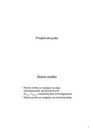
Wing<br />
<strong>Airfoil</strong> <strong>selection</strong><br />
• Aerodynamic characteristics (K max, C Lmax,<br />
stall characteristics)<br />
• Structural reasons;<br />
1
Leading<br />
edge<br />
Camber line<br />
<strong>Airfoil</strong> geometry<br />
<strong>Airfoil</strong> geometry<br />
Chord<br />
Maximum<br />
thickness<br />
position Maximum camber<br />
position<br />
Maximum<br />
camber<br />
Maximum<br />
thickness<br />
Trailing<br />
edge<br />
2
V ∞<br />
AoA=0°<br />
AoA=10°<br />
Angle of attack definition<br />
AoA<br />
AoA=15°<br />
Stall<br />
AoA=20°<br />
Separation point<br />
3
<strong>Airfoil</strong> aerodynamic characteristics<br />
Lift coefficient (C z or C L)<br />
CLMAX<br />
α 0<br />
/dα<br />
dC l<br />
Stall<br />
≡ a<br />
α KR<br />
Drag coefficient (C x or C D )<br />
<strong>Airfoil</strong> aerodynamic characteristics<br />
Design C z<br />
4
<strong>Airfoil</strong> aerodynamic characteristics<br />
Gliding ratio (C z / C x)<br />
Power factor<br />
(C z 3 / Cx 2 lub Cz 1,5 /Cx)<br />
<strong>Airfoil</strong> aerodynamic characteristics<br />
Pitching moment coefficient C m<br />
Derivative dCm/dCz<br />
is an indicator of<br />
stability.<br />
It is negative for<br />
stable aeroplanes<br />
and positive for<br />
unstable aeroplanes.<br />
5
Maximum thickness – t/c<br />
Chord - c<br />
Maximum<br />
thickness - t<br />
Effect of airfoil thickness on lift coefficient<br />
6%<br />
8%<br />
10%<br />
12%<br />
14%<br />
16%<br />
18%<br />
20%<br />
6
Effect of airfoil thickness on lift coefficient<br />
Effect of airfoil thickness on drag coefficient<br />
6%<br />
8%<br />
10%<br />
12%<br />
14%<br />
16%<br />
18%<br />
20%<br />
7
6%<br />
8%<br />
10%<br />
12%<br />
14%<br />
16%<br />
18%<br />
20%<br />
6%<br />
8%<br />
10%<br />
12%<br />
14%<br />
16%<br />
18%<br />
20%<br />
Effect of airfoil thickness on gliding ratio<br />
Effect of airfoil thickness on power factor<br />
8
Camber line<br />
0%<br />
0,5%<br />
1%<br />
1,5%<br />
2%<br />
2,5%<br />
3%<br />
3,5%<br />
Camber<br />
Maximum<br />
camber<br />
Effect of airfoil camber on lift coefficient<br />
9
Effect of airfoil camber on drag coefficient<br />
0%<br />
0,5%<br />
1%<br />
1,5%<br />
2%<br />
2,5%<br />
3%<br />
3,5%<br />
0%<br />
0,5%<br />
1%<br />
1,5%<br />
2%<br />
2,5%<br />
3%<br />
3,5%<br />
Effect of airfoil camber on gliding ratio<br />
10
0%<br />
0,5%<br />
1%<br />
1,5%<br />
2%<br />
2,5%<br />
3%<br />
3,5%<br />
Effect of airfoil camber on power factor<br />
Effect of airfoil camber on moment coefficient<br />
0%<br />
0,5%<br />
1%<br />
1,5%<br />
2%<br />
2,5%<br />
3%<br />
3,5%<br />
11
Position of<br />
maximum<br />
thickness<br />
Position of maximum thickness<br />
Boundary layer development<br />
laminar turbulent<br />
transition<br />
Maximum<br />
thickness<br />
separation<br />
separated<br />
12
Effect of airfoil „laminarity” on drag coefficient<br />
15%<br />
20%<br />
25%<br />
30%<br />
35%<br />
40%<br />
45%<br />
50%<br />
Effect of airfoil „laminarity” on lift coefficient<br />
15%<br />
20%<br />
25%<br />
30%<br />
35%<br />
40%<br />
45%<br />
50%<br />
13
15%<br />
15%<br />
Effect of camber line shape on moment coefficient<br />
28%<br />
22%<br />
28%<br />
22%<br />
35%<br />
0°<br />
2°<br />
4°<br />
6°<br />
Effect of camber line shape on gliding ratio<br />
35%<br />
0%<br />
2%<br />
4%<br />
6%<br />
14
Reynolds<br />
number effect on<br />
aerodynamic<br />
coefficients<br />
Effect of<br />
Mach<br />
number on<br />
lift<br />
coefficient<br />
15
Effect of<br />
Mach<br />
number<br />
on drag<br />
coefficient<br />
Effect of Mach number on moment<br />
coefficient<br />
16
Critical Mach<br />
number<br />
Historical values of an aeroplane airfoil thickness<br />
as a function of Mach number<br />
17
Critical Mach<br />
number<br />
Critical Mach<br />
number<br />
18
Calculate Reynolds number for design airspeed<br />
<strong>Airfoil</strong> <strong>selection</strong><br />
Re>3 000 000 3 000 000>Re>500 000 500 000>Re<br />
Calculate Mach number<br />
for maximum airspeed<br />
M max 0,75<br />
Wortmann catalogue<br />
„Stuttgarter<br />
Profilkatalog” Vol.1 i 2<br />
Selig catalogue<br />
„Summary of low speed<br />
airfoil data” Vol.1-3<br />
„<strong>Airfoil</strong>s at low speeds”<br />
Abbot catalogue „Theory of the wing section”, raport NACA 824, NASA TN D-7428<br />
Calculate Reynolds number for design<br />
airspeed<br />
Find characteristics for Re des i M des<br />
Calculate C L for design airspeed<br />
Supercritical airfoil eg. NASA SC(2) 714<br />
NASA TM X-1109<br />
NASA TM X-2977<br />
NASA TP 2969<br />
<strong>Airfoil</strong><br />
<strong>selection</strong><br />
Compare C D for C Ldes of available airfoils and select few best airfoils<br />
Compare C Lmax of selected airfoils<br />
Compare stall character of selected airfoils<br />
Compare C M of selected airfoils<br />
Select an airfoil with a combination of above features best suiting to the<br />
aeroplane mission<br />
19
Remaining wing features<br />
• Wing incidence;<br />
• Mean aerodynamic chord mac, c<br />
• Wing area (reference area) S;<br />
• Wing span b;<br />
• Wing aspect ratio A;<br />
• Wing dihedral;<br />
• Wing sweep angle (leading edge ΛLE, quarter chord Λc/4); • Taper ratio λ;<br />
• Geometrical and aerodynamic twist;<br />
• Winglets<br />
• Leading edges extensions;<br />
Wing incidence angle<br />
An angle between root chord and fuselage<br />
longitudinal axis<br />
20
c R<br />
c R<br />
c T<br />
S<br />
W<br />
S =<br />
W / S<br />
b = A ⋅ S<br />
c R<br />
T<br />
=<br />
b/2<br />
2⋅<br />
S<br />
[ b ⋅ ( 1 + λ)<br />
]<br />
c = λ ⋅ c<br />
R<br />
Taper ratio<br />
c T<br />
c<br />
λ =<br />
c<br />
T<br />
R<br />
Straight wings:<br />
λ=0.4÷0.5<br />
Swept wings:<br />
λ=0.2÷0.3<br />
Mean aerodynamic chord mac, c<br />
0,25mac<br />
Y<br />
c<br />
c R<br />
c T<br />
⎛ 2 ⎞<br />
c = ⎜⎝<br />
⎟⎠<br />
⋅ cROOT<br />
⋅<br />
3<br />
⎛ ⎞<br />
= ⎜ ⎟⋅<br />
⎝ 6 ⎠<br />
b<br />
Y<br />
2 ( 1+<br />
λλλλ + λλλλ )<br />
( 1+<br />
λλλλ )<br />
[ ( 1+<br />
2⋅<br />
λ )( 1+<br />
λ)<br />
];<br />
;<br />
21
Vortices generated by a wing<br />
Vortices generated by a wing and effect<br />
of aspect ratio on drag coefficient<br />
A<br />
=<br />
b<br />
S<br />
2<br />
C<br />
D<br />
=<br />
C<br />
D0<br />
2<br />
CL<br />
+<br />
π ⋅ A ⋅e<br />
22
Effect of aspect ratio (A, AR) on lift<br />
coefficient<br />
C<br />
b 1 b2<br />
b 3<br />
Wing dihedral angle<br />
φ – an angle between<br />
chords’ plane and<br />
horizontal plane<br />
b 4<br />
L<br />
α<br />
Unswept<br />
= C<br />
l<br />
α<br />
⋅<br />
⎛<br />
⎜⎜<br />
⎝<br />
C<br />
l<br />
π<br />
⎞<br />
⎟⎟ +<br />
⎠<br />
A<br />
⎛<br />
⎜⎜<br />
⎝<br />
A<br />
Wing dihedral<br />
Subsonic swept<br />
Supersonic swept<br />
ϕ<br />
α<br />
C<br />
Helmbolt equation<br />
=<br />
l<br />
π<br />
α<br />
2<br />
⎞<br />
⎟⎟<br />
⎠<br />
b 3
Λ c/4<br />
M eff =M ∞ cos(Λ LE )<br />
M kryt ~1/cos m (Λ LE )<br />
Wing sweep reduces<br />
effective Mach number.<br />
q eff=q ∞cos 2 (Λ LE)<br />
W~tan 2 (Λ LE)<br />
Wing sweep Λ LE , Λ c / 4,<br />
Λ t / c<br />
tan LE<br />
c / 4<br />
Λ LE<br />
Line connecting quarter<br />
chords along the wing span<br />
[ ( 1 − λ)<br />
/ A ⋅ ( + λ)<br />
]<br />
Λ = tan Λ +<br />
1<br />
Wing sweep<br />
Λ t/c<br />
Λ LE<br />
M<br />
McosΛ LE<br />
24
Wing sweep effect on dC L /dα<br />
dC<br />
dα<br />
L<br />
=<br />
2 +<br />
4 +<br />
β =<br />
eff<br />
( A ⋅β)<br />
2⋅<br />
π ⋅ A<br />
2<br />
2 ⎛ tan ( Λ ) ⎞ t / c<br />
⋅ ⎜⎜ 1 + ⎟ 2<br />
⎝ β ⎠<br />
2<br />
1− Meff<br />
M M cos Λ<br />
= ∞<br />
Wing sweep effect on separation<br />
LE<br />
25
Wing sweep at supersonic speeds<br />
Winglets<br />
26
Geometric twist<br />
Geometric twist<br />
Wing twist<br />
Aerodynamic twist<br />
Wing twist<br />
Aerodynamic twist<br />
27
AoA<br />
V<br />
Leading<br />
Edge<br />
eXtensions<br />
Delta wings<br />
28
LEX effect on lift coefficient<br />
Vortex generators<br />
RAF Museum Hendon<br />
29