zvezek 1 - ANG.indd - Rosenberg Belgium - Shop
zvezek 1 - ANG.indd - Rosenberg Belgium - Shop
zvezek 1 - ANG.indd - Rosenberg Belgium - Shop

Create successful ePaper yourself
Turn your PDF publications into a flip-book with our unique Google optimized e-Paper software.
KPF<br />
AKF<br />
AFV-8<br />
DPS<br />
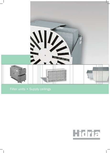
DUCT PRE-FILTER UNITS, HEPA FILTER UNITS, SUPPLY CEILINGS<br />
Duct pre-filter units KPF<br />
Duct units with Hepa filter<br />
Ceiling and wall units with Hepa filters<br />
LN-1<br />
AFV-8U<br />
Supply ceilings with Hepa filters<br />
Fluff separator LN and Filter grilles FR<br />
LN-2<br />
DSS<br />
AFV-8G<br />
FR<br />
AFH-1<br />
DUCT PRE-FILTER UNITS<br />
Duct pre-filter units KPF are designed to clean the<br />
air in air-conditioning and ventilating systems.<br />
Built-in filters are of F5 to F7 class. Various types of<br />
duct housings enable the air filtration with air flow<br />
from 3.400 m 3 /h up to 20.400 m 3 /h.<br />
HOUSINGS WITH HEPA FILTERS<br />
Duct HEPA filter units AKF are constructed for<br />
installation in duct system. Built-in filters of H10 to<br />
H13 class remove up to 85 % particles of 0,3 μm<br />
(filters H10) or up to 99,95 % particles of 0,3 μm<br />
(filters H13).<br />
Wall HEPA filter units (AFH) and ceiling HEPA filter<br />
units (AFV-8) are used in both, supply and exhaust<br />
air ventilation and air-conditioning installations,<br />
which require maximal cleanness of the air. Built-in<br />
Hepa filters are of H10 to H14 class. They filter and<br />
remove particles with a diameter of 0,3 μm in<br />
different levels: from 85 % (filters H10)<br />
up to 99,995 % (filters H14).<br />
Ceiling HEPA filter units type AFV-8 G has a<br />
special washer frame for attachment the filter via gel<br />
gasket. AFV-8 G version guarantee absolute sit<br />
tightness for the filters up to class U16, which<br />
remove 99,99995 % of particles with diameter of<br />
0,12 μm.<br />
SUPPLY CEILINGS<br />
Supply ceilings with built-in HEPA filters of H10 to<br />
H14 class, are used for clean rooms where air<br />
cleanness as well as intensive air-exchange is<br />
required. They are constructed to be built in false<br />
ceilings of operation rooms, intensive care premises<br />
and other clean rooms.<br />
FLUFF SEPARATOR AND FILTER GRILLES<br />
Fluff separators LN and Filter grilles FR are applied<br />
in air exhaust from clean rooms. They are designed<br />
for wall mounting.
ABSOLUTE AIR FILTRATION<br />
Pre-filter units Page<br />
Duct pre-filter units KPF........................................................................................................................................................................................................412<br />
Hepa filter units<br />
Duct Hepa filter units AKF ....................................................................................................................................................................................................414<br />
Wall Hepa filter units AFH-1 .................................................................................................................................................................................................418<br />
Ceiling Hepa filter units AFV-8 .............................................................................................................................................................................................420<br />
Ceiling Hepa filter units AFV-8U ..........................................................................................................................................................................................424<br />
Ceiling Hepa filter units with gel gasket AFV-8G .................................................................................................................................................................428<br />
Supply ceilings<br />
Perforated supply ceiling with Hepa filters DPS ....................................................................................................................................................................433<br />
Supply air ceiling - textile version DSS.................................................................................................................................................................................435<br />
Fluff separator<br />
Fluff separator LN-1...............................................................................................................................................................................................................438<br />
Fluff separator LN-2...............................................................................................................................................................................................................439<br />
Filter grilles<br />
Filter grille FR ......................................................................................................................................................................................................................440<br />
Filter class:<br />
Filter class EN 779 Efficiency (%)<br />
G 3 80-90<br />
G 4<br />
F 5<br />
F 6<br />
F 7 ≥ 90<br />
F 8<br />
F 9<br />
Filter class EN 1822-1 Efficiency (%) Size of the particles<br />
H 10 85<br />
H 11 95<br />
H 12 99,5<br />
H 13 99,95<br />
H 14 99,995<br />
U 15 99,9995<br />
U 16 99,99995<br />
U 17 99,999995<br />
> 0,3 μm<br />
> 0,12 μm
DUCT PRE-FILTER UNITS KPF<br />
1<br />
A<br />
3 2<br />
Component parts:<br />
1. Housing<br />
2. Cover plate<br />
3. Frame<br />
4. Bag filter<br />
412<br />
900<br />
4<br />
Detail A<br />
Table 1<br />
Pre-filter unit size, quantity and size of bag filters:<br />
1. Angle<br />
2. Gasket<br />
3. Gasket<br />
4. Filter<br />
5. Connecting part<br />
6. Filter frame<br />
H<br />
Duct pre-filter units KPF<br />
Application:<br />
Duct pre-filter units KPF are built in supply air<br />
installations before rooms, which demand higher<br />
air cleanness. KPF units extend the service life of<br />
Hepa filters, because larger dirty particles are<br />
removed by pre-filters, which are built in the<br />
system before Hepa filters.<br />
Description:<br />
KPF unit comprises filter of B x H x L<br />
dimensions, filter frames and bag filters of F5<br />
to F7 class. Filter housing is made of sheet metal,<br />
air-tight welded according to DIN 1946<br />
and coloured in RAL 9010. Housing is fitted<br />
with connections for measuring of pressure drop.<br />
Galvanized steel sheet KPF possible (not airtight).<br />
Installation:<br />
Basic frames are being fitted into the KPF<br />
units via the side opening. The procedure requires<br />
1000 mm of free space (fig. 2).<br />
KPF housing is fitted into the duct network<br />
via the self-locking flange.<br />
Size Flow Weight H B Bag filter FV-50/5<br />
(m 3 /h) (kg) (mm) (mm) 1 /1 595 x 595 1 /2 290 x 595 1 /4 290 x 290<br />
1A 3400 40 618 618 1 – –<br />
1B 5100 52 618 925 1 1 –<br />
1C 6800 63 618 1232 2 – –<br />
1D 8500 75 618 1539 2 1 –<br />
1E 10200 82 618 1846 3 – –<br />
2A 5100 53 925 618 1 – 2<br />
2B 7650 68 925 925 1 1 3<br />
2C 10200 82 925 1232 2 – 4<br />
2D 12750 91 925 1539 2 1 5<br />
2E 15300 110 925 1846 3 – 6<br />
3A 6800 63 1232 618 2 – –<br />
3B 10200 81 1232 925 2 2 –<br />
3C 13600 93 1232 1232 4 – –<br />
3D 17000 110 1232 1539 4 2 –<br />
3E 20400 123 1232 1846 6 – –<br />
B<br />
Fig. 2<br />
1000
Table 2<br />
Pre-filter dimensions 1<br />
/1 595 x 595 1<br />
/2 290 x 595 1<br />
/4 290 x 290<br />
Lenght (mm) 630 630 630<br />
Effective outlet area (m 2 ) 5,40 2,70 1,35<br />
No. of pockets 6 3 3<br />
Weight 2,90 1,45 0,72<br />
Average rate of synthetic dust filtering (%) 98 98 98<br />
Average rate of atmospheric dust filtering (%) 60 60 60<br />
Dust quantity (g) 960 480 240<br />
Flow (m 3 /h) 3400 1700 850<br />
Initial pressure drop (Pa) 68 68 68<br />
Final pressure drop (Pa) 350 350 350<br />
Outlet side designated according<br />
to DIN 24 185 2 nd part<br />
F5 to F7 F5 to F7 F5 to F7<br />
Inflammability according to DIN 53438 F1 F1 F1<br />
Temperature resistance (˚K) 343 343 343<br />
Manometer:<br />
Mark II 0-500 Pa Magnehelic 0-500 Pa<br />
It is recommended that a separate manometer is used for each filter unit. Upon customer's request we:<br />
- fix it on the filter housing<br />
- prepare a bracket for fixing<br />
- send a manometer without the bracket<br />
DUCT PRE-FILTER UNITS KPF TECHNICAL DATA<br />
Technical data:<br />
Bag filters from F5 to F7 are made of temperature<br />
hardened polyester fibres fitted<br />
on the self-supporting frames of stainless steel.<br />
See table 1 for characteristics of bag filters.<br />
Table comprises pre-filter combinations (fig. 2)<br />
and corresponded mounting dimensions B x H<br />
KPF units as well as air flow (Table 2).<br />
Possible filter elements combinations:<br />
Filter lifetime:<br />
Filter pollution is controlled by means of a<br />
differential manometer. The connections for plastic<br />
tubes are already fitted on the duct pre-filter units<br />
KPF.<br />
Ordering example:<br />
Designation: KPF - 2B<br />
Size: B x H = 1232 x 618<br />
Air flow volume: 7650 m 3 /h<br />
Pcs: 2<br />
On request it is possible to produce also KPF units<br />
for other dimensions, types and classes of filters.<br />
Galvanised steel sheet housing shall be defined<br />
upon the order.<br />
Manometers have to be ordered separately.<br />
Example of manometer order:<br />
Manometer Magnehelic 0-500 Pa, fitted on the<br />
housing.<br />
413
C<br />
DUCT HEPA FILTER UNITS AKF<br />
AKF-I<br />
AKF-II<br />
AKF-I<br />
A<br />
414<br />
H1<br />
775<br />
a1/b1<br />
1<br />
3<br />
695<br />
2 6 7<br />
5<br />
4<br />
Duct Hepa filter units AKF<br />
Application:<br />
Duct Hepa filter unit AKF is being used in the<br />
network of inlet and outlet ducts used to supply or<br />
extract air from the rooms with highest demands<br />
regarding air cleanness. Hepa filters of H10 to H14<br />
class prevent the intake or exhaust of particles<br />
larger than 0,3 μm . They can be installed as<br />
follows:<br />
• air supply and extract in laboratories<br />
• air supply and extract in operation rooms,<br />
infection- and sterile departments<br />
• air supply in electronics, precision mechanics,<br />
chemistry, pharmaceutics and food industry<br />
• air supply in film and audio tape industry<br />
• air supply and extract in nuclear technology etc.<br />
Description:<br />
AKF unit is made of filter housing, connection<br />
flanges (fig. 3) and Hepa filter. Filter is fitted with<br />
washer of a rectangular cross-section. Filter<br />
housing is made oh sheet metal air-tight welded<br />
according to DIN 1946 and coloured in RAL 9010.<br />
Two pressure gauge attachments for measuring of<br />
a pressure drop are incorporated into the housing.<br />
Bag-in, bag-out design<br />
(Safe filter replacement with the use of bags):<br />
“Bag-in, bag-out“ design is intended for filtration<br />
of air from the processes during which hazardous<br />
or toxic substances are produced. The bag-in-out<br />
system prevents any contact with the contents of a<br />
waste filter when replacing it. The installation of a<br />
pre-filter prolongs the life of a Hepa filter. The<br />
system of pre-filter replacement is the same as<br />
Hepa filter replacement.<br />
Installation and design variations:<br />
AKF housing are designed for installation of single<br />
AKF-I filter units. (fig. 1) as well as installation of<br />
several AKF-II units (fig. 2) into the duct system.<br />
To replace the filter, 700 mm of free space is<br />
required on the front side of the unit. AKF-II unit is<br />
made in several design variations, determined by<br />
the position of connection flanges A1, A2, B1, B2<br />
(fig. 4).<br />
Components:<br />
1. Housing<br />
2. Hepa filter (with semicircular gasket)<br />
3. Filter assembly levers<br />
4. Cover<br />
5. Cover fixing bolt<br />
6. DOP test connection<br />
7. Δp connection
C<br />
A<br />
H1 158 132<br />
B<br />
AKF-I combination with pre-filter<br />
Fig. 1<br />
AKF-II<br />
Fig. 2<br />
10<br />
b1<br />
775<br />
L<br />
450<br />
520<br />
Connection flanges<br />
775<br />
a1/b1<br />
82,5<br />
H1 158 132<br />
A<br />
C b1<br />
a1<br />
a1+60<br />
750<br />
82,5<br />
2<br />
1<br />
3<br />
1<br />
2<br />
3<br />
4<br />
DOP<br />
DOP<br />
a1<br />
623<br />
693<br />
p t +<br />
p -<br />
t<br />
p +<br />
t<br />
p t -<br />
b1<br />
30<br />
8<br />
b1+60<br />
9<br />
695<br />
9<br />
65 700<br />
Fig. 3: Connection flange dimensions Fig. 4: Position of flange connections<br />
DUCT HEPA FILTER UNITS AKF TECHNICAL DATA<br />
5<br />
6<br />
7<br />
Components:<br />
1. Housing<br />
2. Pre-filter<br />
3. Hepa filter<br />
4. Filter assembly levers<br />
5. Pre-filter cover<br />
6. Hepa filter cover<br />
7. Screws for cover fixing<br />
8. DOP test connection<br />
9. Δp connection<br />
Components:<br />
1. AKF-I (AKF-I with pre-filter)<br />
2. Connection duct<br />
3. Bases<br />
A1 A2<br />
B1 B2<br />
415
DUCT HEPA FILTER UNITS AKF TECHNICAL DATA<br />
Table 1<br />
p (Pa)<br />
400<br />
300<br />
250<br />
200<br />
100<br />
416<br />
Hepa filter unit type<br />
Designation AKF-I AKF-II/1, 2, 3, 4 AKF-II/2D, 4D, 6D, 8D<br />
No. of filters 1 1 2 3 4 2D 4D 6D 8D<br />
Flow (m 3 /h) 610x610x150 1200 1200 2400 3600 4800 2400 4800 7200 9600<br />
610x610x292 2400 2400 4800 7200 9600 4800 9600 14400 19200<br />
Lenght L / 733 1524 2315 3106 733 1524 2315 3106<br />
Flange a1 530 615 1260<br />
b1 545 200 300 400 500 200 300 400 500<br />
Hepa filter size A 328 328 328<br />
610x610x150 B / 833 1033 1233 1433 833 1033 1233 1433<br />
C 373 373 373<br />
H1 198 198 198<br />
Hepa filter A 470 470 470<br />
610x610x292 B / 975 1175 1375 1575 975 1175 1375 1575<br />
C 515 515 515<br />
H1 340 340 340<br />
Pre-filter A 618 618 618<br />
610x610x60 B / 1123 1323 1523 1723 1123 1323 1523 1723<br />
Hepa filter C 663 663 663<br />
610x610x150 H1 198 198 198<br />
Pre-filter A 760 760 760<br />
610x610x60 B / 1265 1465 1665 1865 1265 1465 1665 1865<br />
Hepa filter C 805 805 805<br />
610x610x292 H1 340 340 340<br />
Housing<br />
size<br />
Hepa Initial<br />
filter pressure (Pa)<br />
Flow<br />
(m<br />
Air velocity Max. temp. Humidity<br />
3 Table 2 Technical data for Hepa filters<br />
H1 610 x 610 x 150 250<br />
/h)<br />
1200<br />
(m/s)<br />
1.1<br />
(˚C)<br />
70<br />
(%)<br />
100<br />
Size and flow characteristics of Hepa filters<br />
installed in AKF unit are specified in table 2.<br />
H2 610 x 610 x 292 250 2400 2.4 70 100 Technical data for pre-filter<br />
Pressure drop diagram<br />
1 (610 x 610 x 150)<br />
(610 x 610 x 292)<br />
500 1000 1500 2000 2500 3000 3500<br />
Q (m 3 /h)<br />
2<br />
Unit size Pre-filter Initial pressure (Pa)<br />
H3 610 x 610 x 50 160<br />
Hepa filters of H10 to EU14 class conform<br />
to DIN 24 184, which means that the 0.3 μm<br />
particles are being removed within the of 85%<br />
to 99,995%, The initial pressure drop at nominal<br />
air flows from table 2 is 250 Pa. In case filters<br />
operate under the air flow volume larger or<br />
smaller than nominal air flow, pressure drop<br />
is being increased or decreased, respectively<br />
as shown in diagram.
Manometer:<br />
Mark II<br />
Fig. 4<br />
Ordering key<br />
AKF-II/1/H1/A1/bag in-out<br />
Combination AKF with pre-filter KPF<br />
A1<br />
A2<br />
B1<br />
B2<br />
H1 Filter size 610 x 610 x 150<br />
H2 Filter size 610 x 610 x 292<br />
1<br />
2<br />
3<br />
4<br />
2D<br />
4D<br />
6D<br />
8D<br />
AKF-I<br />
AKF-II<br />
Magnehelic<br />
Hepa filter (0-750 Pa)<br />
Pre-filter (0-500 Pa)<br />
It is recommended that a separate manometer is used for each filter unit. Upon customer's request we:<br />
- fix it on the filter housing<br />
- prepare a bracket for fixing<br />
- send a manometer without the bracket<br />
safe filter replacement<br />
Connection flange position<br />
Nominal size (Number of filters)<br />
Duct Hepa filter unit size<br />
AKF-II/1/H1/A1/bag in-out + KPF/H3/bag in-out<br />
(safe filter replacement)<br />
H3 pre-filter<br />
F7 610x610x50<br />
DUCT HEPA FILTER UNITS AKF TECHNICAL DATA<br />
Expected service life of Hepa filter<br />
and replacement<br />
Hepa filter are constructed for single use only.<br />
Expected service life of filter depends on air flow<br />
volume, pressure drop and amount of dust<br />
particles. When air flow volume is reduced<br />
for 25%, expected service life of Hepa filter<br />
doubles. Service life can be considerably<br />
increased with installation of pre-filter.<br />
Hepa filter pollution is controlled by means of a<br />
differential manometer (Picture 4) which is fitted<br />
on the housing.<br />
Connections for plastic tubes are fitted<br />
on AKF housing.<br />
The initial pressure drop is specified in table 2.<br />
When the pressure drop has reached double its<br />
initial value, it is recommended to replace the<br />
Hepa filter. When replacing the AKF filter, remove<br />
cover, release the lever and finally remove the<br />
frame with used Hepa filter. When installing the<br />
new filter, use the above instructions in opposite<br />
order.<br />
In case of replacement of filters using bags (bagin,<br />
bag-out system), the procedure is the same<br />
with the exception of a bag attached to the<br />
extension. The waste filter is removed into a bag,<br />
which has been attached to the extension since the<br />
last replacement. The bag is then hermetically<br />
closed so that after the separation of the part of the<br />
bag with the filter, a part of the bag remains on the<br />
extension, hermetically closed as well. A new filter<br />
is put in a bag and then placed over the remaining<br />
part closing the duct. Upon the placement of the<br />
new bag, the remaining part of the old bag is first<br />
removed into the new bag. A new filter is installed<br />
from the new bag. The bags are attached to the<br />
extension by means of a rubber collar.<br />
Ordering example:<br />
Designation: AKF-II/2/H2/A1<br />
No. of filters: 2<br />
Filter: H2 = 610 x 610 x 292<br />
H13 class (99,95 %)<br />
Air flow volume: 4800 m 3 /h<br />
Connection type: A1<br />
Pcs: 1<br />
On request it is possible to produce also AKF unit<br />
for other sizes of Hepa filters.<br />
Manometers have to be ordered separately.<br />
Example of manometer order:<br />
Manometer Magnehelic 0-750 Pa, fitted on the<br />
housing.<br />
417
726 x 421<br />
WALL HEPA FILTER UNITS AFH-1 TECHNICAL DATA<br />
Table 1<br />
Hepa filter unit Sit-tightness test Class<br />
AFH - 1/1 Sit-tightness and PAO test H12, H13, H14<br />
AFH - 1/3 PAO test H10, H11<br />
418<br />
A<br />
**<br />
*<br />
H<br />
Ho<br />
* Sit-tightness test<br />
** Pressure drop test<br />
381<br />
Connection flange<br />
351<br />
100<br />
100<br />
B<br />
1<br />
2<br />
3<br />
686<br />
656<br />
AFH 1/1<br />
AFH 1/3<br />
100 100<br />
9<br />
626<br />
1.<br />
2.<br />
3.<br />
732x427<br />
744x439<br />
321<br />
Detail A<br />
Detail A<br />
Detail B<br />
752x452<br />
Wall Hepa filter units AFH-1<br />
Application:<br />
Wall Hepa filter unit AFH-1 is being used in the network of inlet and outlet<br />
ducts used to supply or extract air from the rooms with highest demands<br />
regarding air cleanness. Hepa filters of H10 to H14 class<br />
prevent the intake or exhaust of particles larger than 0,3 μm. Hepa filter is fitted<br />
with a washer of a rectangular cross section. With the AFH1/3 version, the<br />
seal may also be semi-circular. They can be installed as follows:<br />
• air supply and extract in laboratories<br />
• air supply and extract in operating rooms, infection- and sterile<br />
departments<br />
• air supply in electronics, precision mechanics, chemistry, pharmaceutics<br />
and food industry<br />
• air supply in film and audio tape industry<br />
• air supply and extract in nuclear technology etc.<br />
Description:<br />
AFH-1 unit is made of filter housing, two-row steel grille JR-5 and Hepa filter.<br />
Filter housing made of sheet steel is air tight welded according to DIN 1946<br />
and coloured in RAL 9010. Grille is made of cold-drawn strip steel and<br />
coloured in RAL 9010. Grille is fastened to the housing via the nuts which can<br />
be tightened or unscrewed manually. AFH-1 unit is fitted with special sealing<br />
frame for sit-tightness test.<br />
Component parts:<br />
1. Housing<br />
2. Hepa filter (with flat gasket)<br />
3. Grille<br />
Design variations:<br />
The type of sealing frame determines three filter unit types and two Hepa<br />
filter sizes (AFH-1/1 and AFH-1/3, size 1 and 2).<br />
Installation:<br />
AFH-1 unit is designed for installation in the walls of the clean rooms.
Table 2<br />
Nominal size Hepa filter Ho H1 Grille JR-5<br />
1 305 x 610 x 150 338 150 725 x 425<br />
2 305 x 610 x 292 480 292 725 x 425<br />
Table 3<br />
Filter Hepa Initial Flow Air velocity Max. temp. Humidity<br />
unit size filter pressure (Pa) (m 3 /h) (m/s) (˚C) (%)<br />
1 305 x 610 x 150 250 850 0.90 70 100<br />
2 305 x 610 x 292 250 1700 2.20 70 100<br />
Pressure drop diagram<br />
300<br />
250<br />
200<br />
150<br />
100<br />
p (Pa)<br />
50<br />
1 (305 x 610 x 150)<br />
2 (305 x 610 x 292)<br />
200 600 1000 1600<br />
Mark II 0-700 Pa Magnehelic 0-750 Pa<br />
Fig. 4<br />
Fig. 5<br />
Q (m 3 /h)<br />
It is recommended that a separate manometer is used for each filter unit. Upon customer's request we:<br />
- fix it on the filter housing<br />
- prepare a bracket for fixing<br />
- send a manometer without the bracket<br />
Ordering key<br />
AFH-1/1 Size 1<br />
Hepa filter 1<br />
units size 2<br />
Tightness test 1<br />
3<br />
for filter 305 x 610 x 150<br />
for filter 305 x 610 x 292<br />
Tightness test and DOP test<br />
PAO test<br />
Hepa filter: size and filter class is to be specified independently.<br />
WALL HEPA FILTER UNITS AFH-1 TECHNICAL DATA<br />
Technical data:<br />
Size of grille regarding the size of housing and<br />
Hepa filter is specified in table 2. Technical data<br />
for the JR-5 grille are stated in the catalogue.<br />
Size and flow characteristics of Hepa filters<br />
installed in AFH-1 are specified in table 3.<br />
Hepa filters of H10 to H14 class conforms<br />
to DIN 24 184, which means that the 0.3 μm<br />
particles are being removed within the of 85%<br />
to 99,995%. The initial pressure drop at nominal<br />
air flows from table 3 is 250 Pa. In case filters<br />
operate under the air flow volume larger or<br />
smaller then nominal air flow, pressure drop<br />
is being increased or decreased, respectively<br />
as shown in diagram.<br />
Expected service life of Hepa filter<br />
and replacement:<br />
Hepa filters are constructed for single use only.<br />
Expected service life of filter depends on air flow<br />
volume, pressure drop and amount of dust<br />
particles. When air flow volume is reduced for<br />
25%, expected service life of Hepa filter<br />
doubles. Service life can be considerably<br />
increased with installation of pre-filter.<br />
Absolute filter pollution is controlled by means of<br />
a differential manometer (Picture 4) which is fitted<br />
on the housing.<br />
Connections for plastic tubes are fitted<br />
on AFH-1 housings.<br />
When the pressure drop has reached double its<br />
initial value, it is recommended to replace the<br />
Hepa filter. When replacing the AFH-1 filter,<br />
remove grille and screws on the holding bar<br />
and then remove the bar together with used filter.<br />
When installing the new filter use the above<br />
instructions in opposite order. The sit tightness<br />
is to be tested according to DIN 1946, chapter 4.<br />
The permeability at the test pressure of 2000 Pa<br />
should not exceed the values stated in standard.<br />
The checking is carried out with sit-tightness<br />
measuring device (fig. 5).<br />
Ordering example:<br />
Designation: AFH-1/1 JR-5<br />
Size: 1-with filter 305 x 610 x 150<br />
H13 class (99,95 %)<br />
Air flow volume: 600 m 3 /h<br />
Grille: JR-5<br />
Pcs: 12<br />
On request it is possible to produce also AFH-1<br />
units for other sizes of Hepa filters.<br />
Manometers have to be ordered separately.<br />
Example of manometer order:<br />
Manometer Magnehelic 0-750 Pa, fitted on the<br />
housing.<br />
419
CEILING HEPA FILTER UNITS AFV-8<br />
* Sit tightness test<br />
** Pressure drop test<br />
*<br />
420<br />
A<br />
Detail A<br />
1 2 3<br />
77.5 A 40<br />
3<br />
1<br />
2<br />
Ceiling Hepa filter units AFV-8<br />
Application:<br />
Ceiling Hepa filter units AFV-8 are used in supply or extract air applications in<br />
air conditioning and ventilating installations of the rooms with highest<br />
demands regarding air cleanness. Hepa filters of H10 to H14 class prevent the<br />
intake or exhaust of particles larger then 0,3 μm. They can be installed<br />
as follows:<br />
• air supply and extract in laboratories<br />
• air supply and extract in operating rooms, infection- and sterile<br />
departments<br />
• air supply in electronics, precision mechanics, chemistry, pharmaceutics<br />
and food industry<br />
• air supply in film and audio tape industry<br />
• air supply and extract in nuclear technology etc.<br />
Description:<br />
Ceiling Hepa filter unit AFV-8 is made of filter housing, standard diffusers<br />
KD-1, AKD-1, KD-6, OD-8 or OD-9 and Hepa filter. Filter is fitted with<br />
washer of a rectangular cross-section. Housing of sheet steel is air tight<br />
welded according to DIN 1946 and coloured in RAL 7001. Two pressure<br />
gauge attachments for measuring of a pressure drop are incorporated into the<br />
housing. Diffusers made of sheet steel are coloured in white (RAL 9010).<br />
AFV-8 housing has a special sealing frame designed to perform sit tightness<br />
test.<br />
Component parts:<br />
1. Housing<br />
2. Hepa filter (with flat gasket)<br />
3. Diffuser<br />
Installation:<br />
AFV-8 unit is constructed to fit into suspended ceilings.<br />
Types:<br />
The following Hepa filter units AFV-8 are possible:<br />
• with circular side entry spigot (AFV-8 RS) (fig. 1, table 1)<br />
• with circular top entry spigot (AFV-8 RV) (fig. 2, table 1)<br />
• with rectangular side entry spigot (AFV-8 KS) (fig. 3, table 3).<br />
AFV-8 with shut-off damper ZL-2<br />
Application:<br />
On the ceiling Hepa filter unit AFV-8 a shut-off damper ZL-2 is installed in the<br />
housing connection. The shut-off damper ZL-2 conforms to the DIN 1946/4<br />
standard requirements.<br />
The advantage of such a combination of an Hepa filter housing and a shut-off<br />
damper is the ability to close the shut-off damper during the filter exchange and<br />
thereby to prevent room air pollution. Upon the completion of the filter<br />
exchange, the shut-off damper is reopened. Such a filter exchange procedure<br />
eliminates the need to disinfect the room, which is mandatory in the case of<br />
exchanging the filter without shutting-off the inlet of non-filtered air.<br />
Description:<br />
On the connection of the standard ceiling Hepa filter unit AFV-8, a galvanised<br />
sheet steel shut-off damper is mounted by means of four screws. The damper<br />
may be controlled either manually or by means of an electric motor.<br />
Components:<br />
1. AFV-8/RS, RV<br />
2. ZL-2<br />
3. electric motor (with spring)
AFV-8 RS with circular side entry spigot<br />
Fig. 1<br />
D<br />
φ<br />
60<br />
A<br />
B1 x B1<br />
AFV-8 RV circular top entry spigot<br />
Fig. 2<br />
**<br />
A<br />
B1 x B1<br />
φ D<br />
J<br />
Bo<br />
A<br />
J<br />
Bo<br />
A<br />
50<br />
H<br />
**<br />
H<br />
60<br />
80<br />
H1<br />
H1 H3<br />
AFV-8 KS rectangular side entry spigot<br />
Fig. 3<br />
H2<br />
60<br />
A<br />
B1 x B1<br />
J<br />
Bo<br />
A<br />
50<br />
50<br />
H<br />
Ho<br />
Ho<br />
H1<br />
b2<br />
15<br />
b1<br />
82.5<br />
a2<br />
a1<br />
15<br />
11<br />
9<br />
CEILING HEPA FILTER UNITS AFV-8 TECHNICAL DATA<br />
Table 1<br />
Size Hepa filter φ D A Bo B1 J H0 H1 H3<br />
1 305 x 305 x 150 148 355 348 319 324 450 270 178<br />
2A 457 x 457 x 78 198 507 500 471 476 428 198 230<br />
2B 457 x 457 x 150 198 507 500 471 476 500 270 230<br />
3 610 x 610 x 78 198 660 653 624 629 428 198 230<br />
4 610 x 610 x 150 298 660 653 624 629 600 270 330<br />
5 610 x 610 x 292 348 660 653 624 629 792 412 378<br />
Table 2<br />
Size Hepa filter φ D A Bo B1 J Ho H1<br />
1 305 x 305 x 150 148 355 348 319 324 350 270<br />
2A 457 x 457 x 78 198 507 500 471 476 278 198<br />
2B 457 x 457 x 150 198 507 500 471 629 350 270<br />
3 610 x 610 x 78 198 660 653 624 629 278 198<br />
4 610 x 610 x 150 298 660 653 624 629 350 270<br />
5 610 x 610 x 292 348 660 653 624 629 492 412<br />
Table 3<br />
Size HEPA filter A Bo B1 J H1 H2 a1 b1 a2 b2<br />
1 305 x 305 x 150 355 348 319 324 270 400 250 100 285 136<br />
2A 457 x 457 x 78 507 500 471 476 198 328 400 100 435 131<br />
2B 457 x 457 x 150 507 500 471 476 270 400 400 100 435 136<br />
3 610 x 610 x 78 660 653 624 629 198 328 500 100 535 136<br />
4 610 x 610 x 150 660 653 624 629 270 460 560 160 595 196<br />
5 610 x 610 x 292 660 653 624 629 412 642 560 200 595 236<br />
421
CEILING HEPA FILTER UNITS AFV-8 TECHNICAL DATA<br />
Table 4<br />
p(Pa)<br />
400<br />
300<br />
250<br />
200<br />
100<br />
Filter Hepa D i f f u s e r s i z e **<br />
unit size filter A* KD-1 KD-6 OD-8K OD-9K<br />
1 305 x 305 x 150 355 x 355 1,2,3 400 – 400<br />
2A 457 x 457 x 78 507 x 507 3,4 500,600,625 500/16 500<br />
2B 457 x 457 x 150 507 x 507 3,4 500,600,625 500/16 500<br />
3 610 x 610 x 78 660 x 660 5,6,7,8 600,625 600/24, 625/54 600<br />
4 610 x 610 x 150 660 x 660 7,8 600,625 600/24, 625/54 600<br />
5 610 x 610 x 292 660 x 660 7,8 600,625 600/24, 625/54 600<br />
* Outer dimension of diffuser front plate.<br />
** Tehnical data for diffusers: see catalogue chapter 1.3.1. (for KD-1) (data for KD-15 are also valid for KD-6 ) and 1.3.2. (for KD-6, OD-8, OD-9).<br />
Table 5<br />
KD-1 KD-6<br />
OD-8K<br />
OD-9K<br />
Filter Hepa Initial Flow Air velocity Max. temp. Humidity<br />
unit size filter pressure (Pa) (m 3 /h) (m/s) (˚C) (%)<br />
1 305 x 305 x 150 250 290 1,0 70 100<br />
2A 457 x 457 x 78 250 660 1,1 70 100<br />
2B 457 x 457 x 150 250 660 1,1 70 100<br />
3 610 x 610 x 78 250 1200 1,1 70 100<br />
4 610 x 610 x 150 250 1200 1,1 70 100<br />
5 610 x 610 x 292 250 2400 2,4 70 100<br />
Pressure drop diagram<br />
1<br />
500<br />
1000<br />
2<br />
1500<br />
Dimensions of AFV-8 with shut-off damper ZL-2<br />
AFV-8 ZL-2<br />
size Hepa filter φD size A<br />
1 305x305x150 148 150 115<br />
2A 457x457x78 198 200 190<br />
2B 457x547x150 198 200 190<br />
3 610x610x78 198 200 190<br />
4 610x610x150 298 300 190<br />
5 610x610x292 348 350 220<br />
422<br />
3, 4<br />
2000<br />
2500<br />
3000<br />
Q (m 3 /h)<br />
5<br />
3500<br />
Diffuser types:<br />
• sheet steel painted in RAL<br />
• stainless sheet steel (except KD-1)<br />
• standard deflector colours are black<br />
Technical data:<br />
Possible combinations of diffuser size regarding<br />
the size of housing and Hepa filter is specified in<br />
table 4. Mounting dimensions of diffusers to be<br />
installed in AFV-8 are specified in tables 1, 2 and<br />
3 and in column A.<br />
Technical data of Hepa filters:<br />
Size and flow characteristics of Hepa filters<br />
installed in AFV-8 are specified in table 5.<br />
Hepa filters of H10 to H14 class conforms<br />
to DIN 24 184, which means that the 0.3 μm<br />
particles are being removed within the of 85%<br />
to 99,995%, The initial pressure drop at nominal<br />
air flows (table 5) is 250 Pa. In case filters operate<br />
under the air flow volume larger or smaller then<br />
nominal air flow, pressure drop is being increased<br />
or decreased, respectively as shown in diagram 1.<br />
Filter size<br />
1 305 x 305 x 150<br />
2A 457 x 457 x 78<br />
2B 457 x 457 x 150<br />
3 610 x 610 x 78<br />
4 610 x 610 x 150<br />
5 610 x 610 x 292
Mark II 0-700 Pa<br />
Fig. 4<br />
Fig. 5<br />
It is recommended that a separate manometer is used for each filter unit. Upon customer's request we:<br />
- fix it on the filter housing<br />
- prepare a bracket for fixing<br />
- send a manometer without the bracket<br />
Table 6<br />
Filter Hepa Flow Allowed.<br />
unit size filter (m 3 /h) permeability (%)<br />
1 305 x 305 x 150 290 2,9<br />
2A 457 x 457 x 78 660 6,6<br />
2B 457 x 457 x 150 660 6,6<br />
3 610 x 610 x 78 1200 12,0<br />
4 610 x 610 x 150 1200 12,0<br />
5 610 x 610 x 292 2400 30,0<br />
Ordering key<br />
AFV-8/RS1/ZL-2/R/KD-1 RAL 9010 Size 1<br />
RAL 9010<br />
INOX<br />
Diffuser KD-1<br />
AKD-1<br />
KD-6<br />
OD-8<br />
OD-9<br />
Damper control<br />
Shut-off<br />
damper<br />
Hepa 1<br />
filter 2A<br />
unit 2B<br />
size 3<br />
4<br />
5<br />
Connection RS<br />
RV<br />
KS<br />
size 1 ... 8 (only RAL 9010)<br />
R manual<br />
B electric motor<br />
ZL-2<br />
for filter 305 x 305 x 150<br />
for filter 457 x 457 x 78<br />
for filter 457 x 457 x 150<br />
for filter 610 x 610 x 78<br />
for filter 610 x 610 x 150<br />
for filter 610 x 610 x 292<br />
Circular side entry spigot *<br />
Circular top entry spigot *<br />
Rectangular side entry spigot *<br />
* The AFV-8 version with the shut-off damper ZL-2 is only availible with the<br />
RS and RV versions.<br />
Hepa filter: Size and filter class is to be specified independently.<br />
CEILING HEPA FILTER UNITS AFV-8 TECHNICAL DATA<br />
Expected service life of Hepa filter<br />
and replacement:<br />
Hepa filter are constructed for single use only.<br />
Expected service life of filter depends on air flow<br />
volume, pressure drop and amount of dust<br />
particles. When air flow volume is reduced for<br />
25%, expected service life of Hepa filter doubles.<br />
Service life can be considerably increased with<br />
installation of pre-filter. The dirtiness of the filter<br />
is controlled by the means of differential<br />
manometer fitted with U-tube (fig. 4).<br />
Connections for plastic tubes are fitted<br />
on AKF housing.<br />
The initial pressure drop is specified in table 5.<br />
When the pressure drop has reached double its<br />
initial value, it is recommended to replace the<br />
Hepa filter. When replacing the AFV-8 filter,<br />
remove diffuser and screws on the holding bar<br />
and then remove the bar together with used filter.<br />
When installing the new filter use the above<br />
instructions in opposite order. The sit tightness<br />
is to be tested according to DIN 1946 standard,<br />
chapter 4. The permeability at the test pressure<br />
of 2000 Pa should not exceed the values stated<br />
in standard (Table 6).<br />
The checking is carried out with sit-tightness<br />
measuring device (fig. 5).<br />
Ordering example:<br />
Designation: AFV-8/RS3/OD-9 RAL 9010<br />
Connection type: circular side entry<br />
spigot RS<br />
Size: 3-with filter 610 x 610 x 78<br />
H13 class (99,95 %)<br />
Air flow volume: 1200 m 3 /h<br />
Diffuser: OD-9 RAL 9010<br />
Pcs: 12<br />
On request it is possible to produce also AFV-8<br />
units for other sizes of HEPA filters.<br />
Manometers have to be ordered separately.<br />
Example of manometer order:<br />
Manometer Magnehelic 0-750 Pa, fitted on the<br />
housing.<br />
423
CEILING HEPA FILTER UNITS AFV-8U<br />
424<br />
A<br />
6 5<br />
A<br />
1<br />
2<br />
3<br />
4<br />
Ceiling Hepa filter units AFV-8U<br />
Application:<br />
Ceiling Hepa filter units AFV-8U are used in air supply or extraction applications<br />
in air conditioning and ventilation installations in rooms requiring the<br />
highest standards of air purity. Hepa filters of H10 to H14 class prevent the<br />
intake of particles larger than 0.3 μm.<br />
They can be installed as follows:<br />
• air supply and extract in laboratories<br />
• air supply and extract in infection- and sterile departments<br />
• air supply in electronics, precision mechanics, chemistry, pharmaceutics and<br />
food industry<br />
• air supply in film and audio tape industry<br />
Description:<br />
Ceiling Hepa filter units AFV-8U consists of the filter housing, standard diffuser<br />
and Hepa filter. The filter is fitted with a U-shaped washer, which enables<br />
testing of the sit tightness between filter and housing through the duct. Another<br />
solution is the semicircular gasket, which does not allow for airtighness testing<br />
between the filter and the housing. The lower part of the housing is made of<br />
sheet steel and is hermetically welded according to DIN 1946. The upper part is<br />
spot welded and attached to the lower part with the rivets. The housing is painted<br />
with RAL 9010. The diffuser (OD-9, KD-1, KD-6) is made of sheet steel and<br />
painted with RAL 9010 or is made of stainless steel. A perforated control<br />
damper can be built into the junction, and can be controlled easily from the<br />
clean side of the diffuser.<br />
Component parts:<br />
1. Plenum box<br />
2. Hepa filter housing<br />
3. Filter (version K - duct in the gasket or version P - semicircular gasket)<br />
4. Mask<br />
5. DOP test connection<br />
6. +Δp connection
Installation:<br />
Housing is adapted for suspended ceiling installation<br />
Installation T (traverse)<br />
Installation O (hangers)<br />
CEILING HEPA FILTER UNITS AFV-8U INSTALLATION<br />
Filter:<br />
Version K - filter with the duct in the gasket (enabling of airtightness testing) Version P - filter with the semicircular gasket (airtightness testing not possible)<br />
60-70<br />
35-70<br />
425
CEILING HEPA FILTER UNITS AFV-8U DIMENSIONS<br />
Dimensions:<br />
AFV-8U/RS with circular side entry spigot<br />
H0<br />
H1 H3<br />
H0<br />
H1 100<br />
426<br />
B2<br />
B1<br />
B0<br />
AFV-8U/RV with circular top entry spigot<br />
Diffusers types:<br />
A<br />
φ D<br />
B1<br />
B0<br />
A<br />
60<br />
KD-1 KD-6<br />
OD-9K<br />
60<br />
φ D<br />
Size Hepa filter φD A B0 B1 B2 H0 H1 H3<br />
1 305x305x80 158 415 409,5 380 265 343 133 210<br />
2 457x457x80 198 567 561,5 532 417 383 133 250<br />
3A 610x610x80 248 720 714,5 685 570 433 133 300<br />
3B 610x610x150 313 720 714,5 685 570 568 203 365<br />
3C 305x610x80 198 415x720 409,5x714,5 380x685 265x570 383 133 250<br />
4 610x915x80 313 720x1025 714,5x1019,5 685x990 570x875 498 133 365<br />
5 610x1220x80 348 720x1330 714,5x1324,5 685x1295 570x1180 533 133 400<br />
Size Hepa filter φD A B0 B1 B2 H0 H1<br />
1 305x305x80 158 415 409,5 380 265 233 133<br />
2 457x457x80 198 567 561,5 532 417 233 133<br />
3A 610x610x80 248 720 714,5 685 570 233 133<br />
3B 610x610x150 313 720 714,5 685 570 303 203<br />
3C 305x610x80 198 415x720 409,5x714,5 380x685 265x570 233 133<br />
4 610x915x80 313 720x1025 714,5x1019,5 685x990 570x875 233 133<br />
5 610x1220x80 348 720x1330 714,5x1324,5 685x1295 570x1180 233 133<br />
• steel sheet powder painted in RAL 9010<br />
• stainless steel (except KD-1)<br />
• standard colour of deflectors is black
Technical data of diffusers:<br />
Size Hepa External diffuser<br />
filter dimension<br />
A KD-1 KD-6 A ef (m 2 ) OD-9 A ef (m 2 )<br />
1 305 x 305 x 80 415 x 415 1,2,3 √ 0,0342 √ 0,0189<br />
2 457 x 457 x 80 567 x 567 2,3,4 √ 0,0743 √ 0,0414<br />
3A 610 x 610 x 80 720 x 720 5,6,7,8 √ 0,1368 √ 0,0651<br />
3B 610 x 610 x 150 720 x 720 5,6,7,8 √ 0,1368 √ 0,0651<br />
3C 305 x 610 x 80 415 x 720 - √ 0,0684 √ 0,0288<br />
4 610 x 915 x 80 720 x 1025 - √ 0,198 √ 0,1088<br />
5 610 x 1220 x 80 720 x 1330 - √ 0,2664 √ 0,1348<br />
The table indicates possible combinations of diffuser sizes according to housing and Hepa filter size.<br />
Technical data of Hepa filters:<br />
AFV-8U/RS1/K/T/OD-9 RAL 9010<br />
CEILING HEPA FILTER UNITS AFV-8U TECHNICAL DATA<br />
KD-1 A ef (m 2 )<br />
1 0.0104<br />
2 0.0185<br />
3 0.0279<br />
4 0.0440<br />
5 0.0628<br />
6 0.0728<br />
7 0.1175<br />
8 0.1280<br />
H13 H14<br />
Size Hepa Initial pressure Flow Initial pressure Flow Max. temp Humidity<br />
filter (Pa) (m 3 /h) (Pa) (m 3 /h) (˚C) (%)<br />
1 305 x 305 x 80 250 300 125 150 80 100<br />
2 457 x 457 x 80 250 740 125 340 80 100<br />
3A 610 x 610 x 80 250 1400 125 600 80 100<br />
3B 610 x 610 x 150 250 1530 - - 80 100<br />
3C 305 x 610 x 80 250 640 125 300 80 100<br />
4 610 x 915 x 80 250 2150 125 900 80 100<br />
5 610 x 1220 x 80 250 2900 125 1200 80 100<br />
Ordering key<br />
RAL 9010<br />
INOX<br />
Diffuser KD-1<br />
KD-6<br />
OD-9<br />
stainless steel<br />
Installation T (traverse)<br />
O (hangers)<br />
Filter<br />
size 1 ... 8 (RAL 9010 only)<br />
K (duct in the gasket)<br />
P (semicircular gasket)<br />
Hepa filter 1 for filter 305 x 305 x 80<br />
unit size 2 for filter 457 x 457 x 80<br />
3A for filter 610 x 610 x 80<br />
3B for filter 610 x 610 x 150<br />
3C for filter 305 x 610 x 80<br />
4 for filter 610 x 915 x 80<br />
5 for filter 610 x 1220 x 80<br />
Connection RS Circular side entry spigot<br />
RV<br />
Circular top entry spigot<br />
427
CEILING HEPA FILTER UNITS WITH GEL GASKET AFV-8G<br />
1<br />
2<br />
3<br />
C<br />
428<br />
A<br />
* PAO (before: DOP) connection on the housing top section<br />
** Pressure drop test<br />
Detail “A” Detail “C” Spring<br />
claw<br />
fastener<br />
gel gasket<br />
1 2 3<br />
77.5<br />
*<br />
A 40<br />
**<br />
D<br />
Ceiling Hepa filter units with gel gasket AFV-8G<br />
Application :<br />
Ceiling Hepa filter unit with gel gasket AFV-8G are installed in ventilating and<br />
air conditioning systems in rooms which require absolutely clean air. They can<br />
be used for both, air supply and extract applications. Hepa filters stop the<br />
particles as larger as 0,3 μm if they conform H14 class or even 0,12 μm if<br />
they conform U15 and U16 classes.<br />
Applications:<br />
• air supply and extract in laboratories<br />
• air supply and extract in operating theatres, infection- and sterile departments<br />
• air supply in electronics, precision mechanics, chemistry, pharmaceutics<br />
and food industry<br />
• air supply in film and audio tape industry<br />
• air supply and extract in nuclear technology etc.<br />
Description:<br />
Ceiling Hepa filter unit with gel gasket AFV-8G is made filter housing, standard<br />
diffusers KD-1, AKD-1, KD-6, OD-8 or OD-9 and Hepa filter. Housing of<br />
sheet steel is air tight welded according to DIN 1946 and coloured in RAL<br />
7001. Diffusers are made of sheet steel and coloured in white (RAL 9010).<br />
AFV-8G housing has a special sealing frame designed to fit “gasket” filters.<br />
Component parts:<br />
1. Housing<br />
2. Hepa filter (with gel gasket)<br />
3. Diffuser<br />
Advantage of gel gasket:<br />
With liquid sealant force, necessary to hold the filter is smaller, compared with<br />
neoprene washers, permitting lighter and cheaper housing and faster filter<br />
replacement.<br />
Installation:<br />
AFV-8G unit is constructed to fit into suspended ceilings.<br />
Types:<br />
The following ceiling Hepa filter units with gel gasket are possible:<br />
• with circular side entry spigot (AFV-8G RS) (fig. 1, table 1)<br />
• with circular top entry spigot (AFV-8G RV) (fig. 2, table 1)<br />
• with rectangular side entry spigot (AFV-8G KS) (fig. 3, table 3).<br />
AFV-8G with shut-off damper ZL-2<br />
Application:<br />
On the Ceiling Hepa filter units with gel gasket AFV-8G a shut-off damper ZL-2<br />
is installed in the housing connection. The shut-off damper ZL-2 conforms to<br />
the DIN 1946/4 standard requirements.<br />
The advantage of such a combination of an Hepa filter housing and a shut-off<br />
damper is the ability to close the shut-off damper during the filter exchange and<br />
thereby to prevent room air pollution. Upon the completion of the filter<br />
exchange, the shut-off damper is reopened. Such a filter exchange procedure<br />
eliminates the need to disinfect the room, which is mandatory in the case of<br />
exchanging the filter without shutting-off the inlet of non-filtered air.<br />
Description:<br />
On the connection of the standard AFV-8G unit, a galvanised sheet steel shutoff<br />
damper is mounted by means of four screws. The damper may be controlled<br />
either manually or by means of an electric motor.<br />
Components:<br />
1. AFV-8G/RS, RV<br />
2. ZL-2<br />
3. electric motor (with spring)
AFV-8G RS circular side entry spigot<br />
Fig. 1<br />
D<br />
Table 1<br />
B1 x B1<br />
60 50 50<br />
80 (128)<br />
80 (128)<br />
50<br />
60<br />
B1 x B1<br />
D<br />
B0<br />
A<br />
B0<br />
A<br />
AFV-8G RV circular top entry spigot<br />
Fig. 2<br />
Table 2<br />
50<br />
H1<br />
H3<br />
H1<br />
H0<br />
H0<br />
CEILING HEPA FILTER UNITS WITH GEL GASKET AFV-8G TECHNICAL DATA<br />
Hepa filter Hepa ZL-2<br />
unit size filter φ D A Bo B1 Ho H1 H3 φ D Ho H3<br />
1 305 x 305 x 80 158 355 348 319 395 200 195 163 400 200<br />
2 457 x 457 x 80 198 507 500 471 435 200 235 203 440 240<br />
3A 610 x 610 x 80 198 660 653 624 435 200 235 203 440 240<br />
3B 610 x 610 x 128 248 660 653 624 535 250 285 253 540 290<br />
3C 305 x 610 x 80 198 355 x 660 348 x 653 319 x 624 435 200 235 203 440 240<br />
4 610 x 915 x 80 313 660 x 965 653 x 958 624 x 929 550 200 350 318 555 355<br />
5 610 x 1220 x 80 353 660 x 1270 653 x 1263 624 x 1234 590 200 390 358 595 395<br />
6 545 x 545 x 80 198 595 588 559 435 200 235 203 440 240<br />
Hepa filter Hepa ZL-2<br />
unit size filter φ D A Bo B1 Ho H1 φ D<br />
1 305 x 305 x 80 158 355 348 319 280 200 163<br />
2 457 x 457 x 80 198 507 500 471 280 200 203<br />
3A 610 x 610 x 80 198 660 653 624 280 200 203<br />
3B 610 x 610 x 128 248 660 653 624 330 250 253<br />
3C 305 x 610 x 80 198 355 x 660 348 x 653 319 x 624 280 200 203<br />
4 610 x 915 x 80 313 660 x 965 653 x 958 624 x 929 280 200 318<br />
5 610 x 1220 x 80 353 660 x 1270 653 x 1263 624 x 1234 280 200 358<br />
6 545 x 545 x 80 198 595 588 559 280 200 203<br />
429
CEILING HEPA FILTER UNITS WITH GEL GASKET AFV-8G TECHNICAL DATA<br />
AFV-8G KS rectangular side entry spigot<br />
430<br />
60<br />
80 (128)<br />
B1 x B1<br />
50 50<br />
B0<br />
A<br />
H1<br />
H0<br />
b2<br />
b1<br />
B1<br />
a2 15<br />
KD-1 KD-6<br />
OD-8K<br />
OD-9K<br />
a1<br />
82.5<br />
Table 3<br />
Hepa filter Hepa<br />
unit size filter φ D A Bo B1 Ho H1 a1 b1 a2 b2<br />
1 305 x 305 x 80 158 355 348 319 314 200 250 100 285 135<br />
2 457 x 457 x 80 198 507 500 471 314 200 400 100 435 135<br />
3A 610 x 610 x 80 198 660 653 624 314 200 500 100 535 135<br />
3B 610 x 610 x 128 248 660 653 624 414 250 500 150 535 185<br />
3C 305 x 610 x 80 198 355 x 660 348 x 653 319 x 624 314 200 500 100 535 135<br />
4 610 x 915 x 80 313 660 x 965 653 x 958 624 x 929 314 200 800 100 835 135<br />
5 610 x 1220 x 80 353 660 x 1270 653 x 1263 624 x 1234 314 200 1000 100 1035 135<br />
6 545 x 545 x 80 198 595 588 559 314 200 400 100 435 135<br />
Table 4<br />
Hepa filter Hepa<br />
unit size filter A* KD-1 KD-6 OD-8K OD-9K<br />
1 305 x 305 x 80 355 x 355 1,2,3 √ - √<br />
2 457 x 457 x 80 507 x 507 2,3,4 √ √ √<br />
3A 610 x 610 x 80 660 x 660 5,6,7,8 √ √ √<br />
3B 610 x 610 x 128 660 x 660 5,6,7,8 √ √ √<br />
3C 305 x 610 x 80 660 x 355 - √ - √<br />
4 610 x 915 x 80 660 x 965 - √ - √<br />
5 610 x 1220 x 80 660 x 1270 - √ - √<br />
6 545 x 545 x 80 595 x 595 3,4,5,6 √ √ √<br />
* Outer dimension of diffuser front plate..<br />
A ef (m 2 )<br />
Filter unit size KD-6 OD-8 OD-9<br />
1 0.0342 - 0.0189<br />
2 0.0743 0.0300 0.0414<br />
3A 0.1368 0.0450 0.0651<br />
3B 0.1368 0.0639 0.0651<br />
3C 0.0684 - 0.0288<br />
4 0.1980 - 0.1088<br />
5 0.2664 - 0.1348<br />
6 0.1095 0.0450 0.0509<br />
A ef - efective area<br />
KD-1 A ef (m 2 )<br />
1 0.0104<br />
2 0.0185<br />
3 0.0279<br />
4 0.0440<br />
5 0.0628<br />
6 0.0728<br />
7 0.1175<br />
8 0.1280<br />
11<br />
9<br />
Diffuser types:<br />
• sheet steel painted in RAL<br />
• stainless sheet steel (except KD-1)<br />
• standard deflector colours are black<br />
Technical data:<br />
Possible combinations of diffuser size regarding<br />
the size of filter unit and Hepa filter is specified in<br />
table 4. Mounting dimensions of diffusers to<br />
be installed in v AFV-8 G are specified in tables<br />
1, 2, 3 and in column A.
507<br />
355<br />
355<br />
Pressure drop diagram<br />
Δp<br />
(Pa)<br />
Mask OD-8<br />
Hepa filter unit size 2<br />
Mask OD-9<br />
Hepa filter unit size 1<br />
300<br />
250<br />
200<br />
150<br />
100<br />
50<br />
355<br />
507 660 660<br />
507<br />
Hepa filter unit size 3C<br />
660<br />
Hepa filter unit size 3A Hepa filter unit size 3B<br />
Hepa filter unit size 2<br />
660<br />
Table 5<br />
Hepa filter Hepa Initial Flow Air velocity Max. temp. Humidity<br />
unit size filter pressure (Pa) (m 3 /h) (m/s) (˚C) (%)<br />
1 305 x 305 x 80 125 150 0,45 80 100<br />
2 457 x 457 x 80 125 340 0,45 80 100<br />
3A 610 x 610 x 80 125 600 0,45 80 100<br />
3B 610 x 610 x 128 125 900 0,45 80 100<br />
3C 305 x 610 x 80 125 300 0,45 80 100<br />
4 610 x 915 x 80 125 900 0,45 80 100<br />
5 610 x 1220 x 80 125 1200 0,45 80 100<br />
6 545 x 545 x 80 125 500 0,45 80 100<br />
150 300 450<br />
1 3C 2<br />
600 750<br />
Q (m 3 /h)<br />
Dimensions of AFV-8G with shutt-off damper ZL-2<br />
660<br />
Hepa filter Hepa ZL-2<br />
unit size filter size A<br />
1 305x305x80 160 115<br />
2 457x457x80 200 190<br />
3A 610x610x80 200 190<br />
3B 610x610x128 250 190<br />
3C 305x610x80 200 190<br />
4 610x915x80 315 190<br />
5 610x1220x80 355 220<br />
6 545x545x80 200 190<br />
507<br />
595<br />
Hepa filter unit size 6<br />
595<br />
900<br />
CEILING HEPA FILTER UNITS WITH GEL GASKET AFV-8G TECHNICAL DATA<br />
Hepa filter unit size 3A,B<br />
Hepa filter unit size 4 Hepa filter unit size 5<br />
660 965 1270<br />
660<br />
660<br />
660<br />
1050<br />
1200 1350<br />
3A<br />
3B,4<br />
5<br />
Technical data for Hepa filters:<br />
Size and flow characteristics of Hepa filters<br />
installed in AFV-8 G are specified in table 5.<br />
Hepa filters of H14 class conforms to<br />
DIN 24 184, which means that the 0.3 μm<br />
particles are being removed within the grade<br />
of 99,995%, while Hepa filters of U15<br />
and U16 class, tested according to<br />
DIN 24 184/EN 1822 remove the 0.12 μm<br />
particles within the grade of 99,9995 to<br />
99.99995 %. The initial pressure drop at nominal<br />
air flows from table 5 is 125 Pa. In case filters<br />
operate under the air flow volume larger or<br />
smaller then nominal air flow, pressure drop<br />
is being increased or decreased, respectively<br />
as shown in diagram.<br />
431
CEILING HEPA FILTER UNITS WITH GEL GASKET AFV-8G TECHNICAL DATA<br />
Mark II 0-700 Pa Magnehelic 0-750 Pa<br />
Fig. 4<br />
It is recommended that a separate manometer is used for each filter unit. Upon customer's request we:<br />
- fix it on the filter housing<br />
- prepare a bracket for fixing<br />
- send a manometer without the bracket<br />
Ordering key<br />
AFV-8G/RS1/ZL-2/R/KD-1 RAL 9010 size 1<br />
432<br />
RAL 9010<br />
INOX<br />
Diffuser KD-1<br />
AKD-1<br />
KD-6<br />
OD-8<br />
OD-9<br />
size 1 ... 8 (only RAL 9010)<br />
size 1 ... 8<br />
400, 500, 600, 625<br />
500/16; 600/24; 625/54<br />
400, 500, 600, 625<br />
Damper R manual<br />
control B electric motor<br />
Shut-off<br />
damper<br />
Hepa filter 1<br />
unit size 2A<br />
3A<br />
3B<br />
3C<br />
4<br />
5<br />
Connection RS<br />
RV<br />
KS<br />
ZL-2<br />
for filter 305 x 305 x 80<br />
for filter 457 x 457 x 80<br />
for filter 610 x 610 x 80<br />
for filter 610 x 610 x 128<br />
for filter 305 x 610 x 80<br />
for filter 610 x 915 x 80<br />
for filter 610 x 1220 x 80<br />
Circular side entry spigot *<br />
Circular top entry spigot *<br />
Rectangular side entry spigot *<br />
* The AFV-8G version with the shut-off damper ZL-2 is only availible with<br />
the RS and RV versions.<br />
Hepa filter: Size and filter class is to be specified independently.<br />
Expected service life of Hepa filter<br />
and replacement:<br />
Hepa filter are constructed for single use only.<br />
Expected service life of filter depends on air flow<br />
volume, pressure drop and amount of dust<br />
particles. When air flow volume is reduced for<br />
25%, expected service life of Hepa filter doubles.<br />
Service life can be considerably increased with<br />
installation of pre-filter. The dirtiness of the filter<br />
is controled by the means of differential<br />
manometer fitted with U-tube (fig. 4).<br />
Connections for plastic tubes are fitted<br />
on AFV-8G housings.<br />
The initial pressure drop is specified in table 5.<br />
When the pressure drop has reached double its<br />
initial value, it is recommended to replace the<br />
Hepa filter. When replacing the AFV-8 G filter,<br />
remove diffuser and press the springs to unlock<br />
filter and finally remove the filter (page 13, fig. 1,<br />
detail C). When installing the new filter press the<br />
filter frame until mounting springs lock at the bottom<br />
of the filter frame.<br />
Ordering example:<br />
Designation: AFV-8G/RS3A/OD-9 RAL 9010<br />
Connection type: circular side entry<br />
spigot RS<br />
Size: 3A with filter 610 x 610 x 83<br />
H14 class (99,995 %)<br />
Air flow volume: 600 m 3 /h<br />
Diffuser: OD-9 RAL 9010<br />
Pcs: 12<br />
On request it is possible to produce also AFV-8<br />
units for other sizes of HEPA filters.
With transition for the light and three filters<br />
Without the transition for the light and two filters<br />
Fig. 1<br />
PERFORATED SUPPLY CEILING DPS<br />
Perforated supply ceiling DPS with Hepa filter<br />
Application:<br />
DPS with absolute filter is being used in clean rooms which require clean<br />
air but also frequent air-exchange within the working area. They are designed<br />
to be built-into the false ceilings of OP rooms and intensive care premises and<br />
to ensure the laminar flow of the absolute clean air into the target zone.<br />
The aim of the above device is to reduce the possibility of infection in OP<br />
rooms being caused by germs which are due to different causes constantly<br />
present in the premises and surroundings.<br />
Description:<br />
The preparation of air for the OP theatre is accomplished with separate air<br />
conditioning system, capable of rough and fine air-filtering according to DIN 24185.<br />
The filtered supply air is distributed to the absolute filter on the DPS plenum box.<br />
The air is discharged from the pressure chamber into the OP theatre via the<br />
perforated ceiling plates. The temperature of the discharged air is to be 1° to 3° C<br />
lower then the average room temperature. Two thirds of the air current should be led<br />
out of the room via the floor and one third via the ceiling. The air current which is<br />
being discharged from the DPS flows over the entire area under the ceiling thus<br />
preventing the surrounding air from penetrating within the operation area (fig. 1).<br />
Base material of pressure chambers and perforated plates:<br />
steel sheet painted with epoxy dusty paint RAL 9010, resistant to disinfectants<br />
Ceilings (except the size of 2000x1000) are composed of two parts, which are<br />
bolt together at the assembly point. In the assembly operations the connections<br />
are additionally packed with the acrylic putty, which is attached to the ceiling.<br />
At the consumer's request the ceiling contains a transition for the operating<br />
light of the dimensions 300 x 300 mm. In that case a blind plate and a plate<br />
with a round opening of φ150 mm.<br />
Perforated plates (from inside the ceiling) are covered with a PPI-20 black<br />
foam for a more uniform distribution of air. The delivered foam is packed in a<br />
foil in order to protect it from dirt and damage.<br />
Fixation of the perforated plates is on the one hand carried out with the help of<br />
hinges and on the other hand with the help of locks.<br />
The ceiling is fitted with the hepa filters 610x305x292, which belong to the class<br />
H13 or H14 and have been tested according to the DIN 24 185, which means that<br />
parts in diameter of 0.3μm are removed 99,95% and 99,995% respectively. They<br />
are fitted into the side connection on the longer side of the ceiling. The dimensions<br />
of the connection duct and the number of filters are given in the table. The inside<br />
of the ceiling is fitted with the filter pressure drop measurement connections (the<br />
difference between the pressure in front of and behind the filter, which serves to<br />
control the dirtiness of the filter) and with the DOP or PAO test connection.<br />
With the nominal flow rate of air, given in the table, the initial pressure drop<br />
is 250 Pa. At a filter load with larger or smaller flow rates than the nominal<br />
the pressure drop increases and decreases respectively, which is shown<br />
in the diagram. Leak-tightness of hepa filter at the sealing frame is<br />
in accordance with the DIN 1946 standard, Chapter 4. When changing filters<br />
one has to check the leak-tightness of the hinges.<br />
The ceiling, filter body, filters, PPI-20 foam and the assembly material are<br />
delivered separately.<br />
The assembly of ceilings to the concrete ceiling is carried out with the<br />
threaded bars and inners for the concrete.<br />
Hepa filter replacement:<br />
During the operation the permeability of the Hepa filter is decreased and the<br />
differential pressure increases. The permeability-loss rate is measured with<br />
differential manometer via the tubes fitted in front and after the filter. When the<br />
pressure drop has reached double its initial value, it is recommended to<br />
replace the Hepa filter. When replacing absolute filters, the first row of face<br />
plates has to be removed.<br />
433
PERFORATED SUPPLY CEILING DPS TECHNICAL DATA<br />
5<br />
4<br />
Pressure drop diagram according to no. of filters 305x610x292 Ordering example:<br />
1 filter<br />
2 filtra<br />
Supply perforated ceiling:<br />
Number of plates / longitudinal:<br />
DPS 5 x 4<br />
N = 5<br />
Number of plates / transversal: n = 4<br />
Δp (Pa)<br />
434<br />
500<br />
400<br />
300<br />
250<br />
200<br />
100<br />
170<br />
170<br />
p 25<br />
150<br />
321<br />
PAO (DOP) 135 135 135<br />
Ceiling dimensions:<br />
N ... No. of perforated plates / longitudinal<br />
n ... No. of perforated plates / transversal<br />
Connection is usually on the longer side.<br />
B<br />
connection flange<br />
321<br />
500 1000 1500 2000 2500<br />
Q (m<br />
3000 3500 4000 4500 5000<br />
3 /h)<br />
25<br />
315<br />
3 2 1<br />
301<br />
H<br />
3 filtri<br />
4 filtri<br />
Component parts:<br />
1. Plenum box<br />
2. Filter housing with connection flanges<br />
3. Filter with semicircular gasket<br />
4. Perforated plate<br />
5. Transition for the connection of lights<br />
B H N n Q (m 3 /h) v ef (m/s) no.of Initial Connection<br />
filters pressure Δp flange<br />
2000 1000 3 2 1000 0,15 1 230 678x315<br />
2400 1200 4 2 1600 0,15 2 190 1302x315<br />
2400 1400 4 2 1800 0,15 2 200 1302x315<br />
2400 1500 4 2 2000 0,15 2 230 1302x315<br />
2400 1800 4 3 2400 0,15 3 180 1915x315<br />
3000 1800 5 3 2000 0,15 2 230 1302x315<br />
3000 1800 5 3 3000 0,15 3 230 1915x315<br />
3000 2400 5 4 4000 0,15 4 230 two connections 1302x315<br />
3000 3000 5 5 4000 0,15 4 230 two connections 1302x315<br />
59<br />
405<br />
Ceiling has a sparing for installation of OP lights.<br />
It is possible, in case of special demand,<br />
to produce DPS in special sizes and for<br />
optional air flow volume.<br />
On the customer’s request we produce DPS ceiling<br />
made of stainless steel.
SUPPLY AIR CEILING - TEXTILE VERSION DSS<br />
Supply air ceiling- textile version DSS<br />
Application:<br />
DSS ventilation ceiling with polyester textile is used to air condition hospitals<br />
where intensive air exchange is required, in cleanrooms classified under US<br />
Fed Std 209 E and DIN 1946/4 standards. It is intended to be built into a suspended<br />
ceiling in operating rooms and intensive care facilities.<br />
Description:<br />
The basis of the ceiling is a standard DPS perforated ventilation ceiling whose<br />
panels are replaced with synthetic textile affixed to aluminum or stainless steel<br />
frames. The ceiling and filter housing may be either stainless steel or painted<br />
zinc-plated panels.<br />
The synthetic textile allows laminar flow, because the tight weave of the fibers<br />
prevents turbulent flow from forming on the surface. The polyester textile<br />
adheres to DIN 4799 standards for the hygienic minimum for operating rooms.<br />
It has also all the necessary certificates for use in operating rooms, and it has<br />
high resistance to aggressive disinfectants. The synthetic textile may be singlelayer<br />
or double-layer. The second layer allows the air to be evenly distributed<br />
across the entire surface before it enters the room.<br />
Ceilings are made of one, two or four parts, depending on size. All elements<br />
are screwed together at the installation site. Joints are additionally sealed with<br />
acrylic lute.<br />
At the customer’s request, the ceiling might be worked out with a transition for<br />
an operation lamp with dimensions of 300 x 300 mm. In this case a plate with<br />
a round opening for the lamp is attached.<br />
Fastening of the synthetic mask is done by special screws that are fixed<br />
manually, without special tools.<br />
Class H13 and H14 Hepa filters, sized 610x305x292, belonging to and tested<br />
according to DIN 24-185 (meaning that particles with a diameter of 0.3μm are<br />
removed at 99.95% and 99.995% rates respectively) are built into the ceiling.<br />
They are built in the connections from the side or from the top. Dimensions of<br />
the connecting channels and the number of filters are given in the table.<br />
Connection is possible from the side or from the top, depending on the<br />
customer’s requirements. Inside the ceiling, connectors are built for measuring<br />
the pressure drop on filters (the difference between the pressure before and<br />
after the filter, indicating how dirty the filter is), as well as a connection for<br />
DOP (PAO) test.<br />
When filters are loaded with flow volumes greater or lower than nominal, the<br />
pressure drop increases or decreases as shown on the diagram.<br />
After each filter change, a DOP test must be performed in accordance with<br />
standards.<br />
435
SUPPLY AIR CEILING - TEXTILE VERSION DSS TECHNICAL DATA<br />
Connection from side<br />
4<br />
5<br />
1<br />
436<br />
PAO (DOP)<br />
p<br />
170<br />
170<br />
25<br />
Connection from top<br />
3<br />
2<br />
1<br />
4<br />
6<br />
connecting priklju~na prirobnica flange<br />
322<br />
322<br />
5<br />
B<br />
connecting priklju~na prirobnica flange<br />
135<br />
322<br />
322<br />
135 135<br />
B<br />
B x H<br />
3<br />
2<br />
315 25<br />
301<br />
H<br />
59<br />
H<br />
405<br />
271.5 330<br />
Component parts:<br />
1. Pressurized plenum box<br />
2. Filter housing with connecting flange<br />
3. Filter<br />
4. Transition for lamp connection<br />
5. Mask with the cloth<br />
Component parts:<br />
1. Pressurized plenum box<br />
2. Filter housing with connecting flange<br />
3. Filter<br />
4. Diffusing net<br />
5. Transition for lamp connection<br />
6. Mask with the cloth
Dimensions:<br />
Dimensions Flow Connecting flange at Number of Number of Connecting flange at Number of Number of<br />
B x H m 3 Connection from side Connection from top<br />
/g connection from side connections filters connection from top connections filters<br />
2400 x 1400 2000 1302 x 315 1 2 678 x 315 2 2<br />
2400 x 1800 3000 1915 x 315 1 3 678 x 315 4 4<br />
3000 x 1800 4000 1302 x 315 2 4 678 x 315 4 4<br />
2400 x 2400 4200 1302 x 315 2 4 678 x 315 4 4<br />
3000 x 2400 5000 1915 x 315 2 6 1915 x 315 2 6<br />
3000 x 3000 6000 1915 x 315 2 6 1915 x 315 2 6<br />
At two or more connections, distance between connections is a minimum of 200 mm.<br />
Diagram of pressure drop vs. number of filters 610x305x292:<br />
p (Pa)<br />
500<br />
400<br />
300<br />
250<br />
200<br />
100<br />
Installation:<br />
Z - installation with angle<br />
Ordering key:<br />
25<br />
DSS/2400x1400/L/S/Z<br />
500 1000 1500 2000 2500 3000 3500 4000 4500 5000<br />
Z<br />
X<br />
S<br />
V<br />
30<br />
3<br />
Q (m /h)<br />
installation with angle<br />
installation without angle<br />
connection from side<br />
connection from top<br />
opening for lamp<br />
B x H<br />
Unstandard dimensions and any other required air flow on customer's request.<br />
SUPPLY AIR CEILING - TEXTILE VERSION DSS TECHNICAL DATA<br />
2 filters filtra<br />
5500 6000<br />
X - installation without angle<br />
3 filtri filters<br />
4 filtri filters<br />
6 filtrov filters<br />
30<br />
437
FLUFF SEPARATOR LN-1<br />
Installation:<br />
Figure 1<br />
438<br />
LN-1<br />
LN-1/G4,F5<br />
LN-1/F<br />
B/H<br />
B<br />
B1<br />
H1<br />
10<br />
10<br />
10<br />
H<br />
30<br />
80<br />
Fluff Separator LN-1<br />
Application:<br />
The fluff separator is an air exhaust grille designed<br />
for wall mounting in rooms with special air purity<br />
demands (operation theatres, computer centres, ...).<br />
It is primarily used for air exhaust.<br />
Description:<br />
The grilles are made of stainless (grinding) sheet<br />
steel. The grille face consists of a frame with a<br />
closely woven stainless mesh welded on.<br />
The installation frame can accommodate either a<br />
filter (LN-1/filter) or an air flow rate adjustment<br />
insert F (LN-1/F). (To adjust the insert, remove the<br />
grille face.) Front plate is fastened on the<br />
installation frame with the stainless steel screw.<br />
Dimensions:<br />
Nominal Free Recom.<br />
dimension area flow rate<br />
B H B1 H1 Q<br />
325 225 285 185 270<br />
425 385 380<br />
525 485 500<br />
425 325 385 285 600<br />
525 485 750<br />
625 585 900<br />
Tehnical data of filter:<br />
Nominal Free Recom.<br />
dimension area flow rate<br />
B H B x H Q<br />
325 225 282 x 182 270<br />
425 225 382 x 182 380<br />
525 225 482 x 182 500<br />
425 325 382 x 282 600<br />
525 325 482 x 282 750<br />
625 325 582 x 282 900<br />
Under the recommended flow rate, the effective air<br />
velocity is 2.5 m/s, and the pressure drop, Δp, 15 Pa.<br />
To determine the pressure drop, apply the<br />
equation and diagrams on page 441.<br />
Installation:<br />
The grille may be mounted flush with the wall face<br />
(Figure 1).<br />
Filter Insert Cleaning and Replacement:<br />
Due to dirt, which collects on the grille, it needs to<br />
be removed and cleaned from time to time. Due to<br />
the build-up of impurities, the grille must be<br />
removed and cleaned. Loosen the grille face screw<br />
and simply withdraw the grille face from the<br />
installation frame. With the LN-1/Filter variant,<br />
withdraw the filter insert from the frame and<br />
replace it by a new insert.<br />
Ordering key:<br />
LN-1 / G4 BxH<br />
G4<br />
F<br />
filter quality (G4 or F5)<br />
adjustment insert
LN-2<br />
LN-2/G4,F5<br />
LN-2/F<br />
Installation:<br />
LN-2/S<br />
B2<br />
B1<br />
B / H<br />
B+5 / H+5<br />
H1<br />
7<br />
7<br />
7<br />
H2<br />
16<br />
16<br />
16<br />
36<br />
29<br />
87<br />
Fluff Separator LN-2<br />
Application:<br />
The fluff separator is an air exhaust grille designed<br />
for wall mounting in rooms with special air purity<br />
demands (operation theatres, computer centres, ...).<br />
It is primarily used for air exhaust.<br />
Description:<br />
The grilles are made of stainless (grinding) sheet<br />
steel. The grille face consists of a frame with a<br />
closely woven stainless mesh welded on.<br />
The installation frame can accommodate either a<br />
filter (LN-2/filter) or an air flow rate adjustment<br />
insert F (LN-2/F). (To adjust the insert, remove the<br />
grille face.) Front plate is fastened on the<br />
installation frame with the stainless steel screw.<br />
Dimensions:<br />
Nominal Free Recom.<br />
dimension area flow rate<br />
B H B1 H1 B2 H2 Q<br />
325 225 285 185 377 277 270<br />
425 225 385 185 477 277 380<br />
525 225 485 185 577 277 500<br />
425 325 385 285 477 377 600<br />
525 325 485 285 577 377 750<br />
625 325 585 285 677 377 900<br />
Tehnical data of filter:<br />
Nominal Filter Recom.<br />
dimension dimension flow rate<br />
B H B x H Q<br />
325 225 282 x 182 270<br />
425 225 382 x 182 380<br />
525 225 482 x 182 500<br />
425 325 382 x 282 600<br />
525 325 482 x 282 750<br />
625 325 582 x 282 900<br />
Under the recommended flow rate, the effective air<br />
velocity is 2.5 m/s, and the pressure drop, Δp, 15 Pa.<br />
To determine the pressure drop, apply the equation<br />
and diagrams on page 441.<br />
Filter Insert Cleaning and Replacement:<br />
Due to the build-up of impurities, the grille must<br />
be removed and cleaned. Loosen the grille face<br />
screw and simply withdraw the grille face from the<br />
installation frame.<br />
With the LN-2/Filter variant, withdraw the filter<br />
insert from the frame and replace it by a new<br />
insert.<br />
Ordering key:<br />
LN-2 / V / G4 BxH<br />
FLUFF SEPARATOR LN-2<br />
G4<br />
F<br />
V<br />
S<br />
filter quality (G4 or F5)<br />
adjustment insert<br />
visible screw fixing<br />
hidden screw fixing<br />
439
FILTER GRILLE FR<br />
440<br />
33 H1<br />
33<br />
Installation:<br />
1. by screws (designation V)<br />
2. onto the installation frame (designation 2)<br />
33<br />
33<br />
33 B1<br />
33<br />
B/H<br />
B1/H1<br />
B/H<br />
B1/H1<br />
32<br />
32<br />
35,5<br />
32<br />
B2/H2<br />
Dimensions:<br />
B H B1 B2 H1 H2<br />
225 198 222<br />
325 298 322<br />
425 225 398 422 198 222<br />
525 498 522<br />
625 598 622<br />
325 298 322<br />
425 325 398 422 298 322<br />
525 498 522<br />
625 598 622<br />
425 398 422<br />
525 425 498 522 398 422<br />
625 598 622<br />
525 525 498 522 498 522<br />
625 598 622<br />
625 625 598 622 598 622<br />
F...<br />
Inox<br />
RAL<br />
9010<br />
Filter grille<br />
Application:<br />
Grilles with a filter are intended to be built in the<br />
walls of rooms which require cleaner air (computer<br />
centres, libraries, clean rooms, etc,). Primarily used<br />
for exhaust air from the room.<br />
Description:<br />
Grilles are made of stainless (polish) sheet metal.<br />
The installed filter is of G2, G3, G4 or of F5<br />
quality.<br />
Dimensions:<br />
Standard dimensions of louvres are 225 x 75 mm<br />
to 1125 x 525. The depth of the grilles is 35 mm.<br />
Installation:<br />
Grilles may be fixed with visible screws (V<br />
marking, screws on the grille frame) or hidden<br />
into the installation frame (marking 2, grille is<br />
fastened on the installation frame with the lock on<br />
the internal side of the grille. Installation frame<br />
shall be fixed on the wall before the installation of<br />
the grille.)<br />
Filter replacement:<br />
Due to the dirtiness of a filter, the pressure drop on<br />
a louvre gradually increases, therefore it is<br />
necessary to replace the filter. The replacement of a<br />
filter is quick and simple. Lock may be used to<br />
open the grille and replace dirty filter with the new<br />
one. The mask is then closed by means of a lock.<br />
Nominal Filter Recom.<br />
dimension dimension flow rate<br />
B H B x H A Q<br />
325 225 283 x 183 0.05178 450<br />
425 225 383 x 183 0.07009 650<br />
525 225 483 x 183 0.08839 800<br />
425 325 383 x 283 0.10839 1000<br />
525 325 483 x 283 0.13669 1200<br />
625 325 583 x 283 0.16499 1500<br />
Ordering key:<br />
FR / V / F5 B x H<br />
F5 filter quality (G2, G3, G4 or F5)<br />
V<br />
2<br />
visible screw fixing<br />
hidden attachment
Diagram of grille technical specifications depending on the filter<br />
initial pressure drop p (Pa)<br />
100<br />
80<br />
60<br />
40<br />
20<br />
0<br />
2000<br />
4000 6000<br />
8000<br />
Q 0 (m 3 /h.m 2 )<br />
Table of filter free area with regard to grille<br />
dimensions<br />
B1 H1 A (m2 )<br />
198 198 0,02744<br />
298 198 0,04130<br />
398 198 0,05516<br />
498 198 0,06902<br />
598 198 0,08288<br />
298 298 0,06216<br />
398 298 0,08302<br />
498 298 0,10388<br />
598 298 0,12474<br />
398 398 0,11088<br />
498 398 0,13874<br />
598 398 0,16660<br />
498 498 0,17360<br />
598 498 0,20846<br />
598<br />
A (m<br />
598 0,25032<br />
2 ) – filter free area<br />
The right for technical changes reserved.<br />
G4<br />
G3<br />
G2<br />
initial pressure drop p (Pa)<br />
70<br />
60<br />
50<br />
40<br />
30<br />
20<br />
10<br />
0<br />
Example:<br />
Q=200 m 3 /h<br />
Filter G4<br />
FR/298x198<br />
FILTER GRILLE FR TECHNICAL DATA<br />
1000 2000 3000 4000<br />
Q 0 (m 3 /h.m 2 )<br />
Calculation of air flow per m2 of filter:<br />
Q<br />
1. Q (m<br />
A<br />
2. Read out from diagram: Δp = 45 Pa<br />
3 /h.m 2 200 m<br />
) = =<br />
3 /h<br />
0,0413 m 2 = 4843 m3 /h.m 2<br />
F5<br />
441