PZ004 - KEK
PZ004 - KEK
PZ004 - KEK

Create successful ePaper yourself
Turn your PDF publications into a flip-book with our unique Google optimized e-Paper software.
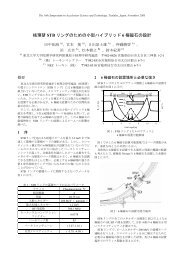
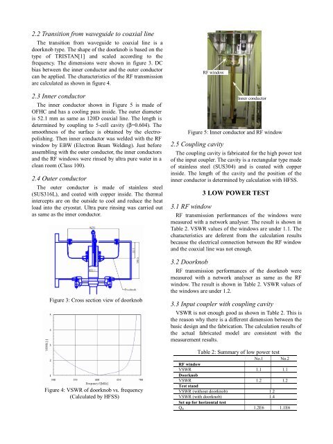
2.2 Transition from waveguide to coaxial line<br />
The transition from waveguide to coaxial line is a<br />
doorknob type. The shape of the doorknob is based on the<br />
type of TRISTAN[1] and scaled according to the<br />
frequency. The dimensions were shown in figure 3. DC<br />
bias between the inner conductor and the outer conductor<br />
can be applied. The characteristics of the RF transmission<br />
are calculated as shown in figure 4.<br />
2.3 Inner conductor<br />
The inner conductor shown in Figure 5 is made of<br />
OFHC and has a cooling pass inside. The outer diameter<br />
is 52.1 mm as same as 120D coaxial line. The length is<br />
determined by coupling to 5-cell cavity (β=0.604). The<br />
smoothness of the surface is obtained by the electropolishing.<br />
Then inner conductor was welded with the RF<br />
window by EBW (Electron Beam Welding). Just before<br />
assembling with the outer conductor, the inner conductors<br />
and the RF windows were rinsed by ultra pure water in a<br />
clean room (Class 100).<br />
2.4 Outer conductor<br />
The outer conductor is made of stainless steel<br />
(SUS316L), and coated with copper inside. The thermal<br />
intercepts are on the outside to cool and reduce the heat<br />
load into the cryostat. Ultra pure rinsing was carried out<br />
as same as the inner conductor.<br />
Figure 3: Cross section view of doorknob<br />
Figure 4: VSWR of doorknob vs. frequency<br />
(Calculated by HFSS)<br />
RF window<br />
Inner conductor<br />
Figure 5: Inner conductor and RF window<br />
2.5 Coupling cavity<br />
The coupling cavity is fabricated for the high power test<br />
of the input coupler. The cavity is a rectangular type made<br />
of stainless steel (SUS304) and is coated with copper<br />
inside. The length of the cavity and the position of the<br />
inner conductor is determined by calculation with HFSS.<br />
3 LOW POWER TEST<br />
3.1 RF window<br />
RF transmission performances of the windows were<br />
measured with a network analyser. The result is shown in<br />
Table 2. VSWR values of the windows are under 1.1. The<br />
characteristics are deferent from the calculation results<br />
because the electrical connection between the RF window<br />
and the coaxial line was not enough.<br />
3.2 Doorknob<br />
RF transmission performances of the doorknob were<br />
measured with a network analyser as same as the RF<br />
window. The result is shown in Table 2. VSWR values of<br />
the windows are under 1.2.<br />
3.3 Input coupler with coupling cavity<br />
VSWR is not enough good as shown in Table 2. This is<br />
the reason why there is a different dimension between the<br />
basic design and the fabrication. The calculation results of<br />
the actual fabricated model are consistent with the<br />
measurement results.<br />
Table 2: Summary of low power test<br />
No.1 No.2<br />
RF window<br />
VSWR 1.1 1.1<br />
Doorknob<br />
VSWR 1.2 1.2<br />
Test stand<br />
VSWR (without doorknob) 1.2<br />
VSWR (with doorknob) 1.4<br />
Set up for horizontal test<br />
Qin 1.2E6 1.1E6