
Create successful ePaper yourself
Turn your PDF publications into a flip-book with our unique Google optimized e-Paper software.
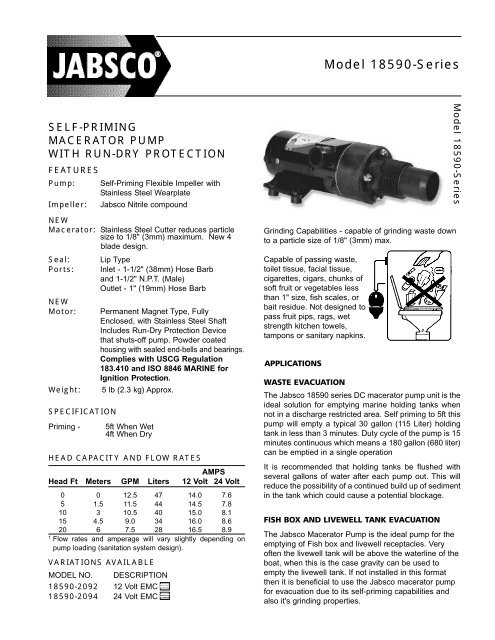
SELF-PRIMING<br />
MACERATOR PUMP<br />
WITH RUN-DRY PROTECTION<br />
FEATURES<br />
Pump: Self-Priming Flexible Impeller with<br />
Stainless Steel Wearplate<br />
Impeller: Jabsco Nitrile compound<br />
NEW<br />
Macerator: Stainless Steel Cutter reduces particle<br />
size to 1/8" (3mm) maximum. New 4<br />
blade design.<br />
Seal: Lip Type<br />
Ports: Inlet - 1-1/2" (38mm) Hose Barb<br />
and 1-1/2" N.P.T. (Male)<br />
Outlet - 1" (19mm) Hose Barb<br />
NEW<br />
Motor: Permanent Magnet Type, Fully<br />
Enclosed, with Stainless Steel Shaft<br />
Includes Run-Dry Protection Device<br />
that shuts-off pump. Powder coated<br />
housing with sealed end-bells and bearings.<br />
Complies with USCG Regulation<br />
183.410 and ISO 8846 MARINE for<br />
Ignition Protection.<br />
Weight: 5 lb (2.3 kg) Approx.<br />
SPECIFICATION<br />
Priming - 5ft When Wet<br />
4ft When Dry<br />
HEAD CAPACITY AND FLOW RATES<br />
AMPS<br />
Head Ft Meters GPM Liters 12 Volt 24 Volt<br />
0 0 12.5 47 14.0 7.6<br />
5 1.5 11.5 44 14.5 7.8<br />
10 3 10.5 40 15.0 8.1<br />
15 4.5 9.0 34 16.0 8.6<br />
20 6 7.5 28 16.5 8.9<br />
† Flow rates and amperage will vary slightly depending on<br />
pump loading (sanitation system design).<br />
VARIATIONS AVAILABLE<br />
MODEL NO. DESCRIPTION<br />
<strong>18590</strong>-2092 12 Volt EMC<br />
<strong>18590</strong>-2094 stScript 24 Volt EMC<br />
stScript Pict<br />
CE LOGO EP<br />
Pict<br />
CE LOGO EP<br />
<strong>Model</strong> <strong>18590</strong>-<strong>Series</strong><br />
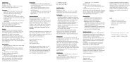
Grinding Capabilities - capable of grinding waste down<br />
to a particle size of 1/8" (3mm) max.<br />
Capable of passing waste,<br />
toilet tissue, facial tissue,<br />
cigarettes, cigars, chunks of<br />
soft fruit or vegetables less<br />
than 1" size, fish scales, or<br />
bait residue. Not designed to<br />
pass fruit pips, rags, wet<br />
strength kitchen towels,<br />
tampons or sanitary napkins.<br />
APPLICATIONS<br />
<strong>Model</strong> <strong>18590</strong>-<strong>Series</strong><br />
WASTE EVACUATION<br />
The Jabsco <strong>18590</strong> series DC macerator pump unit is the<br />
ideal solution for emptying marine holding tanks when<br />
not in a discharge restricted area. Self priming to 5ft this<br />
pump will empty a typical 30 gallon (115 Liter) holding<br />
tank in less than 3 minutes. Duty cycle of the pump is 15<br />
minutes continuous which means a 180 gallon (680 liter)<br />
can be emptied in a single operation<br />
It is recommended that holding tanks be flushed with<br />
several gallons of water after each pump out. This will<br />
reduce the possibility of a continued build up of sediment<br />
in the tank which could cause a potential blockage.<br />
FISH BOX AND LIVEWELL TANK EVACUATION<br />
The Jabsco Macerator Pump is the ideal pump for the<br />
emptying of Fish box and livewell receptacles. Very<br />
often the livewell tank will be above the waterline of the<br />
boat, when this is the case gravity can be used to<br />
empty the livewell tank. If not installed in this format<br />
then it is beneficial to use the Jabsco macerator pump<br />
for evacuation due to its self-priming capabilities and<br />
also it's grinding properties.
Fish boxes are typically mounted into the floor of the<br />
vessel and are very often below the waterline or only<br />
partially above the waterline. Again the Jabsco<br />
Macerator pump has the characteristics that lend<br />
themselves to this application. The bait residue<br />
particles of ice, fish scales and anything else that<br />
could potentially be found in the Fish-Box will be easily<br />
passed buy the Jabsco Macerator Pump, and the self<br />
priming capabilities are perfect for fish box installations<br />
common to many of today's sports fishing boats.<br />
GENERAL INSTALLATION SUGGESTIONS<br />
The pump can be mounted in any orientation without<br />
loss of performance. It is however recommended that if<br />
the pump is mounted vertically then the pump head be<br />
mounted below the motor (pump head facing downwards)<br />
Use the rubber grommets provided to absorb vibration<br />
The Macerator pump can be screwed directly into a<br />
1-1/2" (38mm) NPT tank flange or female pipe fitting.<br />
If attaching the inlet port to a pipe fitting it may require<br />
removal of the hose barbed port, this can be done<br />
using a hacksaw. Wrap port threads with a couple of<br />
wraps of Teflon tape and screw the pump assembly<br />
into the pipe fitting. Tighten hand tight, do not over<br />
tighten.<br />
Please Note: An air leak anywhere in the suction side<br />
of the plumbing system can cause extended dry<br />
running. All suction connections must be air tight and<br />
free of sharp bends or restrictions. If a deck fitting is<br />
installed for dockside pump-out and connected to the<br />
suction hose of the macerator by means of a tee fitting<br />
(without a Y-Valve), it too must be air tight to ensure<br />
proper priming.<br />
Use minimum 1" (19mm) ID hose for discharge and<br />
connect to thru-hull fitting located approximately 4-6<br />
inches above waterline.<br />
NOTICE: The discharge thru-hull may be positioned<br />
below the waterline only if the discharge hose has a<br />
vented loop fitting installed at least 8" above the waterline<br />
at all angles of heel or trim. Consult with a qualified<br />
marine plumber.<br />
INSTALLATION FOR WASTE APPLICATIONS<br />
Although the Jabsco Macerator pump can be installed<br />
at any convenient point in the waste discharge system,<br />
it is recommended that it be installed as close to the<br />
holding tank as possible, this will increase the performance<br />
of the pump. It is also recommended that the<br />
switch used to control the macerator be mounted close<br />
enough to the pump that it can be heard whilst in operation,<br />
this will allow the operator to hear a change in<br />
pump noise when the unit has finished pumping the<br />
tank dry. The pump then should be turned off; this will<br />
further increase the life of the pump.<br />
INSTALLATION FOR FISH BOX AND LIVEWELL<br />
APPLICATIONS<br />
As with the waste application the Jabsco Macerator<br />
Pump can be installed at any convenient point between<br />
the fishbox/livewell receptacle and the discharge port. It<br />
is recommended that it be installed as close to the tank<br />
as possible, this will increase the performance of the<br />
pump. It is also recommended that the switch used to<br />
control the macerator be mounted close enough to the<br />
pump that it can be heard whilst in operation, this will<br />
allow the operator to hear a change in pump noise<br />
when the unit has finished pumping the tank dry. The<br />
pump then should be turned off; this will further<br />
increase the life of the pump.<br />
ELECTRICAL<br />
Wire the unit in an Independent Circuit<br />
Consult the wiring table for fuse and wire size<br />
Consult the wiring diagram for connections<br />
WIRING TABLE<br />
AMP FUSE WIRE SIZE PER FEET OF RUN*<br />
VOLTAGE DRAW SIZE 0’-10’ 10’-15’ 15’-25’ 25’-40’ 40’-60’<br />
12 Vdc 16 20 #16(1.5) #14(2.5) #14(2.5) #12(4) #6(16)<br />
24 Vdc 8 15 #18(1) #16(1.5) #16(1.5) #14(2.5)#10(6)<br />
* Length of run is total length of the circuit from the power source to product and back to ground. Wire sizes<br />
listed are SAE guage and metric millimeters.<br />
Wiring Diagram<br />
Battery<br />
Fuse<br />
Waste<br />
Holding<br />
Master Switch
EXPLODED VIEW<br />
PARTS LIST<br />
Part<br />
Key Description Qty. Number<br />
1 Acorn Nut 4 91085-0340<br />
2 Fiber Washer* 4 91613-0140<br />
3 Stud* 2 17288-0010<br />
4 Macerator Housing 1 18594-1000<br />
5 Chopper Plate with Locknut 1 37056-2000<br />
6 Wearplate, Large 1 18597-1000<br />
7 Gaskets (2 each per kit)* 1 18596-1000<br />
8 Impeller* 1 6303-0003<br />
9 Wearplate, Small 1 12316-1002<br />
10 Body* 1 18593-1000<br />
11 Seal* 1 1040-0000<br />
12 Slinger 1 6342-0000<br />
13 Stud 2 17288-0000<br />
14 Motor 12 Volt 1 17246-1012<br />
Motor 24 Volt 1 17246-1024<br />
15 Grommets (Set of 4) 1 92900-0120<br />
Service Kit 1 18598-1000<br />
*These parts are supplied in 18598-1000 Service Kit.<br />
DISASSEMBLY<br />
Notice: Before performing any service, disconnect the electrical<br />
power to the macerator and take precaution to ensure that it is not<br />
restored until service is complete.<br />
Remove the four acorn nuts (Key 1) and fiber washers (Key 2) from<br />
the pump studs (Key 3). Slide the macerator housing (Key 4) off the<br />
studs. Insert a thin bladed 9/32" (7mm) ignition wrench behind the<br />
chopper plate (Key 5) and onto the flat of the motor shaft to prevent<br />
it from turning. Unscrew (counter-clockwise) the locknut on the end<br />
of the motor shaft and remove the stainless steel chopper blade. ††<br />
On new model macerators the shaft can be prevented from turning<br />
by inserting a screwdriver in the slot of the motor shaft extending<br />
from the motor’s rear end bell. Remove the pump wearplate<br />
(Key 6) and two paper gaskets (Key 7). Now slide the pump<br />
body (Key 10) with impeller (Key 8), small wearplate (Key 9), two<br />
studs and shaft seal as an assembly off the motor shaft and<br />
remaining two mounting studs.<br />
Remove the starlock retaining washer on the seal and push the<br />
seal out of the seal bore.<br />
Notice: If reconditioning pump with a service kit (Part No. 18598-<br />
1000), it is not necessary to remove the seal because the new seal<br />
is pre-installed in the new body. It is also generally not necessary<br />
to remove the slinger or brass studs screwed into the motor end<br />
bell.<br />
ASSEMBLY<br />
If installing a new seal, push it into the seal bore of the<br />
body with the lip pointing toward the impeller bore. Press<br />
the starlock washer into the seal bore with the concave<br />
side up to secure the seal in the bore. Install the two<br />
shorter studs in the two holes with threaded inserts in the<br />
new pump body and tighten finger tight. If required,<br />
screw two longer studs into the tapped holes in the<br />
motor end bell. Slide the new pump body with the shaft<br />
seal installed onto the motor shaft and two long mounting<br />
studs in the motor. Slide the small wearplate over the<br />
motor shaft and position it in the bottom of the impeller<br />
bore. Slide the new impeller onto the motor shaft and,<br />
with a counter-clockwise motion, push it into the pump<br />
impeller bore. Position one new gasket on the studs and<br />
against the pump body assuring the cut-out aligns with<br />
the inlet groove in the body. Reposition the large<br />
wearplate and second gasket on the studs and against<br />
the body; again, aligning the hole in the wearplate and<br />
gasket cut-out with the pump inlet. Position the chopper<br />
on the end of the motor shaft with drive tab aligned with<br />
flat of shaft and pointing toward the motor. Hold the shaft<br />
to prevent it from turning and secure the chopper to the<br />
shaft with the locknut. Position the macerator housing on<br />
the four studs ensuring the cut-out in the inner wall<br />
aligns with pump body inlet port and hole in the<br />
wearplate. Position a new fiber washer on each of the<br />
studs and secure the macerator housing in place with<br />
the four acorn nuts.<br />
†† On pumps manufactured prior to April of 1998, position a<br />
screwdriver between the prongs of the chopper and unscrew it<br />
(counter-clockwise) to remove it and its lock washer from the<br />
motor shaft.
DIMENSIONAL DRAWING<br />
Inches (Millimeters)<br />
TROUBLESHOOTING<br />
PUMP DOES NOT START:<br />
Impeller bound-up - Insert screwdriver in slot of<br />
shaft at motor’s rear end bell and rotate clockwise.<br />
No electrical power to pump or low voltage - With a<br />
voltage tester, check power to pump. The pump<br />
must have full voltage checked while pump is running.<br />
If it hasn’t started, see wire size recommendations<br />
and check for poor or corroded electrical connections.<br />
After long periods of nonuse, the flexible impeller may<br />
stick to the pump body preventing the macerator pump<br />
from turning freely. If this occurs, the impeller can be<br />
broken free by removing the rubber cap on the shaft at<br />
the rear end of the motor, inserting a screwdriver in the<br />
slot and rotating the shaft clockwise a quarter turn or<br />
more. When impeller is broken free, reinstall the plastic<br />
cap on the motor shaft.<br />
U.S.A.<br />
Jabsco<br />
Cape Ann Industrial Park<br />
Gloucester, MA 01930<br />
Tel: 978.281.0440<br />
Fax: 978.283.2619<br />
UNITED KINGDOM<br />
Jabsco<br />
Bingley Road, Hoddesdon<br />
Hertfordshire EN11 OBU<br />
Tel: +44 (0) 1992 450145<br />
Fax: +44 (0) 1992 467132<br />
CANADA<br />
Fluid Products Canada<br />
55 Royal Road<br />
Guelph, Ontario N1H 1T1<br />
Tel: (519) 821.1900<br />
Fax: (519) 821.2569<br />
PUMP RUNS BUT DOES NOT PUMP:<br />
Lack of priming - Check all plumbing connections<br />
to ensure they are airtight. If a waste deck plate is connected<br />
to pump suction hose by a “Tee” fitting, the<br />
deck plate must also be airtight.<br />
Worn impeller* - Replace flexible impeller.<br />
*A worn impeller may be a likely cause if the Run-Dry<br />
Protection Device has often been allowed to shut-off<br />
the pump.<br />
MOTOR ILLUSTRATION<br />
THE PRODUCTS DESCRIBED HEREIN ARE<br />
SUBJECT TO THE JABSCO ONE YEAR LIMITED<br />
WARRANTY, WHICH IS AVAILABLE FOR YOUR<br />
INSPECTION UPON REQUEST.<br />
JAPAN<br />
NHK Jabsco Company Ltd.<br />
3-21-10, Shin-Yokohama<br />
Kohoku-Ku, Yokohama, 222<br />
Tel: 045.475.8906<br />
Fax: 045.475.8908<br />
GERMANY<br />
Jabsco GmbH<br />
Oststrasse 28<br />
22840 Norderstedt<br />
Tel: +49-40-53 53 73 -0<br />
Fax: +49-40-53 53 73 -11<br />
© Copyright 2004, ITT Industries Printed in U.S.A. All Rights Reserved Form: 950-0141 Rev. 02/2004