5 - LISEGA
5 - LISEGA
5 - LISEGA

You also want an ePaper? Increase the reach of your titles
YUMPU automatically turns print PDFs into web optimized ePapers that Google loves.
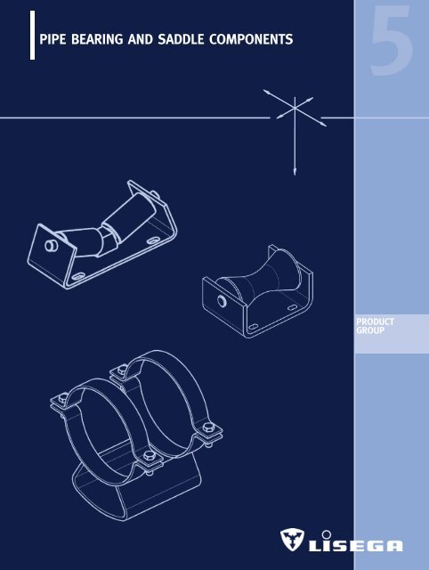
PIPE BEARING AND SADDLE COMPONENTS<br />
5<br />
PRODUCT<br />
GROUP
PIPE BEARINGS<br />
AND SADDLE COMPONENTS 5<br />
CONTENTS PAGE<br />
Roller bearings, type 51 to 53______________________________________ 5.1<br />
Cylinder roller bearings, type 51 .. 19 ______________________________ 5.3<br />
Double taper roller bearings, single, type 52 .. 19 ____________________ 5.3<br />
Double taper roller bearings, movable, type 52 .. 29 __________________ 5.3<br />
Double cylinder roller bearings, type 53 .. 19 ________________________ 5.4<br />
Double cylinder roller bearings, type 53 .. 29 ________________________ 5.4<br />
Pipe saddle for welding on, type 54 .. 19____________________________ 5.5<br />
Pipe saddle with pipe clamp, type 54 .. 29 __________________________ 5.5<br />
Support tray with pipe clamp, type 54 .. 39 __________________________ 5.6<br />
Lift-off restraint, type 55 .. 19 ______________________________________ 5.6<br />
Insulated pipe supports, type 56 __________________________________ 5.7<br />
Cold block pipe supports, type 56 ________________________________ 5.10<br />
Weld-on pipe shoes, type 57 .. 11 and 57 .. 12 ____________________ 5.11<br />
Stanchions for horizontal pipes, type 58 ..1. and 58 .. 2.______________ 5.12<br />
Stanchions for short radius elbows<br />
(R OD), type 58 .. 1. and 58 .. 2. ________________________________ 5.13<br />
Stanchions for long radius elbows<br />
(R 1.5OD), type 58 .. 1. and 58 .. 2. ______________________________ 5.14<br />
Stanchions, type 58 ____________________________________________ 5.15<br />
Elbow pads, type 58 .. 3. ________________________________________ 5.15<br />
0<br />
1<br />
2<br />
3<br />
4<br />
PRODUCT<br />
GROUP<br />
6<br />
7<br />
8<br />
9<br />
5.0<br />
5
5.1<br />
ROLLER BEARINGS<br />
TYPE 51 TO 53<br />
Piping systems arranged<br />
horizontally over long<br />
stretches are placed on<br />
supports. To allow normal<br />
thermal movement, the<br />
support points are designed<br />
as either sliding or roller<br />
types.<br />
For larger diameter piping<br />
and especially when fluids<br />
and insulation produce high<br />
loads, roller bearings provide<br />
the optimum solution.<br />
<strong>LISEGA</strong> – Standard Roller Bearings<br />
& Pipe Saddles<br />
These items are standardized in <strong>LISEGA</strong><br />
Product Group 5 for a wide range of applications.<br />
For applications outside the standard range,<br />
special designs can be offered.<br />
Specification and design of roller bearings<br />
In the design of standard components, practical<br />
requirements find special consideration.<br />
The standard roller bearing is hot-dip galvanized<br />
and provides optimum corrosion protection.<br />
Except for the movable double cylinder<br />
roller bearing Type 53 .. 29, weldings have<br />
been dispensed with.<br />
The bearing axles are made from austenitic<br />
material and have a polished surface.<br />
The slide bearings incorporate bushings made<br />
from a Teflon bronze sintered compound material<br />
fitted into the roller. The bearings are<br />
maintenance free and guarantee dry running<br />
qualities. The formed shoulder of each bushing<br />
minimizes the stick-slip drag effect on lateral<br />
loading. The bearing axles are permanently<br />
fixed in the middle section of the base. Special<br />
locking on the side bracket is not required.<br />
The rollers are made from high tensile carbon<br />
steel. Their outer surfaces are machined.<br />
To compensate for misaligned anchor bolts,<br />
on site, the base holes are slotted for additional<br />
adjustment.<br />
The height dimensions (E) within a load group<br />
range are identical for all roller bearings, including<br />
the lateral movement type.<br />
Information regarding material codes, standards,<br />
calculations and weldings are given<br />
in the Technical Specification on page 0.9<br />
and 0.10<br />
Manufacture and Storing<br />
For frequently used items, efficient serial production<br />
and stocking can be achieved through<br />
standardization.<br />
Modern order logistics is possible through a<br />
single fabrication process or in small lots,<br />
thus ensuring short fabrication and delivery<br />
times.<br />
Technical Data for Roller Bearings<br />
➜ rolling resistance of the rollers max 4%<br />
➜ rolling resistance on lateral movement<br />
max 4%<br />
➜ temperature range at nominal load<br />
-30°C to 80°C<br />
➜ permissible lateral loading 35% of<br />
nominal load<br />
➜ permissible lift-off load 10% of<br />
nominal load
INSTALLATION INSTRUCTIONS<br />
Roller Bearings<br />
The roller bearings can be fixed by simple<br />
bolt connections or welded to the contact<br />
surface of the pipe support. In each case the<br />
complete width of the base plate must be<br />
supported and secured.<br />
Due to the slotted holes, roller bearings can<br />
easily be adjusted even with slightly misaligned<br />
anchor bolts.<br />
Pipe Saddles<br />
Welded pipe saddles are supplied coated with<br />
a weldable primer (30µm) (see Technical<br />
Specification page 0.10).<br />
Care must be taken that the specified minimum<br />
weld size is applied.<br />
Pipe saddles with clamps are supplied ready<br />
to install.<br />
Care must be taken to ensure the correct positioning<br />
and adequate presetting of the bolts.<br />
Lift-off restraints<br />
When installing the lift-off restraint plate, care<br />
must be taken to ensure that the gap between<br />
plate and roller is sufficient for normal<br />
movement along the whole travel range.<br />
The special design and quality of manufacture<br />
provide the following application<br />
benefits:<br />
➜ maintenance of minimum roll<br />
resistance (max 4%)<br />
➜ takeover of realistic lateral loading<br />
for double taper and double cylinder<br />
roller bearings (35% of the support<br />
load)<br />
➜ whole support load can be carried<br />
by just one roller of the double<br />
cylinder type<br />
➜ absorption of lateral displacements by<br />
sideways sliding designs<br />
➜ simple and safe design of lift-off<br />
restraints<br />
➜ use of pipe saddles enables favorable<br />
load transfer into the pipe wall<br />
➜ design of pipe saddles minimizes<br />
heat transfer<br />
➜ hot dip galvanized corrosion protection<br />
for all roller bearings<br />
➜ maintenance free operation<br />
➜ stainless steel roller axle<br />
➜ Teflon bronze compound bushes<br />
➜ large range of sizes OD 60mm –<br />
OD 1350mm)<br />
➜ large load range (max support load<br />
120kN)<br />
➜ short support height (see selection<br />
chart for E dimension)<br />
5<br />
5.2
Single cylinder<br />
roller bearing<br />
type 51 08 19 to 51 35 19<br />
Order details:<br />
Type 51 .. 19<br />
Double taper roller bearing<br />
(single)<br />
type 52 04 19 to 52 35 19<br />
E = 1.064 · R +x<br />
Order details:<br />
Type 52 .. 19<br />
Double taper roller<br />
bearing (sideways movable)<br />
type 52 04 29 to 52 35 29<br />
E = 1.064 · R +x<br />
Order details:<br />
Type 52 .. 29<br />
5.3<br />
Type<br />
51 08 19<br />
51 16 19<br />
51 35 19<br />
Type<br />
52 04 19<br />
52 08 19<br />
52 16 19<br />
52 35 19<br />
Type<br />
52 04 29<br />
52 08 29<br />
52 16 29<br />
52 35 29<br />
Load FN<br />
(kN)<br />
8<br />
16<br />
35<br />
Load FN<br />
(kN)<br />
4<br />
8<br />
16<br />
35<br />
travel 50mm<br />
Load FN<br />
(kN)<br />
4<br />
8<br />
16<br />
35<br />
A1 A2 B E F G a b s<br />
90<br />
120<br />
145<br />
70<br />
100<br />
120<br />
80<br />
100<br />
130<br />
<br />
<br />
50<br />
60<br />
85<br />
35<br />
55<br />
60<br />
60<br />
75<br />
95<br />
20<br />
24<br />
26<br />
10<br />
12<br />
14<br />
5<br />
6<br />
10<br />
Weight<br />
(kg)<br />
1.2<br />
2.4<br />
5.5<br />
R A B C F G a b s x Weight<br />
E<br />
min.max.<br />
(kg)<br />
27 - 100 105 90 70 83 160 55 70 20 10 4 54 1.8<br />
84 - 130 135 100 85 153 202 75 75 20 10 6 64 3.3<br />
110 - 165 165 120 100 191 250 90 90 24 12 8 74 5.4<br />
136 - 230 230 160 135 247 347 130 120 26 14 12 102 14.0<br />
R A B C F G a b s x Weight<br />
E<br />
min.max.<br />
(kg)<br />
27 - 100 155 90 70 83 160 105 70 20 10 4 54 2.0<br />
84 - 130 185 100 85 153 202 120 75 20 10 6 64 3.6<br />
110 - 165 215 120 100 191 250 140 90 24 12 8 74 6.0<br />
136 - 230<br />
280 160 135 247 347 180 120 26 14 12 102 15.5
DOUBLE CYLINDER ROLLER BEARING<br />
TYPE 53<br />
Type<br />
53 08 19<br />
53 16 19<br />
53 35 19<br />
53 60 19<br />
53 12 19<br />
Type<br />
53 08 29<br />
53 16 29<br />
53 35 29<br />
53 60 29<br />
53 12 29<br />
Load FN<br />
(kN)<br />
8<br />
16<br />
35<br />
60<br />
120<br />
Load FN<br />
(kN)<br />
8<br />
16<br />
35<br />
60<br />
120<br />
R A1 A2 B C F G a b s x Weight<br />
E<br />
min.max.<br />
(kg)<br />
30 - 190 210 190 80 65 72 242 140 60 20 10 5 40 2.5<br />
85 - 310 310 285 100 90 135 375 230 75 24 12 6 45 5.5<br />
175 - 440 420 370 130 110 240 520 320 90 26 14 10 53 14.0<br />
250 - 520 490 430 150 135 329 615 370 100 31 18 12 63 23.0<br />
400 - 675 620 525 180 165 495 785 460 115 31 22 18 70 48.0<br />
A + travel s <br />
R A B C Ød F G H K t x Weight<br />
E<br />
min.max.<br />
(kg)<br />
30 - 190 260 210 50 10 72 242 145 165 65 60 5 40 6<br />
85 - 310 350 300 50 12 135 375 160 185 90 75 5 45 10<br />
175 - 440 475 410 60 14 240 520 215 245 110 100 6 53 23<br />
250 - 520 530 465 70 18 329 615 250 290 130 120 8 63 35<br />
400 - 675 700 635 80 23 495 785<br />
315 360 160 145 10 70 70<br />
5<br />
Double cylinder roller<br />
bearing<br />
type 53 08 19 to 53 12 19<br />
E = 1.064 · R+x<br />
Order details:<br />
Type 53 .. 19<br />
Double cylinder roller<br />
bearing (sideways movable)<br />
type 53 08 29 to 53 12 29<br />
E = 1.064 · R+x<br />
Travel s= 100…600mm<br />
Centre fixing point from<br />
Travel s= 300mm<br />
Weight at s= 100mm<br />
Order details:<br />
Type 53 .. 29<br />
with s = ... mm<br />
5.4
5.5<br />
WELD-ON PIPE SADDLES<br />
TYPE 54<br />
Weld-on pipe saddle<br />
type 54 06 19 to 54 81 19<br />
Load at pipe<br />
temperature 150°C.<br />
Order details:<br />
Type 54 .. 19<br />
R = ... mm<br />
Pipe saddle with<br />
pipe clamp<br />
type 54 06 29 to 54 81 29<br />
Load at pipe<br />
temperature 150°C.<br />
Order details:<br />
Type 54 .. 29<br />
R = ... mm<br />
Up to<br />
OD 406.4<br />
Type<br />
54 06 19<br />
54 08 19<br />
54 09 19<br />
54 11 19<br />
54 14 19<br />
54 17 19<br />
54 19 19<br />
54 22 19<br />
54 27 19<br />
54 32 19<br />
54 36 19<br />
54 41 19<br />
54 51 19<br />
54 61 19<br />
54 71 19<br />
54 81 19<br />
Up to<br />
OD 406.4<br />
Type<br />
54 06 29<br />
54 08 29<br />
54 09 29<br />
54 11 29<br />
54 14 29<br />
54 17 29<br />
54 19 29<br />
54 22 29<br />
54 27 29<br />
54 32 29<br />
54 36 29<br />
54 41 29<br />
54 51 29<br />
54 61 29<br />
54 71 29<br />
54 81 29<br />
OD<br />
Load FN<br />
(kN) <br />
1.4<br />
1.4<br />
1.4<br />
1.8<br />
4<br />
4<br />
5<br />
8<br />
12<br />
20<br />
20<br />
38<br />
50<br />
65<br />
100<br />
120<br />
OD<br />
Load FN<br />
(kN) <br />
1.4<br />
1.4<br />
1.4<br />
1.8<br />
4<br />
4<br />
5<br />
8<br />
12<br />
20<br />
20<br />
38<br />
50<br />
65<br />
100<br />
120<br />
From<br />
OD 508<br />
OD<br />
60.3<br />
76.1<br />
88.9<br />
114.3<br />
139.7<br />
168.3<br />
193.7<br />
219.1<br />
273<br />
323.9<br />
355.6<br />
406.4<br />
508<br />
609.6<br />
711.2<br />
812.8<br />
From<br />
OD 508<br />
OD<br />
60.3<br />
76.1<br />
88.9<br />
114.3<br />
139.7<br />
168.3<br />
193.7<br />
219.1<br />
273<br />
323.9<br />
355.6<br />
406.4<br />
508<br />
609.6<br />
711.2<br />
812.8<br />
OD<br />
OD<br />
R<br />
R<br />
80 - 180<br />
90 - 190<br />
95 - 195<br />
110 - 210<br />
120 - 220<br />
135 - 235<br />
150 - 250<br />
160 - 260<br />
190 - 290<br />
215 - 315<br />
230 - 330<br />
255 - 355<br />
325 - 415<br />
375 - 465<br />
430 - 520<br />
480 - 570<br />
80 - 180<br />
90 - 190<br />
95 - 195<br />
110 - 210<br />
120 - 220<br />
135 - 235<br />
150 - 250<br />
160 - 260<br />
190 - 290<br />
215 - 315<br />
230 - 330<br />
255 - 355<br />
325 - 415<br />
375 - 465<br />
430 - 520<br />
480 - 570<br />
B<br />
L=300<br />
a s<br />
3<br />
3<br />
3<br />
3<br />
3<br />
3<br />
3<br />
4<br />
4<br />
4<br />
4<br />
5<br />
5<br />
5<br />
6<br />
6<br />
40<br />
40<br />
40<br />
50<br />
50<br />
50<br />
50<br />
50<br />
60<br />
60<br />
60<br />
70<br />
70<br />
90<br />
90<br />
90<br />
L=300<br />
3<br />
3<br />
3<br />
3<br />
4<br />
5<br />
5<br />
6<br />
10<br />
12<br />
12<br />
15<br />
10<br />
12<br />
15<br />
20<br />
s<br />
3<br />
3<br />
3<br />
3<br />
4<br />
5<br />
5<br />
6<br />
10<br />
12<br />
12<br />
15<br />
10<br />
12<br />
15<br />
20<br />
Weight<br />
(kg)<br />
1.4 - 3.5<br />
1.5 - 3.7<br />
1.5 - 3.8<br />
1.5 - 4.0<br />
2.0 - 5.0<br />
3.0 - 6.5<br />
3.0 - 6.8<br />
4.0 - 8.0<br />
6.7 - 13.5<br />
9.6 - 18<br />
10 - 18<br />
13 - 25<br />
10 - 16<br />
12 - 21<br />
16 - 26<br />
19 - 33<br />
Weight<br />
(kg)<br />
2.5 - 4.8<br />
2.8 - 5.8<br />
3.1 - 6.0<br />
5 - 7<br />
6 - 9<br />
7 -12<br />
8 -13<br />
9 -15<br />
15 - 20<br />
19 - 26<br />
21 - 30<br />
30 - 40<br />
32 - 38<br />
63 - 72<br />
75 - 86<br />
84 - 98
PIPE TRAY WITH PIPE CLAMPS TYPE 54<br />
LIFT-OFF RESTRAINT TYPE 55<br />
Type<br />
54 06 39<br />
54 08 39<br />
54 09 39<br />
54 11 39<br />
54 14 39<br />
54 17 39<br />
54 19 39<br />
54 22 39<br />
54 27 39<br />
54 32 39<br />
54 36 39<br />
54 41 39<br />
54 51 39<br />
54 61 39<br />
54 71 39<br />
54 81 39<br />
Type<br />
55 08 19<br />
55 16 19<br />
55 35 19<br />
55 60 19<br />
55 12 19<br />
OD<br />
Load FN<br />
(kN)<br />
0.8<br />
0.8<br />
1.2<br />
1.5<br />
4.0<br />
4.0<br />
5.0<br />
8.0<br />
10<br />
15<br />
20<br />
35<br />
40<br />
60<br />
80<br />
100<br />
90˚<br />
compatible with<br />
roller bearing, type<br />
53 08 19<br />
53 16 19<br />
53 35 19<br />
53 60 19<br />
53 12 19<br />
OD<br />
OD<br />
60.3<br />
76.1<br />
88.9<br />
114.3<br />
139.7<br />
168.3<br />
193.7<br />
219.1<br />
273.0<br />
323.9<br />
355.6<br />
406.4<br />
508.0<br />
609.6<br />
711.2<br />
812.8<br />
R<br />
L=300<br />
L=300<br />
A B R<br />
226<br />
335<br />
455<br />
560<br />
700<br />
34<br />
41<br />
48<br />
62<br />
75<br />
90<br />
102<br />
116<br />
143<br />
170<br />
188<br />
214<br />
264<br />
317<br />
370<br />
421<br />
80<br />
100<br />
130<br />
150<br />
180<br />
s<br />
3<br />
3<br />
5<br />
5<br />
5<br />
5<br />
5<br />
6<br />
6<br />
8<br />
10<br />
10<br />
10<br />
12<br />
15<br />
15<br />
Weight<br />
(kg)<br />
1.7<br />
2.0<br />
2.6<br />
4.7<br />
5.4<br />
5.9<br />
6.6<br />
7.5<br />
11<br />
14<br />
16<br />
24<br />
28<br />
56<br />
68<br />
75<br />
30 - 190<br />
85 - 310<br />
175 - 440<br />
250 - 520<br />
400 - 675<br />
5<br />
Pipe tray with pipe clamps<br />
type 54 06 39 to 54 81 39<br />
Order details:<br />
Type 54 .. 39<br />
Lift-off restraint<br />
type 55 08 19 to 55 12 19<br />
Order details:<br />
Type 55 .. 19<br />
for type 54 .. .9<br />
R = ... mm<br />
5.6
5.7<br />
INSULATED PIPE SUPPORTS<br />
TYPE 56<br />
Pipe Supports for Cryogenic Applications<br />
<strong>LISEGA</strong> offer a complete range of insulated<br />
pipe supports for all types of cryogenic piping<br />
applications. Typically, these include industrial<br />
processes involving the production, transportation<br />
and distribution of liquefied gases<br />
including methane, propane, butane (LNG),<br />
ethylene, oxygen, nitrogen and ammonia (LPG).<br />
<strong>LISEGA</strong> standard insulated pipe supports are<br />
designed in accordance with recognized engineering<br />
specifications and international standards<br />
for pipes ranging in size from OD<br />
21.3mm to OD 914mm with insulation thicknesses<br />
from 25mm up to 250mm. The supports<br />
are manufactured using materials suitable<br />
for the loads specified and for temperatures<br />
ranging from ambient to –196°C.<br />
Insulation Material<br />
The insulation material that<br />
forms an integral part of the insulated<br />
pipe support assembly is manufactured<br />
using fire-retarding high-density polyurethane<br />
(PUF) foam. For the supply of the PUF components<br />
and consumables, <strong>LISEGA</strong> have<br />
formed an alliance with Bains Harding<br />
Industries Pty. Ltd., Australia. With more than<br />
twenty five years experience in industrial<br />
insulation, the company has extensive<br />
experience in the manufacture of rigid<br />
polyurethane insulation materials including<br />
highdensity moulded products and provide<br />
construction and maintenance services to<br />
the liquefied natural gas industry (LNG) in<br />
Australia and South East Asia.<br />
PUF Manufacture<br />
The PUF is monolithically molded in heavy<br />
duty steel molds under carefully controlled<br />
temperature and humidity conditions. This<br />
ensures compliance with dimensional specifications<br />
and provides clean, sharp edges<br />
that fit neatly with the adjacent line insulation<br />
material on site. Careful attention is<br />
given to the curing of the PUF after molding<br />
to ensure dimensional stability.<br />
Both single and multilayer PUF cradle<br />
systems are manufactured in accordance<br />
with ASTM C-585 and incorporate stepped<br />
radial and offset longitudinal joints. This provides<br />
a reliable interlocking interface with<br />
each layer of the adjacent line insulation on<br />
site and prevents a direct vapor path to the<br />
insulation surface.<br />
All exposed PUF cradle surfaces are sealed<br />
with cryogenic fire-retarding elastomeric vapor<br />
barrier mastic to prevent moisture ingress.<br />
A laminated aluminum/polyester foil is bonded<br />
to the outermost surface of the PUF<br />
cradle assembly. This has an overlap allowance<br />
designed to cover the adjacent line<br />
insulation material on site. Finally, a sheet<br />
metal jacket forms part of the PUF cradle<br />
assembly and fits over the aluminum/polyester<br />
foil to provide additional support and<br />
insulation protection.<br />
The PUF cradles are available in three standard<br />
densities to provide for varying load<br />
requirements –<br />
160 kg/m 3 ,<br />
224 kg/m 3 ,<br />
320 kg/m 3 .
Steel Clamp Base<br />
<strong>LISEGA</strong> standard insulated pipe supports are<br />
designed to clamp onto the pipe mechanically.<br />
The steel clamp base support that the PUF<br />
cradle assembly fits into is manufactured<br />
from carbon steel and supplied with a hot<br />
dip galvanized finish as standard.<br />
Material grades, welding and surface treatment<br />
are in accordance with the <strong>LISEGA</strong> standard<br />
specifications shown on pages 0.9 and 0.10<br />
of the catalog.<br />
The quality control system employed by <strong>LISEGA</strong><br />
in the manufacture and assembly of pipe<br />
supports is described on page 0.15. The inspection<br />
and test procedure includes a trial<br />
fitting of each pipe support to a suitable<br />
section of pipe to ensure compliance with<br />
the specification.<br />
Density<br />
Compressive strength<br />
Linear coefficient of<br />
expansion<br />
Closed cell content<br />
Thermal conductivity<br />
Nominal thickness<br />
of insulation<br />
80<br />
100<br />
130<br />
150<br />
180<br />
200<br />
250<br />
20°C<br />
-165°C<br />
20°C<br />
-165°C<br />
Material properties of the insulation<br />
Unit<br />
kg/m 3<br />
MPa<br />
MPa<br />
1/K<br />
%<br />
W/mK<br />
W/mK<br />
Thickness<br />
of the layering<br />
40 / 40<br />
50 / 50<br />
30 / 50 / 50<br />
50 / 50 / 50<br />
50 / 80 / 50<br />
50 / 100 / 50<br />
50 / 50 / 100 / 50<br />
Test<br />
standard<br />
ASTM<br />
D1622<br />
ASTM<br />
D1621<br />
BS 4370<br />
ASTM<br />
D2856<br />
ASTM<br />
C177<br />
160<br />
2.0<br />
3.675<br />
70x10 -6<br />
90<br />
0.032<br />
0.021<br />
5<br />
224<br />
4.0<br />
5.75<br />
70x10 -6<br />
90<br />
0.035<br />
0.027<br />
320<br />
7.0<br />
12.25<br />
70x10 -6<br />
90<br />
0.041<br />
0.034<br />
5.8
CRYOGENIC CLAMP BASES<br />
TYPE 56 .. 10 TO 56 .. 69<br />
Cryogenic clamp bases<br />
Type 56 01 10 to 56 91 69<br />
D<br />
75 … 230<br />
230 … 300<br />
300 … 450<br />
450 … 600<br />
600 … 800<br />
800<br />
Type<br />
56 01 ..<br />
56 02 ..<br />
56 03 ..<br />
56 06 ..<br />
56 09 ..<br />
56 11 ..<br />
56 17 ..<br />
56 22 ..<br />
56 27 ..<br />
56 32 ..<br />
56 36 ..<br />
56 41 ..<br />
56 46 ..<br />
56 51 ..<br />
56 56 ..<br />
56 61 ..<br />
56 66 ..<br />
56 71 ..<br />
56 76 ..<br />
56 81 ..<br />
56 91 ..<br />
5.9<br />
OD<br />
21.3<br />
26.9<br />
33.7<br />
60.3<br />
88.9<br />
114.3<br />
168.3<br />
219.1<br />
273.0<br />
323.9<br />
355.6<br />
406.4<br />
457.2<br />
508.0<br />
558.8<br />
609.6<br />
660.4<br />
711.2<br />
762.0<br />
812.8<br />
914.4<br />
Width of the<br />
clamp base B<br />
100<br />
150<br />
200<br />
300<br />
400<br />
500<br />
Maximum lateral loading 30% of vertical load<br />
Table of outer diameter D of the insulation (excluding sheet metal jacket)<br />
Nominal insulation thickness<br />
25 40 50 80 100 130 150 180 200<br />
71<br />
77<br />
84<br />
110<br />
139<br />
164<br />
218<br />
269<br />
323<br />
56 .. .0<br />
101<br />
107<br />
114<br />
140<br />
169<br />
194<br />
248<br />
199<br />
353<br />
404<br />
56 .. .1<br />
121 181 221<br />
127 187 227 287<br />
134 194 234 294<br />
160 220 260 320<br />
189 249 289 349<br />
214 274 314 374<br />
268 328 368 428<br />
319 379 419 479<br />
373 433 473 533<br />
424 484 524 584<br />
456 516 556 616<br />
566 606 666<br />
657 717<br />
708 768<br />
759 918<br />
810 870<br />
860 920<br />
911 971<br />
962 1022<br />
1013 1073<br />
1114 1174<br />
6th digit of type designation<br />
56 .. .2 56 .. .3 56 .. .4 56 .. .5<br />
360<br />
689<br />
414<br />
468<br />
519<br />
573<br />
624<br />
659<br />
706<br />
757<br />
808<br />
859<br />
910<br />
960<br />
1011<br />
1062<br />
1113<br />
1214<br />
56 .. .6<br />
OD<br />
449<br />
474<br />
528<br />
579<br />
633<br />
684<br />
716<br />
766<br />
817<br />
868<br />
919<br />
970<br />
1020<br />
1071<br />
1122<br />
1173<br />
1274<br />
56 .. .7<br />
.. .. 1. Length C: 300; density of insulation 160kg/m 3<br />
.. .. 2. Length C: 500; density of insulation 160kg/m 3<br />
.. .. 4. Length C: 500; density of insulation 224kg/m 3<br />
.. .. 6. Length C: 500; density of insulation 320kg/m 3<br />
150<br />
100<br />
50<br />
sheet metal jacket<br />
C minus 20<br />
514<br />
568<br />
619<br />
673<br />
724<br />
756<br />
806<br />
857<br />
908<br />
959<br />
1010<br />
1060<br />
1111<br />
1162<br />
1213<br />
1314<br />
56 .. .8<br />
250<br />
614<br />
668<br />
719<br />
773<br />
824<br />
856<br />
906<br />
957<br />
1008<br />
1059<br />
1110<br />
1160<br />
1211<br />
1262<br />
1313<br />
1414<br />
56 .. .9<br />
160<br />
Permissible load (kN) at –170°C <br />
2.3 2.3<br />
2.9 2.9<br />
3.7 3.7<br />
6.7 6.7<br />
9.8 9.8<br />
12 21<br />
18 31<br />
24 40<br />
30 50<br />
36 60<br />
39 65 105<br />
45 75 120<br />
50 84 135<br />
56 94 150 265<br />
62 100 165 290<br />
67 110 180 320<br />
73 120 195 345<br />
79 130 210 370<br />
84 140 225 400<br />
90 150 240 425<br />
100 165 275 480<br />
5th digit of type designation<br />
56 .. 1. 56 .. 2. 56 .. 4. 56 .. 6.
COLD BLOCK PIPE SUPPORTS<br />
TYPE 56 .. 91<br />
Pipe Supports for Cryogenic Applications<br />
<strong>LISEGA</strong> standard cold block supports are designed<br />
in accordance with recognized engineering<br />
specifications and international standards<br />
for pipes ranging in size from OD 21.3mm<br />
to OD 914mm. The supports are manufactured<br />
using materials that are suitable for the loads<br />
specified and temperatures ranging from<br />
ambient to –196°C.<br />
Cold Block Material<br />
The cold block insulation material forming<br />
an integral part of the cold block pipe support<br />
assembly is designed to provide a sufficient<br />
thermal insulation barrier between the pipe<br />
operating at subzero temperatures and the<br />
supporting structure that is at ambient temperature.<br />
<strong>LISEGA</strong> standard cold block supports incorporate<br />
Lignostone ® densified wood blocks<br />
that are manufactured from selected beech<br />
veneers, impregnated under vacuum with<br />
thermosetting synthetic resin and densified<br />
under heat and pressure. The Lignostone ®<br />
blocks combine high strength with low thermal<br />
conductivity, have proven cryogenic<br />
capability and are used exclusively for cold<br />
pipe applications throughout the world.<br />
Alternative cold block insulation materials<br />
suitable for cryogenic applications are available<br />
on request.<br />
Type<br />
56 01 91<br />
56 02 91<br />
56 03 91<br />
56 06 91<br />
56 09 91<br />
56 11 91<br />
56 17 91<br />
56 22 91<br />
56 27 91<br />
56 32 91<br />
56 36 91<br />
56 41 91<br />
56 46 91<br />
56 51 91<br />
56 56 91<br />
56 61 91<br />
56 66 91<br />
56 71 91<br />
56 76 91<br />
56 81 91<br />
56 91 91<br />
OD<br />
21.3<br />
26.9<br />
33.7<br />
60.3<br />
88.9<br />
114.3<br />
168.3<br />
219.1<br />
273.0<br />
323.9<br />
355.6<br />
406.4<br />
457.2<br />
508.0<br />
558.8<br />
609.6<br />
660.4<br />
711.2<br />
762.0<br />
812.8<br />
914.4<br />
permissible<br />
load in kN <br />
1.3<br />
1.6<br />
2.1<br />
3.7<br />
5.5<br />
7.1<br />
10<br />
13<br />
17<br />
20<br />
22<br />
25<br />
28<br />
31<br />
34<br />
38<br />
41<br />
44<br />
47<br />
50<br />
57<br />
Steel Clamp Bases<br />
<strong>LISEGA</strong> standard cold block pipe supports are<br />
designed to mechanically clamp onto the pipe.<br />
The steel clamp base support is manufactured<br />
from stainless steel and is supplied self-color<br />
as standard. The cold block is bolted between<br />
the underside of the clamp base and a carbon<br />
steel base plate. Material grades, welding and<br />
surface treatment are in accordance with the<br />
<strong>LISEGA</strong> standard specifications.<br />
Other pipe support configurations can be supplied<br />
(pipe support stanchions, cradles, anchors)<br />
on request.<br />
<strong>LISEGA</strong> cold block pipe supports are supplied<br />
with detailed installation instructions. Each pipe<br />
support is clearly marked in accordance with<br />
the <strong>LISEGA</strong> Type Designation System.<br />
<strong>LISEGA</strong> cold block pipe supports are supplied<br />
fully assembled and packed to protect the finished<br />
product from superficial damage and moisture<br />
ingress during storage and transportation.<br />
Temperature °C<br />
Thermal<br />
conductivity W / (Km)<br />
A B H E G<br />
175<br />
175<br />
175<br />
175<br />
175<br />
175<br />
175<br />
240<br />
240<br />
360<br />
360<br />
360<br />
410<br />
440<br />
490<br />
490<br />
590<br />
590<br />
590<br />
590<br />
690<br />
200<br />
200<br />
200<br />
200<br />
200<br />
200<br />
200<br />
200<br />
200<br />
400<br />
400<br />
400<br />
400<br />
400<br />
400<br />
400<br />
400<br />
400<br />
400<br />
400<br />
400<br />
100<br />
100<br />
100<br />
100<br />
100<br />
150<br />
150<br />
150<br />
150<br />
150<br />
150<br />
150<br />
150<br />
150<br />
150<br />
150<br />
150<br />
150<br />
150<br />
150<br />
150<br />
111<br />
113<br />
117<br />
130<br />
144<br />
207<br />
234<br />
260<br />
287<br />
312<br />
328<br />
353<br />
379<br />
404<br />
429<br />
455<br />
480<br />
506<br />
531<br />
556<br />
607<br />
+20<br />
0.309<br />
73<br />
80<br />
84<br />
117<br />
139<br />
183<br />
223<br />
258<br />
315<br />
354<br />
375<br />
438<br />
477<br />
528<br />
598<br />
640<br />
690<br />
741<br />
792<br />
843<br />
944<br />
-100<br />
0.243<br />
C<br />
36<br />
40<br />
42<br />
58<br />
70<br />
92<br />
111<br />
129<br />
158<br />
177<br />
187<br />
219<br />
239<br />
264<br />
299<br />
320<br />
345<br />
371<br />
396<br />
421<br />
472<br />
-180<br />
0.205<br />
t<br />
10<br />
10<br />
10<br />
10<br />
10<br />
10<br />
10<br />
10<br />
15<br />
15<br />
15<br />
15<br />
15<br />
20<br />
20<br />
20<br />
20<br />
20<br />
20<br />
20<br />
25<br />
-196<br />
0.199<br />
J<br />
135<br />
135<br />
135<br />
135<br />
135<br />
135<br />
135<br />
200<br />
200<br />
320<br />
320<br />
320<br />
370<br />
400<br />
450<br />
450<br />
550<br />
550<br />
550<br />
550<br />
650<br />
J<br />
A<br />
OD<br />
permissible loads at<br />
cryogenic temperature<br />
5<br />
Length=B<br />
5.10
WELD-ON PIPE SHOES<br />
TYPE 57 .. 11 AND 57 .. 12<br />
Weld-on pipe shoes made<br />
from T/C section<br />
For use with small pipe<br />
loads and temperature<br />
80°C<br />
type 57 .. 11 to 57 .. 12<br />
Material: S235JRG2<br />
Surface: primer<br />
Type designation:<br />
57 .. 11 (T Shoe)<br />
57 .. 12 (C Shoe)<br />
Field weld – For the weld<br />
size and permissible loads<br />
specified, the stress in the<br />
weld is less than 50 N/mm 2 .<br />
Order details:<br />
Weld-on pipe shoe<br />
type 57 .. 1.<br />
5.11<br />
Type<br />
57 03 11<br />
57 03 11<br />
57 03 11<br />
57 03 11<br />
57 03 11<br />
57 07 11<br />
57 07 11<br />
57 07 11<br />
57 07 11<br />
57 13 11<br />
57 13 11<br />
57 13 11<br />
57 13 11<br />
57 13 11<br />
57 13 11<br />
57 24 12<br />
57 24 12<br />
57 24 12<br />
57 24 12<br />
57 24 12<br />
57 36 12<br />
57 36 12<br />
57 36 12<br />
57 42 12<br />
57 42 12<br />
57 42 12<br />
57 51 12<br />
57 51 12<br />
57 61 12<br />
57 61 12<br />
Load F [kN]<br />
at 80°C<br />
1.0<br />
1.0<br />
1.0<br />
1.0<br />
1.0<br />
1.5<br />
1.5<br />
1.5<br />
1.5<br />
2.0<br />
2.0<br />
2.0<br />
2.0<br />
2.0<br />
2.0<br />
6.0<br />
6.0<br />
6.0<br />
6.0<br />
6.0<br />
8.0<br />
10<br />
10<br />
10<br />
10<br />
12<br />
15<br />
15<br />
20<br />
20<br />
<br />
<br />
OD A B E<br />
21.3<br />
26.9<br />
33.7<br />
42.4<br />
48.3<br />
60.3<br />
73.0<br />
76.1<br />
88.9<br />
108.0<br />
114.3<br />
133.0<br />
139.7<br />
159.0<br />
168.3<br />
193.7<br />
219.1<br />
244.5<br />
267.0<br />
273.0<br />
323.9<br />
355.6<br />
368.0<br />
406.4<br />
419.0<br />
457.2<br />
508.0<br />
558.8<br />
609.6<br />
660.4<br />
100<br />
100<br />
100<br />
100<br />
100<br />
150<br />
150<br />
150<br />
150<br />
150<br />
150<br />
150<br />
150<br />
150<br />
150<br />
250<br />
250<br />
250<br />
250<br />
250<br />
250<br />
250<br />
250<br />
250<br />
250<br />
250<br />
250<br />
250<br />
250<br />
250<br />
70<br />
70<br />
70<br />
70<br />
70<br />
70<br />
70<br />
70<br />
70<br />
100<br />
100<br />
100<br />
100<br />
100<br />
100<br />
100<br />
100<br />
100<br />
100<br />
100<br />
160<br />
160<br />
160<br />
200<br />
200<br />
200<br />
240<br />
240<br />
300<br />
300<br />
81<br />
83<br />
87<br />
91<br />
94<br />
100<br />
107<br />
108<br />
115<br />
154<br />
157<br />
167<br />
170<br />
180<br />
184<br />
135<br />
150<br />
163<br />
175<br />
178<br />
210<br />
226<br />
233<br />
255<br />
262<br />
283<br />
312<br />
340<br />
370<br />
400<br />
a Weight<br />
(kg)<br />
3<br />
0.8<br />
3<br />
0.8<br />
3<br />
0.8<br />
3<br />
0.8<br />
3<br />
0.8<br />
3<br />
1.2<br />
3<br />
1.2<br />
3<br />
1.2<br />
3<br />
1.2<br />
3<br />
2.5<br />
3<br />
2.5<br />
3<br />
2.5<br />
3<br />
2.5<br />
3<br />
2.5<br />
3<br />
2.5<br />
5<br />
2.7<br />
5<br />
2.7<br />
5<br />
2.7<br />
5<br />
2.7<br />
5<br />
2.7<br />
5<br />
4.7<br />
5<br />
4.7<br />
5<br />
4.7<br />
5<br />
6.3<br />
5<br />
6.3<br />
5<br />
6.3<br />
5<br />
8.3<br />
5<br />
8.3<br />
5<br />
11.6<br />
5<br />
11.6
STANCHIONS FOR HORIZONTAL PIPES<br />
TYPE 58 .. 1. AND 58 .. 2.<br />
Type<br />
<br />
58 05 .1<br />
58 06 .1<br />
58 06 .2<br />
58 07 .1<br />
58 07 .2<br />
58 08 .1<br />
58 08 .2<br />
58 09 .1<br />
58 09 .2<br />
58 10 .1<br />
58 10 .2<br />
58 11 .1<br />
58 11 .2<br />
58 13 .1<br />
58 13 .2<br />
58 14 .1<br />
58 14 .2<br />
58 16 .1<br />
58 16 .2<br />
58 17 .1<br />
58 17 .2<br />
58 19 .1<br />
58 19 .2<br />
58 22 .1<br />
58 22 .2<br />
58 24 .1<br />
58 24 .2<br />
58 26 .1<br />
58 26 .2<br />
58 27 .1<br />
58 27 .2<br />
58 32 .1<br />
58 32 .2<br />
58 36 .1<br />
58 36 .2<br />
58 37 .1<br />
58 37 .2<br />
58 41 .1<br />
58 41 .2<br />
58 42 .1<br />
58 42 .2<br />
58 46 .1<br />
58 46 .2<br />
58 51 .1<br />
58 51 .2<br />
58 56 .1<br />
58 56 .2<br />
58 61 .1<br />
58 66 .1<br />
58 71 .1<br />
58 76 .1<br />
58 81 .1<br />
58 91 .1<br />
OD D x s<br />
Stanchion<br />
type<br />
a<br />
N<br />
48.3 33.7 x 4.5 a 3 24<br />
60.3 33.7 x 4.5 a 3 30<br />
60.3 48.3 x 5 b 3 30<br />
73.0 33.7 x 4.5 a 3 37<br />
73.0 48.3 x 5 b 3 37<br />
76.1 33.7 x 4.5 a 3 38<br />
76.1 48.3 x 5 b 3 38<br />
88.9 33.7 x 4.5 a 3 44<br />
88.9 48.3 x 5 b 3 44<br />
108.0 48.3 x 5 b 3 54<br />
108.0 73.0 x 5.6 c 3 54<br />
114.3 48.3 x 5 b 3 57<br />
114.3 73.0 x 5.6 c 3 57<br />
133.0 48.3 x 5 b 3 67<br />
133.0 73.0 x 5.6 c 3 67<br />
139.7 73.0 x 5.6 c 3 70<br />
139.7 88.9 x 5.6 d 3 70<br />
159.0 73.0 x 5.6 c 3 80<br />
159.0 88.9 x 5.6 d 3 80<br />
168.3 73.0 x 5.6 c 3 84<br />
168.3 88.9 x 5.6 d 3 84<br />
193.7 88.9 x 5.6 d 3 97<br />
193.7 114.3 x 8.8 e 5 97<br />
219.1 88.9 x 5.6 d 3 110<br />
219.1 114.3 x 8.8 e 5 110<br />
244.5 88.9 x 5.6 d 3 122<br />
244.5 114.3 x 8.8 e 5 122<br />
267.0 114.3 x 8.8 e 5 134<br />
267.0 139.7 x 10 f 7 134<br />
273.0 114.3 x 8.8 e 5 137<br />
273.0 139.7 x 10 f 7 137<br />
323.9 139.7 x 10 f 7 162<br />
323.9 219.1 x 8 g 5 162<br />
355.6 139.7 x 10 f 7 178<br />
355.6 219.1 x 8 g 5 178<br />
368.0 139.7 x 10 f 7 184<br />
368.0 219.1 x 8 g 5 184<br />
406.4 139.7 x 10 f 7 203<br />
406.4 219.1 x 8 g 5 203<br />
419.0 139.7 x 10 f 7 210<br />
419.0 219.1 x 8 g 5 210<br />
457.2 219.1 x 8 g 5 229<br />
457.2 323.9 x 10 h 7 229<br />
508.0 219.1 x 8 g 5 254<br />
508.0 323.9 x 10 h 7 254<br />
558.8 219.1 x 8 g 5 279<br />
558.8 323.9 x 10 h 7 279<br />
609.6 323.9 x 10 h 7 305<br />
660.4 323.9 x 10 h 7 330<br />
711.2 323.9 x 10 h 7 356<br />
762.0 323.9 x 10 h 7 381<br />
812.8 323.9 x 10 h 7 406<br />
914.4 323.9 x 10 h 7 457<br />
E min<br />
250<br />
250<br />
250<br />
250<br />
250<br />
250<br />
250<br />
250<br />
250<br />
300<br />
300<br />
300<br />
300<br />
300<br />
300<br />
300<br />
300<br />
300<br />
300<br />
300<br />
300<br />
350<br />
350<br />
350<br />
350<br />
350<br />
350<br />
350<br />
350<br />
350<br />
350<br />
400<br />
400<br />
400<br />
400<br />
400<br />
400<br />
450<br />
450<br />
450<br />
450<br />
500<br />
500<br />
500<br />
500<br />
550<br />
550<br />
550<br />
600<br />
600<br />
650<br />
650<br />
700<br />
E max<br />
1100<br />
1100<br />
1100<br />
1100<br />
1100<br />
1100<br />
1100<br />
1100<br />
1100<br />
1150<br />
1150<br />
1150<br />
1150<br />
1150<br />
1150<br />
1150<br />
1150<br />
1150<br />
1150<br />
1150<br />
1150<br />
1150<br />
1150<br />
1200<br />
1200<br />
1200<br />
1200<br />
1200<br />
1200<br />
1200<br />
1200<br />
1250<br />
1250<br />
1250<br />
1250<br />
1250<br />
1250<br />
1300<br />
1300<br />
1300<br />
1300<br />
1300<br />
1300<br />
1350<br />
1350<br />
1350<br />
1350<br />
1400<br />
1400<br />
1450<br />
1450<br />
1500<br />
1550<br />
OD<br />
Type 58 .. 11<br />
2<br />
OD<br />
Type 58 .. 21<br />
2<br />
... see page 5.15<br />
75<br />
Order details:<br />
Type 58 24 21, E= 800mm<br />
150<br />
5<br />
Example: Telescopic stanchion for pipe OD= 244.5mm,<br />
E= 800 (sliding)<br />
The length of the stanchion is: L= E-N see data from<br />
the selection table L=800-122= 678mm.<br />
For stanchion D= 88.9mm (designation “d”)<br />
Permissible load = 0.36 x 11kN (see tables on<br />
page 5.15) = 3.96kN<br />
5.12
STANCHIONS FOR SHORT RADIUS ELBOWS<br />
(R OD) TYPE 58 .. 1. AND 58 .. 2.<br />
Type 58 .. 13<br />
4<br />
Type 58 .. 23<br />
4<br />
... see page 5.15<br />
Example: Stanchion for short radius elbow R OD,<br />
OD= 419mm, E= 750 (anchor)<br />
Length of stanchion: L= E-N (see data from the<br />
selection table), L=750-50= 700mm.<br />
For stanchion D= 139.7mm (designation “f”)<br />
Permissible load = 0.41 x 22.5kN (see tables on<br />
page 5.15) = 9.2kN<br />
Order details:<br />
Stanchions for short radius elbows<br />
R OD type 58 42 23, E = 750mm<br />
5.13<br />
OD<br />
OD<br />
75<br />
150<br />
Type<br />
<br />
58 05 .3<br />
58 06 .3<br />
58 06 .4<br />
58 07 .3<br />
58 07 .4<br />
58 08 .3<br />
58 08 .4<br />
58 09 .3<br />
58 09 .4<br />
58 10 .3<br />
58 10 .4<br />
58 11 .3<br />
58 11 .4<br />
58 13 .3<br />
58 13 .4<br />
58 14 .3<br />
58 14 .4<br />
58 16 .3<br />
58 16 .4<br />
58 17 .3<br />
58 17 .4<br />
58 19 .3<br />
58 19 .4<br />
58 22 .3<br />
58 22 .4<br />
58 24 .3<br />
58 24 .4<br />
58 26 .3<br />
58 26 .4<br />
58 27 .3<br />
58 27 .4<br />
58 32 .3<br />
58 32 .4<br />
58 36 .3<br />
58 36 .4<br />
58 37 .3<br />
58 37 .4<br />
58 41 .3<br />
58 41 .4<br />
58 42 .3<br />
58 42 .4<br />
58 46 .3<br />
58 46 .4<br />
58 51 .3<br />
58 51 .4<br />
58 56 .3<br />
58 56 .4<br />
58 61 .3<br />
58 66 .3<br />
58 71 .3<br />
58 76 .3<br />
58 81 .3<br />
58 91 .3<br />
OD D x s<br />
Stanchion<br />
type<br />
a N<br />
48.3 33.7 x 4.5 a 3 10<br />
60.3 33.7 x 4.5 a 3 10<br />
60.3 48.3 x 5 b 3 10<br />
73.0 33.7 x 4.5 a 3 15<br />
73.0 48.3 x 5 b 3 15<br />
76.1 33.7 x 4.5 a 3 15<br />
76.1 48.3 x 5 b 3 15<br />
88.9 33.7 x 4.5 a 3 15<br />
88.9 48.3 x 5 b 3 15<br />
108.0 48.3 x 5 b 3 15<br />
108.0 73.0 x 5.6 c 3 15<br />
114.3 48.3 x 5 b 3 20<br />
114.3 73.0 x 5.6 c 3 20<br />
133.0 48.3 x 5 b 3 20<br />
133.0 73.0 x 5.6 c 3 20<br />
139.7 73.0 x 5.6 c 3 25<br />
139.7 88.9 x 5.6 d 3 25<br />
159.0 73.0 x 5.6 c 3 25<br />
159.0 88.9 x 5.6 d 3 25<br />
168.3 73.0 x 5.6 c 3 30<br />
168.3 88.9 x 5.6 d 3 30<br />
193.7 88.9 x 5.6 d 3 30<br />
193.7 114.3 x 8.8 e 5 30<br />
219.1 88.9 x 5.6 d 3 35<br />
219.1 114.3 x 8.8 e 5 35<br />
244.5 88.9 x 5.6 d 3 35<br />
244.5 114.3 x 8.8 e 5 35<br />
267.0 114.3 x 8.8 e 5 40<br />
267.0 139.7 x 10 f 7 40<br />
273.0 114.3 x 8.8 e 5 45<br />
273.0 139.7 x 10 f 7 45<br />
323.9 139.7 x 10 f 7 50<br />
323.9 219.1 x 8 g 5 50<br />
355.6 139.7 x 10 f 7 40<br />
355.6 219.1 x 8 g 5 40<br />
368.0 139.7 x 10 f 7 45<br />
368.0 219.1 x 8 g 5 45<br />
406.4 139.7 x 10 f 7 50<br />
406.4 219.1 x 8 g 5 50<br />
419.0 139.7 x 10 f 7 50<br />
419.0 219.1 x 8 g 5 50<br />
457.2 219.1 x 8 g 5 55<br />
457.2 323.9 x 10 h 7 55<br />
508.0 219.1 x 8 g 5 60<br />
508.0 323.9 x 10 h 7 60<br />
558.8 219.1 x 8 g 5 65<br />
558.8 323.9 x 10 h 7 65<br />
609.6 323.9 x 10 h 7 70<br />
660.4 323.9 x 10 h 7 80<br />
711.2 323.9 x 10 h 7 85<br />
762.0 323.9 x 10 h 7 90<br />
812.8 323.9 x 10 h 7 95<br />
914.4 323.9 x 10 h 7 110<br />
E min<br />
250<br />
250<br />
250<br />
250<br />
250<br />
250<br />
250<br />
250<br />
250<br />
250<br />
250<br />
250<br />
250<br />
250<br />
250<br />
300<br />
300<br />
300<br />
300<br />
300<br />
300<br />
300<br />
300<br />
300<br />
300<br />
300<br />
300<br />
300<br />
300<br />
350<br />
350<br />
350<br />
350<br />
350<br />
350<br />
350<br />
350<br />
350<br />
350<br />
350<br />
350<br />
400<br />
400<br />
400<br />
400<br />
450<br />
450<br />
450<br />
450<br />
450<br />
450<br />
500<br />
550<br />
E max<br />
1100<br />
1100<br />
1100<br />
1100<br />
1100<br />
1100<br />
1100<br />
1100<br />
1100<br />
1100<br />
1100<br />
1100<br />
1100<br />
1100<br />
1100<br />
1100<br />
1100<br />
1100<br />
1100<br />
1100<br />
1100<br />
1100<br />
1100<br />
1100<br />
1100<br />
1100<br />
1100<br />
1100<br />
1100<br />
1100<br />
1100<br />
1100<br />
1100<br />
1100<br />
1100<br />
1100<br />
1100<br />
1100<br />
1100<br />
1100<br />
1100<br />
1150<br />
1150<br />
1150<br />
1150<br />
1150<br />
1150<br />
1150<br />
1150<br />
1150<br />
1150<br />
1150<br />
1200
STANCHIONS FOR LONG RADIUS ELBOWS<br />
R 1.5 OD, TYPE 58 .. 1. AND 58 .. 2.<br />
Type<br />
<br />
58 05 .5<br />
58 06 .5<br />
58 06 .6<br />
58 07 .5<br />
58 07 .6<br />
58 08 .5<br />
58 08 .6<br />
58 09 .5<br />
58 09 .6<br />
58 10 .5<br />
58 10 .6<br />
58 11 .5<br />
58 11 .6<br />
58 13 .5<br />
58 13 .6<br />
58 14 .5<br />
58 14 .6<br />
58 16 .5<br />
58 16 .6<br />
58 17 .5<br />
58 17 .6<br />
58 19 .5<br />
58 19 .6<br />
58 22 .5<br />
58 22 .6<br />
58 24 .5<br />
58 24 .6<br />
58 26 .5<br />
58 26 .6<br />
58 27 .5<br />
58 27 .6<br />
58 32 .5<br />
58 32 .6<br />
58 36 .5<br />
58 36 .6<br />
58 37 .5<br />
58 37 .6<br />
58 41 .5<br />
58 41 .6<br />
58 42 .5<br />
58 42 .6<br />
58 46 .5<br />
58 46 .6<br />
58 51 .5<br />
58 51 .6<br />
58 56 .5<br />
58 56 .6<br />
58 61 .5<br />
58 66 .5<br />
58 71 .5<br />
58 76 .5<br />
58 81 .5<br />
58 91 .5<br />
OD D x s<br />
Stanchion<br />
type<br />
a<br />
<br />
N<br />
48.3 33.7 x 4.5 a 3 0<br />
60.3 33.7 x 4.5 a 3 0<br />
60.3 48.3 x 5 b 3 0<br />
73.0 33.7 x 4.5 a 3 5<br />
73.0 48.3 x 5 b 3 5<br />
76.1 33.7 x 4.5 a 3 0<br />
76.1 48.3 x 5 b 3 0<br />
88.9 33.7 x 4.5 a 3 5<br />
88.9 48.3 x 5 b 3 5<br />
108.0 48.3 x 5 b 3 5<br />
108.0 73.0 x 5.6 c 3 5<br />
114.3 48.3 x 5 b 3 10<br />
114.3 73.0 x 5.6 c 3 10<br />
133.0 48.3 x 5 b 3 10<br />
133.0 73.0 x 5.6 c 3 10<br />
139.7 73.0 x 5.6 c 3 15<br />
139.7 88.9 x 5.6 d 3 15<br />
159.0 73.0 x 5.6 c 3 15<br />
159.0 88.9 x 5.6 d 3 15<br />
168.3 73.0 x 5.6 c 3 15<br />
168.3 88.9 x 5.6 d 3 15<br />
193.7 88.9 x 5.6 d 3 20<br />
193.7 114.3 x 8.8 e 5 20<br />
219.1 88.9 x 5.6 d 3 25<br />
219.1 114.3 x 8.8 e 5 25<br />
244.5 88.9 x 5.6 d 3 25<br />
244.5 114.3 x 8.8 e 5 25<br />
267.0 114.3 x 8.8 e 5 30<br />
267.0 139.7 x 10 f 7 30<br />
273.0 114.3 x 8.8 e 5 30<br />
273.0 139.7 x 10 f 7 30<br />
323.9 139.7 x 10 f 7 40<br />
323.9 219.1 x 8 g 5 40<br />
355.6 139.7 x 10 f 7 65<br />
355.6 219.1 x 8 g 5 65<br />
368.0 139.7 x 10 f 7 65<br />
368.0 219.1 x 8 g 5 65<br />
406.4 139.7 x 10 f 7 70<br />
406.4 219.1 x 8 g 5 70<br />
419.0 139.7 x 10 f 7 75<br />
419.0 219.1 x 8 g 5 75<br />
457.2 219.1 x 8 g 5 80<br />
457.2 323.9 x 10 h 7 80<br />
508.0 219.1 x 8 g 5 90<br />
508.0 323.9 x 10 h 7 90<br />
558.8 219.1 x 8 g 5 100<br />
558.8 323.9 x 10 h 7 100<br />
609.6 323.9 x 10 h 7 110<br />
660.4 323.9 x 10 h 7 115<br />
711.2 323.9 x 10 h 7 125<br />
762.0 323.9 x 10 h 7 135<br />
812.8 323.9 x 10 h 7 145<br />
914.4 323.9 x 10 h 7 160<br />
E min<br />
200<br />
250<br />
250<br />
250<br />
250<br />
250<br />
250<br />
250<br />
250<br />
250<br />
250<br />
250<br />
250<br />
250<br />
250<br />
250<br />
250<br />
250<br />
250<br />
250<br />
250<br />
250<br />
250<br />
250<br />
250<br />
250<br />
250<br />
250<br />
250<br />
250<br />
250<br />
300<br />
300<br />
250<br />
250<br />
250<br />
250<br />
300<br />
300<br />
300<br />
300<br />
300<br />
300<br />
350<br />
350<br />
350<br />
350<br />
400<br />
400<br />
450<br />
450<br />
500<br />
550<br />
E max<br />
1100<br />
1050<br />
1050<br />
1050<br />
1050<br />
1050<br />
1050<br />
1050<br />
1050<br />
1050<br />
1050<br />
1050<br />
1050<br />
1050<br />
1050<br />
1050<br />
1050<br />
1050<br />
1050<br />
1050<br />
1050<br />
1050<br />
1050<br />
1050<br />
1050<br />
1050<br />
1050<br />
1050<br />
1050<br />
1050<br />
1050<br />
1050<br />
1050<br />
1000<br />
1000<br />
1000<br />
1000<br />
1000<br />
1000<br />
1000<br />
1000<br />
1000<br />
1000<br />
1000<br />
1000<br />
1000<br />
1000<br />
950<br />
950<br />
950<br />
950<br />
950<br />
900<br />
Type 58 .. 15<br />
6<br />
Type 58 .. 25<br />
6<br />
OD<br />
... see page 5.15<br />
75<br />
5<br />
150<br />
Example: Stanchion for long radius elbow R 1.5 OD,<br />
OD= 419mm, E= 750 (anchor)<br />
Length of stanchion: L= E+N (see data from the selection<br />
table), L=750+75= 825mm.<br />
For stanchion D= 139.7mm (designation “f”)<br />
Permissible load = 0.37 x 22.5kN (see tables on<br />
page 5.15) = 8.3kN<br />
Order details:<br />
Stanchions for long radius elbows<br />
R 1.5 OD<br />
type 58 42 25, E = 750mm<br />
5.14
STANCHIONS<br />
TYPE 58<br />
Field weld<br />
For weld size and permissible<br />
loads specified,<br />
stress in weld less than<br />
50 N/mm 2<br />
Type designation:<br />
58 .. 1. Stanchion<br />
58 .. 2. Telescopic<br />
stanchion<br />
Permissible load for<br />
actual stanchion length<br />
taken from chart<br />
Maximum lateral load<br />
is 100% of specified<br />
vertical load<br />
Material: S235<br />
Surface: primer<br />
Elbow pads for long radius<br />
elbows (R 1.5 OD)<br />
Type 58 06 3. to 58 11 3.<br />
Field weld<br />
6 th digit of type<br />
designation:<br />
1 = Material: S235JRG2<br />
Surface: primer<br />
2 = Material: 1.4301<br />
(stainless steel)<br />
Order details:<br />
Type 58 .. 3.<br />
5.15<br />
Type<br />
a<br />
b<br />
c<br />
d<br />
e<br />
f<br />
g<br />
h<br />
Permissible load against length of sliding / fixed (anchor) stanchions.<br />
Type<br />
<br />
58 06 3.<br />
58 07 3.<br />
58 09 3.<br />
58 11 3.<br />
OD A B t<br />
60.3<br />
73.0<br />
88.9<br />
114.3<br />
D x s<br />
33.7 x 4.5<br />
48.3 x 5<br />
73.0 x 5.6<br />
88.9 x 5.6<br />
114.3 x 8.8<br />
139.7 x 10<br />
219.1 x 8<br />
323.9 x 10<br />
(<br />
95<br />
115<br />
140<br />
180<br />
A x t<br />
90 x 10<br />
115 x 10<br />
130 x 10<br />
150 x 10<br />
190 x 12<br />
215 x 15<br />
305 x 20<br />
405 x 25<br />
(<br />
95<br />
105<br />
125<br />
165<br />
Max. permissible load at 80°C (kN) Weight (kg)<br />
only<br />
vertical<br />
load<br />
<br />
sliding<br />
<br />
fixed<br />
anchor<br />
for L= 200mm<br />
58 .. 1. 58 .. 2.<br />
per add.<br />
100mm<br />
9.5 1.9 1.1 1.3 1.8 0.32<br />
22 3.7 2.3 2.1 4.0 0.53<br />
34 7.9 5.0 3.1 4.2 0.9<br />
40 11<br />
7.1 4.0 6.6 1.2<br />
78 25 16.0 7.7 10.8 2.3<br />
96 35 22.5 11.7 15.8 3.2<br />
150 69 43.5 22.1 26.8 4.2<br />
330 185 113.0 45.7 54.1 7.7<br />
R1.5OD<br />
4<br />
5<br />
5<br />
6<br />
Weight<br />
(kg)<br />
0.25<br />
0.40<br />
0.60<br />
1.15<br />
OD