TUBE ELECTRIC GUITAR PREAMP - Ken Gilbert
TUBE ELECTRIC GUITAR PREAMP - Ken Gilbert
TUBE ELECTRIC GUITAR PREAMP - Ken Gilbert

Create successful ePaper yourself
Turn your PDF publications into a flip-book with our unique Google optimized e-Paper software.
<strong>TUBE</strong> <strong>ELECTRIC</strong> <strong>GUITAR</strong> <strong>PREAMP</strong><br />
<strong>Ken</strong> <strong>Gilbert</strong><br />
Copyright 2000<br />
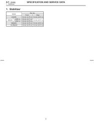
1. POWER SUPPLY<br />
a. The complete power supply circuit will be drawn and described in a separate file.<br />
2. SWITCHING CIRCUIT<br />
a. RLY2 and RLY1 are switched together on one footswitch circuit (“Channel”).<br />
b. RLY3 and RLY4 are switched together on another footswitch circuit (“Effects”).<br />
3. SIGNAL I/O<br />
a. J3 is the input jack. Input impedance >1M.<br />
b. J2 is the low Z Effects Send.<br />
c. J1 is the parallel Effects Return.<br />
d. J4 is the Balanced Output
Questions/Comments:<br />
<strong>Ken</strong> <strong>Gilbert</strong><br />
f. Positive signal excursion of V14’s plate is limited by the action of the relatively low value of Rp,<br />
creating clipping as the plate attempts to soar above the supply rail. This limit of positive excursion<br />
also lessens the effects of grid blocking in the following stage, V10A.<br />
g. R40 is tied to a negative supply rail, and serves to increase the maximum effective negative excursion<br />
of V10A’s grid, delaying pinch off of the plate current. Gain, especially in the HF region, is<br />
maintained by the bypass action of C14.<br />
h. C19-C22, and R46-R51 form a frequency-shaping network that “scoops” mids from the distorted<br />
channel. C19’s dielectric (ceramic, mica, plastic) should be determined empirically since it has a great<br />
effect on the HF response, so try different types here.<br />
i. V8A and V8B form a high gain, low output impedance, inverting amplifier. C8, C9, and R22 are<br />
always “in circuit” and create an additional mid scoop effective on both channels.<br />
j. R20 and R19 set the gain of V8 to be –1 at midband.<br />
k. C7, L1, and R21 set the effective frequency range of the LF and HF shelving filters. C7 determines<br />
the HF break frequency, and the value of R21 affects the Q—or bandwidth—of the LF control.<br />
Sweeping potentiometers R25 and R26 provides for approximately 20 dB boost or cut of LF and HF<br />
respectively. L1 is a scavenged toroidal SMPS inductor, all windings connected in series.<br />
l. The cathode output of V8B also provides low Z drive for an effects loop, accessible through J2.<br />
m. V7A is set up as an inverting, unity gain virtual-earth summing buffer. Overall gain of dry signal is<br />
determined by the ratio of R18 and R15. Likewise, gain of effects signal, injected through J1, is<br />
determined by ratio of R17 and R15. This allows for a virtual-earth at the grid of V7A, and ensures<br />
effective mixing of both signals.<br />
n. V7B is set up similarly, except the “feedback resistance,” R15 in the previous stage, is now variable<br />
resistor R7. This feedback loop allows for an output signal attenuator that exhibits little tonal change<br />
across its range of effectiveness.<br />
o. V1 and V2 are set up as a cross-coupled, or Van Scoyc phase splitter. Bias for the plate loaded,<br />
cathode driven V2 is adjusted via the cathode resistors R5 and R6. Bias for BOTH V1 and V2 is<br />
adjusted via R3 and R4. If a different tube is chosen, these values will need to be redetermined. V1 is<br />
merely a buffer that prevents heavily loading the signal, which would occur if V2’s cathodes were<br />
directly driven.<br />
p. R62, R63 and R60 adjust the frequency and response of the midrange control. They do so by<br />
changing the RC product—the time constant—of V1A’s grid circuit, and thus provide a sweepable<br />
midrange frequency. Degenerative mixing with the full-range signal present at R60 creates a boost or<br />
cut as desired. Together they create a semi-parametric midrange control.<br />
q. J4 presents a medium/low impedance (4k) balanced line output. The shield of J4 should be earthed<br />
at either end, but not both, for best ground loop rejection. Better PSRR and larger output voltage<br />
swings could be achieved with a center tapped inductive load on V2.<br />
r. Output voltage at J4 is sufficient to drive final grids of approximately 50W push-push pull tube power<br />
amplifier.<br />
s. NOTE: all wires should be assumed as CONNECTED except the following crossovers: the junction<br />
to the left of R21 is not a connection, nor is the one near R5 and R6.
RLY4<br />
NORMAL<br />
RLY3<br />
NORMAL<br />
J4<br />
C27<br />
470p<br />
R63<br />
1m 50%<br />
R62<br />
1m 50%<br />
C26<br />
470p<br />
R60<br />
1m 50%<br />
V20<br />
300v<br />
V19<br />
300v<br />
V18<br />
300v<br />
V17<br />
-60v<br />
C1<br />
33n<br />
C2<br />
33n<br />
V1B<br />
6N1P<br />
V1A<br />
6N1P<br />
V2B<br />
6N1P<br />
V2A<br />
6N1P<br />
V3<br />
-60v<br />
R7<br />
1m 50%<br />
C3<br />
200n<br />
V4<br />
300v<br />
C4<br />
1u<br />
C5<br />
1uF<br />
V5<br />
-60v<br />
V6<br />
300v<br />
C6<br />
1u<br />
V7B<br />
12AX7<br />
V7A<br />
12AX7<br />
J1<br />
J2<br />
C7<br />
1uF<br />
RLY1<br />
NORMAL<br />
C8<br />
2.3n<br />
C9<br />
3.8n<br />
R23<br />
100k 50%<br />
L1<br />
370m<br />
C10<br />
1n<br />
R25<br />
1m 50%<br />
R26<br />
1m 50%<br />
V8A<br />
12AX7<br />
V8B<br />
12AX7<br />
C11<br />
25u<br />
V9<br />
300v<br />
C12<br />
5.8u<br />
C13<br />
22n<br />
V10A<br />
12AX7<br />
V10B<br />
12AX7<br />
C14<br />
180n<br />
V11<br />
-60v<br />
V12<br />
300v<br />
V13<br />
300v<br />
C15<br />
10p<br />
C16<br />
47p<br />
C17<br />
680n<br />
C18<br />
100n<br />
R27<br />
1m 50%<br />
V14B<br />
6N1P<br />
V14A<br />
6N1P<br />
R28<br />
1m 50%<br />
R29<br />
100k 50%<br />
C19<br />
100p<br />
C20<br />
3.7n<br />
C21<br />
110n<br />
C22<br />
47n<br />
RLY2<br />
NORMAL<br />
C23<br />
1uF<br />
V15<br />
300v<br />
J3<br />
C24<br />
1uF<br />
C25<br />
35u<br />
V16B<br />
6N1P<br />
V16A<br />
6N1P<br />
R61<br />
650k<br />
R1<br />
33k<br />
R2<br />
33k<br />
R3<br />
10k<br />
R4<br />
10k<br />
R5<br />
680r<br />
R6<br />
680r<br />
R8<br />
100k<br />
R9<br />
56k<br />
R10<br />
1m<br />
R11<br />
10k<br />
R12<br />
100k<br />
R13<br />
56k<br />
R14<br />
1m<br />
R15<br />
47k<br />
R16<br />
100k<br />
R17<br />
47k<br />
R18<br />
47k<br />
R19<br />
470k<br />
R20<br />
470k<br />
R21<br />
56k<br />
R22<br />
56k<br />
R24<br />
100k<br />
R31<br />
58k<br />
R32<br />
58k<br />
R33<br />
58k<br />
R34<br />
58k<br />
R35<br />
100k<br />
R36<br />
33k<br />
R37<br />
1k<br />
R38<br />
1.5m<br />
R39<br />
100k<br />
R40<br />
56k<br />
R41<br />
47k<br />
R42<br />
100k<br />
R43<br />
10k<br />
R44<br />
22k<br />
R45<br />
100k<br />
R46<br />
246r<br />
R47<br />
10k<br />
R48<br />
68k<br />
R49<br />
68k<br />
R50<br />
68k<br />
R51<br />
68k<br />
R52<br />
10k<br />
R53<br />
10k<br />
R54<br />
10k<br />
R55<br />
1m<br />
R56<br />
1m<br />
R57<br />
100k<br />
R58<br />
500r<br />
R59<br />
10k