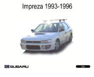
2004 impreza service manual quick reference index ... - Ken Gilbert
2004 impreza service manual quick reference index ... - Ken Gilbert
2004 impreza service manual quick reference index ... - Ken Gilbert

You also want an ePaper? Increase the reach of your titles
YUMPU automatically turns print PDFs into web optimized ePapers that Google loves.
<strong>2004</strong> IMPREZA SERVICE MANUAL QUICK REFERENCE INDEX<br />
CHASSIS SECTION<br />
This <strong>service</strong> <strong>manual</strong> has been prepared<br />
to provide SUBARU <strong>service</strong> personnel<br />
with the necessary information and data<br />
for the correct maintenance and repair<br />
of SUBARU vehicles.<br />
This <strong>manual</strong> includes the procedures<br />
for maintenance, disassembling, reassembling,<br />
inspection and adjustment of<br />
components and diagnostics for guidance<br />
of experienced mechanics.<br />
Please peruse and utilize this <strong>manual</strong><br />
fully to ensure complete repair work for<br />
satisfying our customers by keeping<br />
their vehicle in optimum condition.<br />
When replacement of parts during<br />
repair work is needed, be sure to use<br />
SUBARU genuine parts.<br />
All information, illustration and specifications<br />
contained in this <strong>manual</strong> are<br />
based on the latest product information<br />
available at the time of publication<br />
approval.<br />
FRONT SUSPENSION FS<br />
REAR SUSPENSION RS<br />
WHEEL AND TIRE SYSTEM WT<br />
DIFFERENTIALS DI<br />
TRANSFER CASE TC<br />
DRIVE SHAFT SYSTEM DS<br />
ABS ABS<br />
ABS (DIAGNOSTICS) ABS(diag)<br />
BRAKE BR<br />
PARKING BRAKE PB<br />
POWER ASSISTED SYSTEM<br />
(POWER STEERING)<br />
FUJI HEAVY INDUSTRIES LTD. G1870GE5<br />
PS
REAR SUSPENSION<br />
RS<br />
Page<br />
1. General Description ....................................................................................2<br />
2. Wheel Alignment .......................................................................................10<br />
3. Rear Stabilizer...........................................................................................11<br />
4. Rear Trailing Link ......................................................................................12<br />
5. Rear Strut..................................................................................................16<br />
6. Lateral link.................................................................................................17<br />
7. Rear Crossmember...................................................................................21<br />
8. General Diagnostic Table..........................................................................22
REAR SUSPENSION<br />
1. General Description<br />
A: SPECIFICATIONS<br />
*1 TS, GX: None<br />
RS: 10 mm (0.39 in)<br />
*2 WRX: 20 mm (0.79 in)<br />
STi: 19 mm (0.75 in)<br />
NOTE:<br />
• Front and rear toe-ins and front camber can be<br />
adjusted. If toe-in or camber tolerance exceeds<br />
specifications, adjust toe-in and camber.<br />
• The other items indicated in the specification table<br />
cannot be adjusted. If the other items exceeds<br />
specifications, check suspension parts and connections<br />
for deformities, and replace with new ones<br />
as required.<br />
General Description<br />
Model<br />
Sedan<br />
Non-turbo Turbo<br />
Wagon<br />
Non-turbo Turbo<br />
OUTBACK<br />
Camber (tolerance: ±0°45′) −1°25′ −1°30′ −1°15′ −1°20′ −1°10′<br />
Toe-in mm (in) 0±3 (0±0.12) Each toe angle: ±0°09′<br />
Thrust angle (tolerance: ±0°30′)<br />
Wheel arch height<br />
0°<br />
[tolerance: +12 −24 mm<br />
( +0.47 −0.94 in)]<br />
mm (in) 381 (15.0) 376 (14.80) 381 (15.0) 376 (14.80) 386 (15.20)<br />
Diameter of stabilizer mm (in) *1 *2 — 17 (0.67) —<br />
B<br />
(1)<br />
A<br />
FS-00001<br />
(1) Front<br />
A − B = Positive: Toe-in, Negative: Toe-out<br />
α = Each toe angle<br />
RS-2
B: COMPONENT<br />
1. REAR SUSPENSION<br />
• AWD MODEL<br />
(22)<br />
(22)<br />
T1<br />
(20)<br />
T4<br />
(21)<br />
(23)<br />
(25)<br />
(24)<br />
(27)<br />
(26)<br />
T11<br />
T5<br />
(28)<br />
T7<br />
General Description<br />
(16)<br />
(19)<br />
(22)<br />
T7<br />
(22)<br />
T7<br />
(17)<br />
(18)<br />
(22)<br />
T8<br />
(12)<br />
(22)<br />
T10<br />
RS-3<br />
T5<br />
(11)<br />
(15)<br />
(5)<br />
(9)<br />
(14)<br />
(1)<br />
T3<br />
(22)<br />
T3<br />
(22)<br />
T6<br />
(22)<br />
(13)<br />
(6)<br />
T9<br />
(8)<br />
(10)<br />
(9)<br />
(2)<br />
(9)<br />
T2<br />
(31)<br />
(22)<br />
REAR SUSPENSION<br />
(4)<br />
(7)<br />
(10)<br />
(3)<br />
T3<br />
(29)<br />
(10)<br />
T2<br />
T2<br />
(30)<br />
RS-00139
REAR SUSPENSION<br />
General Description<br />
(1) Stabilizer (15) Trailing link front bushing (30) Stabilizer link (STi model)<br />
(2) Stabilizer bracket (16) Trailing link bracket (31) Rear lateral link (STi model)<br />
(3) Stabilizer bushing (17) Cap (Protection)<br />
(4) Clamp (18) Washer Tightening torque: N·m (kgf-m, ft-lb)<br />
(5) Floating bushing (19) Rear crossmember T1: 20 (2.0, 14.5)<br />
(6) Stopper (20) Strut mount cap T2: 25 (2.5, 18.1)<br />
(7) Stabilizer link (except STi model) (21) Strut mount T3: 45 (4.6, 33.2)<br />
(8) Rear lateral link (with stabilizer,<br />
except STi model)<br />
(22) Self-locking nut T4: 55 (5.6, 41)<br />
(23) Dust cover T5: 70 (7.1, 52)<br />
(9) Bushing (C) (24) Coil spring T6: 90 (9.2, 66)<br />
(10) Bushing (A) (25) Helper T7: 100 (10.2, 74)<br />
(11) Front lateral link (26) Lower rubber seat T8: 115 (11.7, 85)<br />
(12) Bushing (B) (27) Damper strut T9: 130 (13.3, 96)<br />
(13) Trailing link rear bushing (28) Rear differential member rear T10: 140 (14.3, 103)<br />
(14) Trailing link (29) Rear lateral link (without stabilizer) T11: 200 (20.0, 145 )<br />
RS-4
• FWD model<br />
T1<br />
(15)<br />
(7)<br />
(16)<br />
(17)<br />
(18)<br />
(19)<br />
(20)<br />
(21)<br />
(7)<br />
T8<br />
T2<br />
General Description<br />
(9)<br />
(13)<br />
T4<br />
RS-5<br />
REAR SUSPENSION<br />
RS-00099<br />
(1) Adjusting bolt (12) Trailing link front bushing Tightening torque: N·m (kgf-m, ft-lb)<br />
(2) Adjusting wheel (13) Trailing link bracket T1: 20 (2.0, 14.5)<br />
(3) Rear lateral link (14) Rear crossmember T2: 55 (5.6, 41)<br />
(4) Bushing (D) (15) Strut mount cap T3: 90 (9.2, 66)<br />
(5) Bushing (A) (16) Strut mount T4: 100 (10.2, 74)<br />
(6) Front lateral link (17) Dust cover T5: 115 (11.7, 85)<br />
(7) Self-locking nut (18) Coil spring T6: 130 (13.3, 96)<br />
(8) Washer (19) Helper T7: 135 (13.8, 100)<br />
(9) Cap (Protection) (20) Lower rubber seat T8: 220 (22.4, 162)<br />
(10) Trailing link rear bushing (21) Damper strut<br />
(11) Trailing link<br />
(14)<br />
(7)<br />
(8)<br />
T7<br />
T5<br />
(5)<br />
(7)<br />
T7<br />
(6)<br />
(7)<br />
(5)<br />
T6<br />
(11)<br />
(12)<br />
(4)<br />
(7)<br />
(2)<br />
(10)<br />
T3<br />
(1)<br />
(3)<br />
(5)
REAR SUSPENSION<br />
C: CAUTION<br />
• Wear working clothing, including a cap, protective<br />
goggles, and protective shoes during operation.<br />
• Before disposing shock absorbers, be sure to<br />
bleed gas completely. Also, do not throw away in<br />
fire.<br />
• Before removal, installation or disassembly, be<br />
sure to clarify the failure. Avoid unnecessary removal,<br />
installation, disassembly, and replacement.<br />
• Use SUBARU genuine grease etc. or the equivalent.<br />
Do not mix grease etc. with that of another<br />
grade or from other manufacturers.<br />
• Be sure to tighten fasteners including bolts and<br />
nuts to the specified torque.<br />
• Place shop jacks or rigid racks at the specified<br />
points.<br />
• Before securing a part on a vise, place cushioning<br />
material such as wood blocks, aluminum plate,<br />
or shop cloth between the part and the vise.<br />
General Description<br />
RS-6
D: PREPARATION TOOL<br />
1. SPECIAL TOOLS<br />
(1)<br />
General Description<br />
RS-7<br />
REAR SUSPENSION<br />
ILLUSTRATION TOOL NUMBER DESCRIPTION REMARKS<br />
927380002 ADAPTER Used as an adapter for camber & caster gauge<br />
when measuring camber and caster.<br />
(1) 28199AC000 PLATE<br />
(2) 28199AC010 BOLT<br />
(2)<br />
ST-927380002<br />
ST-927720000<br />
ST-927730000<br />
ST28099PA090<br />
927720000 INSTALLER &<br />
REMOVER<br />
927730000 INSTALLER &<br />
REMOVER<br />
28099PA090 OIL SEAL PROTEC-<br />
TOR<br />
Used for replacing front bushing.<br />
Used for replacing rear bushing.<br />
• Used for installing rear drive shaft to rear differential.<br />
• For protecting oil seal.
REAR SUSPENSION<br />
General Description<br />
ILLUSTRATION TOOL NUMBER DESCRIPTION REMARKS<br />
28099PA100 REMOVER Used for removing DOJ.<br />
ST28099PA100<br />
ST-927710000<br />
ST-927700000<br />
ST-927690000<br />
927710000 INSTALLER &<br />
REMOVER<br />
927700000 INSTALLER &<br />
REMOVER<br />
927690000 INSTALLER &<br />
REMOVER<br />
RS-8<br />
Used for replacing lateral link bushing.<br />
Used for replacing lateral link bushing.<br />
Used for replacing lateral link bushing.
2. GENERAL PURPOSE TOOLS<br />
General Description<br />
TOOL NAME REMARKS<br />
Alignment gauge Used for wheel alignment measurement.<br />
Turning radius gauge Used for wheel alignment measurement.<br />
Toe-in gauge Used for toe-in measurement.<br />
Transmission jack Used for suspension assembly/disassembly.<br />
Bearing puller Used for removing bushings.<br />
Coil spring compressor Used for strut assembly/disassembly.<br />
RS-9<br />
REAR SUSPENSION
REAR SUSPENSION<br />
2. Wheel Alignment<br />
A: INSPECTION<br />
NOTE:<br />
Front and rear wheel alignment must be simultaneously<br />
measured and/or adjusted. Follow the procedure<br />
in “FS” section “Wheel Alignment” for<br />
measurement and/or adjustment of wheel alignment.<br />
<br />
Wheel Alignment<br />
RS-10
3. Rear Stabilizer<br />
A: REMOVAL<br />
1) Lift-up the vehicle.<br />
2) Remove the stabilizer link.<br />
• Except STi MODEL<br />
• STi MODEL<br />
RS-00100<br />
RS-00140<br />
3) Remove the bolt and nut which secure the stabilizer<br />
to stabilizer bracket.<br />
RS-00141<br />
Rear Stabilizer<br />
RS-11<br />
REAR SUSPENSION<br />
B: INSTALLATION<br />
1) Install in the reverse order of removal.<br />
NOTE:<br />
• Install the stabilizer bushing while aligning it with<br />
paint mark on stabilizer.<br />
• Ensure the stabilizer bushing and stabilizer have<br />
the same identification colors when installing.<br />
(1) Mark painted on stabilizer<br />
(2) Bushing identification color<br />
2) Always tighten the stabilizer bushing location<br />
when tires are in full contact with the ground and<br />
the vehicle is curb weight.<br />
Tightening torque:<br />
Stabilizer link to rear lateral link<br />
45 N·m (4.6 kgf-m, 33.2 ft-lb)<br />
Stabilizer to stabilizer bracket<br />
25 N·m (2.5 kgf-m, 18.1 ft-lb)<br />
C: INSPECTION<br />
1) Check the bushing for cracks, fatigue or damage.<br />
2) Check the stabilizer links for deformities, cracks,<br />
or damage, and bushing for protrusions from the<br />
hole of stabilizer link.<br />
(2)<br />
(1)<br />
RS-00142
REAR SUSPENSION<br />
4. Rear Trailing Link<br />
A: REMOVAL<br />
1) Loosen the rear wheel nuts.<br />
2) Lift-up the vehicle, and then remove the rear<br />
wheels.<br />
3) Remove both the rear parking brake clamp and<br />
ABS wheel speed sensor harness.<br />
4) Remove the bolt which secures the trailing link to<br />
trailing link bracket.<br />
(1) Trailing link<br />
5) Remove the bolt which secures the trailing link to<br />
rear housing.<br />
B: INSTALLATION<br />
1) Install in the reverse order of removal.<br />
2) Always tighten the bushing location when tires<br />
are in full contact with the ground and the vehicle is<br />
at curb weight condition.<br />
NOTE:<br />
Check the wheel alignment and adjust if necessary.<br />
Rear Trailing Link<br />
RS-00013<br />
RS-12<br />
C: DISASSEMBLY<br />
1. FRONT BUSHING<br />
Using the ST, press the front bushing out of place.<br />
ST 927720000 INSTALLER & REMOVER<br />
SET<br />
(2)<br />
(1)<br />
(1) Press<br />
(2) Trailing link<br />
ST<br />
RS-00014
2. REAR BUSHING<br />
Using the ST, press the rear bushing out of place.<br />
ST 927730000 INSTALLER & REMOVER<br />
SET<br />
(1) Press<br />
(2) Housing<br />
Rear Trailing Link<br />
RS-00015<br />
RS-13<br />
D: ASSEMBLY<br />
REAR SUSPENSION<br />
1. FRONT BUSHING<br />
Using the ST, press the bushing into trailing link.<br />
ST 927720000 INSTALLER & REMOVER<br />
SET<br />
CAUTION:<br />
Turn the ST plunger upside down and press it<br />
until the plunger end surface contacts the trailing<br />
link end surface.<br />
(2)<br />
(3)<br />
(1) Press<br />
(2) Front bushing<br />
(3) Trailing link<br />
CAUTION:<br />
Install the front bushing in the proper direction,<br />
as shown in the figure.<br />
(2)<br />
(1) Front<br />
(2) ±5°<br />
(1)<br />
(1)<br />
ST<br />
RS-00017<br />
RS-00110
REAR SUSPENSION<br />
2. REAR BUSHING<br />
1) Using the ST, press the bushing into trailing link.<br />
ST 927730000 INSTALLER & REMOVER<br />
SET<br />
NOTE:<br />
If it is difficult to press the bushing into trailing link,<br />
apply water-diluted TIRE LUBE to the inner surface<br />
of ST as a lubricant.<br />
Specified lubricant:<br />
TIRE LUBE: water = 1 : 3<br />
(1) Press<br />
(1)<br />
ST<br />
Rear Trailing Link<br />
RS-00018<br />
RS-14<br />
2) Press the ST plunger until the bushing flange<br />
protrudes beyond trailing link.<br />
ST 927730000 INSTALLER & REMOVER<br />
SET<br />
(1) Plunger<br />
(2) Flange<br />
RS-00019
3) Turn the trailing link upside down. Press the ST<br />
plunger in the opposite direction that outlines in the<br />
former procedure until bushing is correctly positioned<br />
in trailing link.<br />
ST 927730000 INSTALLER & REMOVER<br />
SET<br />
(1) Press<br />
(2) Plunger<br />
Rear Trailing Link<br />
RS-00020<br />
E: INSPECTION<br />
Check the trailing links for bends, corrosion or damage.<br />
RS-15<br />
REAR SUSPENSION
REAR SUSPENSION<br />
5. Rear Strut<br />
A: REMOVAL<br />
1) Remove the rear seat cushion and backrest.<br />
(Sedan model)<br />
2) Remove the strut cap of quarter trim. (Wagon<br />
model)<br />
3) Loosen the rear wheel nuts.<br />
4) Lift-up the vehicle, and remove rear wheels.<br />
5) Remove the brake hose clip, and then remove<br />
the brake hose from rear strut.<br />
(1) Brake hose clip<br />
(2) Brake hose<br />
RS-00021<br />
6) Remove the bolts which secure the rear strut to<br />
housing.<br />
RS-00022<br />
7) Remove the nuts securing strut mount to body.<br />
Rear Strut<br />
RS-16<br />
B: INSTALLATION<br />
1) Secure the strut mount to vehicle body using a<br />
new self-locking nut.<br />
Tightening torque:<br />
20 N·m (2.0 kgf-m, 14.5 ft-lb)<br />
2) Secure the rear strut to housing using a new<br />
self-locking nut.<br />
Tightening torque:<br />
200 N·m (20.0 kgf-m, 145 ft-lb)<br />
3) Install the brake hose to lower side of strut, then<br />
insert the brake hose clip.<br />
CAUTION:<br />
• Check the hose clip is positioned properly.<br />
• Check the brake hose for twisting, or excessive<br />
tension.<br />
• Do not subject the ABS wheel speed sensor<br />
harness to excessive tension.<br />
4) Lower the vehicle and tighten wheel nut.<br />
Tightening torque:<br />
90 N·m (9.2 kgf-m, 66 ft-lb)<br />
5) Install the rear seat backrest and rear seat cushion.<br />
(Sedan model)<br />
6) Install the strut cap to rear quarter trim. (Wagon<br />
model)<br />
NOTE:<br />
Check the wheel alignment and adjust if necessary.<br />
C: DISASSEMBLY<br />
For disassembly of rear strut, refer to procedures<br />
outlined under front strut as a guide. <br />
D: ASSEMBLY<br />
Refer to Front Strut as a guide for assembly procedures.<br />
<br />
E: INSPECTION<br />
Refer to Front Strut as a guide for inspection procedures.<br />
<br />
F: DISPOSAL<br />
Refer to Front Strut as a guide for disposal procedures.<br />
6. Lateral link<br />
A: REMOVAL<br />
1) Loosen the wheel nuts. Lift-up the vehicle and<br />
remove wheel.<br />
2) Remove the stabilizers.<br />
3) Remove the ABS wheel speed sensor harness<br />
from trailing link.<br />
4) Remove the bolt securing trailing link to rear<br />
housing.<br />
(1) Rear housing<br />
(2) Trailing link<br />
5) Remove the bolts which secure the lateral link<br />
assembly to rear housing.<br />
6) Remove the DOJ from rear differential using ST.<br />
(T-type)<br />
ST 28099PA100 DRIVE SHAFT REMOVER<br />
NOTE:<br />
The side spline shaft circlip comes out together<br />
with the shaft.<br />
(1) Bolt<br />
(2) DOJ<br />
RS-00024<br />
RS-00025<br />
CAUTION:<br />
Be careful not to damage the side bearing retainer.<br />
Always use bolt shown in the figure, as<br />
supporting point for ST during removal.<br />
Lateral link<br />
RS-17<br />
REAR SUSPENSION<br />
7) Remove the DOJ from rear differential using tire<br />
lever. (VA-type)<br />
NOTE:<br />
The side spline shaft circlip comes out together<br />
with the shaft.<br />
(1) Tire lever<br />
CAUTION:<br />
When removing the DOJ from rear differential,<br />
fit tire lever to the bolt as shown in the figure so<br />
as not to damage axle shaft holder.<br />
(1) Axle shaft holder<br />
RS-00026<br />
RS-00027<br />
8) Scribe an alignment mark on the rear lateral link<br />
adjusting bolt and crossmember.<br />
9) Remove the bolts securing front and rear lateral<br />
links to crossmember, detach lateral links.<br />
CAUTION:<br />
To loosen the adjusting bolt, always loosen the<br />
nut while holding head of adjusting bolt.
REAR SUSPENSION<br />
B: INSTALLATION<br />
Install in the reverse order of removal. Observe the<br />
following instructions.<br />
• Installation of DOJ to differential: <br />
CAUTION:<br />
• Replace the self-locking nut and DOJ circlip<br />
with new ones.<br />
• Always use the special tool not to allow the<br />
DOJ splines to damage the side oil seal.<br />
ST 28099PA090 OIL SEAL PROTECTOR<br />
• Always tighten the bushing location when<br />
tires are in full contact with the ground and vehicle<br />
is curb weight.<br />
• Secure the bolt head and tighten the nut<br />
when installing the adjusting bolt.<br />
NOTE:<br />
Check the wheel alignment and adjust if necessary.<br />
C: DISASSEMBLY<br />
1) Using the following table as a guide, verify the<br />
type of bushings.<br />
2) Select the ST according to type of bushings<br />
used.<br />
Bushing ST: INSTALLER & REMOVER SET<br />
Bushing A 927700000<br />
Bushing B 927690000<br />
Bushing C 927700000<br />
Bushing D 927710000<br />
(2)<br />
(4)<br />
(3)<br />
(1)<br />
(1)<br />
(5)<br />
(1) Bushing A<br />
(2) FWD: Bushing A, AWD: Bushing B<br />
(3) FWD: Bushing D, AWD: Bushing C<br />
(4) Front<br />
(5) Outside of body<br />
RS-00004<br />
Lateral link<br />
RS-18<br />
3) Using the ST, press the bushing out of place.<br />
(1) Press<br />
(2) Lateral link<br />
RS-00029<br />
D: ASSEMBLY<br />
1) Use the same ST that was used during disassembly.<br />
2) If it is difficult to press the bushing into trailing<br />
link, apply water-diluted TIRE LUBE to the inner<br />
surface of ST as a lubricant.<br />
Specified lubricant:<br />
TIRE LUBE: water = 1 : 3
Lateral link<br />
RS-19<br />
REAR SUSPENSION<br />
3) Using the ST, press the bushing into place. 4) Press the ST plunger until bushing flange protrudes<br />
beyond lateral link.<br />
(1) Press<br />
(2) Bushing<br />
(3) Lateral link<br />
RS-00030<br />
(1) Press<br />
(2) Plunger<br />
(3) Lateral link<br />
(4) Flange<br />
RS-00031
REAR SUSPENSION<br />
5) Turn the lateral link upside down. Press the ST<br />
plunger in opposite direction that outlined in the<br />
former procedure until bushing is correctly positioned<br />
in trailing link.<br />
(1) Press<br />
(2) Plunger<br />
(3) Lateral link<br />
RS-00032<br />
E: INSPECTION<br />
Visually check the lateral links for damage or<br />
bends.<br />
Lateral link<br />
RS-20
7. Rear Crossmember<br />
A: REMOVAL<br />
1. AWD MODEL<br />
CAUTION:<br />
Do not subject the ABS wheel speed sensor<br />
harness to excessive tension.<br />
1) Separate the front exhaust pipe and rear exhaust<br />
pipe.<br />
2) Remove the rear exhaust pipe and muffler.<br />
3) Remove the rear differential.<br />
T-type<br />
<br />
VA-type<br />
<br />
4) Place the transmission jack under rear crossmember.<br />
5) Remove the bolts securing crossmember to vehicle<br />
body, and then remove the crossmember.<br />
6) Scribe an alignment mark on the rear lateral link<br />
cam bolt and crossmember.<br />
7) Remove the front and rear lateral links by loosening<br />
nuts.<br />
2. FWD MODEL<br />
1) Remove the bolts which secure the lateral link<br />
assembly to rear housing.<br />
2) Remove the rear exhaust pipe and muffler.<br />
3) Remove the heat shield cover.<br />
Rear Crossmember<br />
RS-00033<br />
RS-00034<br />
RS-21<br />
REAR SUSPENSION<br />
4) Remove the bolt securing crossmember to body,<br />
and then remove the crossmember.<br />
B: INSTALLATION<br />
1. AWD MODEL<br />
RS-00105<br />
NOTE:<br />
• Discard the loosened self-locking nut and replace<br />
it with a new one.<br />
• Always secure the bolt head and tighten the nut<br />
when tightening the adjusting bolt.<br />
1) Install in the reverse order of removal.<br />
2) For installation and tightening torque of rear differential;<br />
T-type<br />
<br />
VA-type<br />
<br />
3) Always tighten the rubber bushing when tires are<br />
in full contact with the ground and vehicle is curb<br />
weight.<br />
4) Check the wheel alignment and adjust if necessary.<br />
2. FWD MODEL<br />
NOTE:<br />
• Discard the loosened self-locking nut and replace<br />
it with a new one.<br />
• Always secure the bolt head and tighten the nut<br />
when tightening adjusting bolt.<br />
1) Install in the reverse order of removal.<br />
2) Always tighten the rubber bushing when tires are<br />
in full contact with the ground and vehicle is curb<br />
weight.<br />
3) Check the wheel alignment and adjust if necessary.<br />
C: INSPECTION<br />
Check the removed parts for wear, damage and<br />
cracks, and correct or replace if defective.
REAR SUSPENSION<br />
8. General Diagnostic Table<br />
A: INSPECTION<br />
General Diagnostic Table<br />
1. IMPROPER VEHICLE POSTURE OR IMPROPER WHEEL ARCH HEIGHT<br />
Possible causes Countermeasures<br />
(1) Permanent distortion or breakage of coil spring Replace.<br />
(2) Unsmooth operation of damper strut or shock absorber Replace.<br />
(3) Installation of wrong strut or shock absorber Replace with proper parts.<br />
(4) Installation of wrong coil spring Replace with proper parts.<br />
2. POOR RIDE COMFORT<br />
1) Large rebound shock<br />
2) Rocking of the vehicle continues too long after running over bump and/or hump<br />
3) Large shock in bumping<br />
Possible causes Countermeasures<br />
(1) Breakage of coil spring Replace.<br />
(2) Overinflating pressure of tire Adjust.<br />
(3) Improper wheel arch height Adjust or replace the coil springs with new ones.<br />
(4) Fault in operation of damper strut or shock absorber Replace.<br />
(5) Damage or deformation of strut mount or shock absorber mount Replace.<br />
(6) Unsuitability of maximum or minimum length of damper strut or shock<br />
absorber<br />
Replace with proper parts.<br />
(7) Deformation or loss of bushing Replace.<br />
(8) Deformation or damage of helper in strut assembly or shock absorber Replace.<br />
(9) Oil leakage of damper strut or shock absorber Replace.<br />
3. NOISE<br />
Possible causes Countermeasures<br />
(1) Wear or damage of damper strut or shock absorber component parts Replace.<br />
(2) Loosening of suspension link installing bolt Retighten to the specified torque.<br />
(3) Deformation or loss of bushing Replace.<br />
(4) Unsuitability of maximum or minimum length of damper strut or shock<br />
absorber<br />
Replace with proper parts.<br />
(5) Breakage of coil spring Replace.<br />
(6) Wear or damage of ball joint Replace.<br />
(7) Deformation of stabilizer clamp Replace.<br />
RS-22