Transmission and Differential.pdf - Ken Gilbert
Transmission and Differential.pdf - Ken Gilbert
Transmission and Differential.pdf - Ken Gilbert

Create successful ePaper yourself
Turn your PDF publications into a flip-book with our unique Google optimized e-Paper software.
3-1 [S100] SPECIFICATIONS AND SERVICE DATA<br />
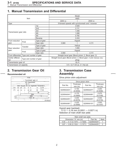
1. Manual <strong>Transmission</strong> <strong>and</strong> <strong>Differential</strong><br />
1. Manual <strong>Transmission</strong> <strong>and</strong> <strong>Differential</strong><br />
Model<br />
Item<br />
AWD<br />
2200 cc 2500 cc<br />
Type 5-forward speeds with synchromesh <strong>and</strong> 1-reverse<br />
1st 3.545<br />
2nd 2.111<br />
<strong>Transmission</strong> gear ratio<br />
3rd<br />
4th<br />
1.448<br />
1.088<br />
5th 0.780<br />
Reverse 3.333<br />
Front reduction<br />
gear<br />
Rear reduction<br />
gear<br />
Final<br />
Transfer<br />
Final<br />
Type of gear Hypoid<br />
Gear ratio 3.900 4.111<br />
Type of gear Helical<br />
Gear ratio 1.000<br />
Type of gear Hypoid<br />
Gear ratio 3.900 4.111<br />
Front differential Type <strong>and</strong> number of gear Straight bevel gear (Bevel pinion: 2, Bevel gear: 2)<br />
Center differential<br />
Type <strong>and</strong> number of gear<br />
Straight bevel gear (Bevel pinion: 2, Bevel gear: 2 <strong>and</strong> viscous coupling)<br />
<strong>Transmission</strong> gear oil GL-5<br />
<strong>Transmission</strong> oil capacity 3.5 (3.7 US qt, 3.1 Imp qt)<br />
2. <strong>Transmission</strong> Gear Oil<br />
Recommended oil<br />
B1H0024<br />
2<br />
3. <strong>Transmission</strong> Case<br />
Assembly<br />
Drive pinion shim adjustment<br />
Part No.<br />
32295AA031<br />
32295AA041<br />
32295AA051<br />
32295AA061<br />
Drive pinion shim<br />
Thickness<br />
mm (in)<br />
0.150<br />
(0.0059)<br />
0.175<br />
(0.0069)<br />
0.200<br />
(0.0079)<br />
0.225<br />
(0.0089)<br />
Part No.<br />
32295AA071<br />
32295AA081<br />
32295AA091<br />
32295AA101<br />
Hypoid gear backlash<br />
0.13 — 0.18 mm (0.0051 — 0.0071 in)<br />
Selection of main shaft rear plate<br />
Thickness<br />
mm (in)<br />
0.250<br />
(0.0098)<br />
0.275<br />
(0.0108)<br />
0.300<br />
(0.0118)<br />
0.500<br />
(0.0197)<br />
Main shaft rear plate<br />
Dimension “A” mm (in) Part No. Mark<br />
4.00 — 4.13 (0.1575 — 0.1626) 32294AA041 1<br />
3.87 — 3.99 (0.1524 — 0.1571) 32294AA051 2
4. Drive Pinion Assembly<br />
Preload adjustment of thrust bearing<br />
Starting torque<br />
0.3 — 0.8 N·m<br />
(0.03 — 0.08 kg-m, 0.2 — 0.6 ft-lb)<br />
Adjusting washer No. 1<br />
Part No. Thickness mm (in)<br />
803025051 3.925 (0.1545)<br />
803025052 3.950 (0.1555)<br />
803025053 3.975 (0.1565)<br />
803025054 4.000 (0.1575)<br />
803025055 4.025 (0.1585)<br />
803025056 4.050 (0.1594)<br />
803025057 4.075 (0.1604)<br />
Adjusting washer No. 2<br />
Part No. Thickness mm (in)<br />
803025059 3.850 (0.1516)<br />
803025054 4.000 (0.1575)<br />
803025058 4.150 (0.1634)<br />
SPECIFICATIONS AND SERVICE DATA<br />
3<br />
5. Reverse Idler Gear<br />
Adjustment of reverse idler gear position<br />
Reverse idler gear to transmission case (LH) wall<br />
clearance<br />
6.0 — 7.5 mm (0.236 — 0.295 in)<br />
Part No.<br />
Reverse shifter lever<br />
Mark Remarks<br />
32820AA070 7 Further from case wall<br />
32820AA080 8 St<strong>and</strong>ard<br />
32820AA090 9 Closer to the case wall<br />
After installing a suitable reverse shifter lever,<br />
adjust reverse idler gear to transmission case wall<br />
clearance to within 0 to 0.5 mm (0 to 0.020 in)<br />
using washers.<br />
Part No.<br />
Washer (20.5 × 26 × t)<br />
Thickness<br />
mm (in)<br />
[S500] 3-1<br />
5. Reverse Idler Gear<br />
Part No.<br />
Thickness<br />
mm (in)<br />
803020151 0.4 (0.016) 803020154 1.9 (0.075)<br />
803020152 1.1 (0.043) 803020155 2.3 (0.091)<br />
803020153 1.5 (0.059)
3-1 [S600] SPECIFICATIONS AND SERVICE DATA<br />
6. Shifter Fork <strong>and</strong> Rod<br />
6. Shifter Fork <strong>and</strong> Rod<br />
Select suitable shifter forks so that both coupling<br />
sleeve <strong>and</strong> reverse driven gear are positioned in<br />
the center of their synchromesh mechanisms.<br />
Part No.<br />
1st-2nd shifter fork<br />
Mark Remarks<br />
32804AA060 1<br />
Approach to 1st gear by 0.2<br />
mm (0.008 in)<br />
32804AA070 No mark St<strong>and</strong>ard<br />
32804AA080 3<br />
Approach to 2nd gear by<br />
0.2 mm (0.008 in)<br />
Part No.<br />
3rd-4th shifter fork<br />
Mark Remarks<br />
32810AA061 1<br />
Approach to 4th gear by 0.2<br />
mm (0.008 in)<br />
32810AA071 No mark St<strong>and</strong>ard<br />
32810AA101 3<br />
Approach to 3rd gear by 0.2<br />
mm (0.008 in)<br />
Part No.<br />
5th shifter fork<br />
Mark Remarks<br />
32812AA201 7<br />
Approach to 5th gear by 0.2<br />
mm (0.008 in)<br />
32812AA211 No mark St<strong>and</strong>ard<br />
32812AA221 9<br />
Become distant from 5th<br />
gear by 0.2 mm (0.008 in)<br />
Rod end clearance<br />
A: 1st-2nd — 3rd-4th<br />
0.4 — 1.4 mm (0.016 — 0.055 in)<br />
B: 3rd-4th — 5th<br />
0.5 — 1.3 mm (0.020 — 0.051 in)<br />
4<br />
7. Transfer Case<br />
Neutral position adjustment<br />
Part No.<br />
Adjustment shim<br />
Thickness mm (in)<br />
32190AA000 0.15 (0.0059)<br />
32190AA010 0.30 (0.0118)<br />
Part No.<br />
Reverse accent shaft<br />
Mark Remarks<br />
32188AA090 X<br />
Neutral position is closer to<br />
1st gear.<br />
32188AA100 Y St<strong>and</strong>ard<br />
32188AA110 Z<br />
Neutral position is closer to<br />
reverse gear.<br />
Reverse check plate adjustment<br />
Reverse check plate<br />
Part No. Mark Angle θ Remarks<br />
Arm stops<br />
32189AA000 0 28° closer to 5th<br />
gear.<br />
Arm stops<br />
32189AA010 1 31° closer to 5th<br />
gear.<br />
33189AA020 2 34°<br />
Arm stops in<br />
the center.<br />
Arm stops<br />
32189AA030 3 37° closer to<br />
reverse gear.<br />
Arm stops<br />
32189AA040 4 40° closer to<br />
reverse gear.
8. Extension Assembly<br />
Thrust washer (52 × 61 × t) to ball bearing side<br />
clearance<br />
0.05 — 0.30 mm (0.0020 — 0.0118 in)<br />
Thrust washer (52 × 61 × t)<br />
Part No. Thickness mm (in)<br />
803052021 0.50 (0.0197)<br />
803052022 0.75 (0.0295)<br />
803052023 1.00 (0.0394)<br />
Thrust washer to center differential side clearance<br />
0.15 — 0.35 mm (0.0059 — 0.0138 in)<br />
Part No.<br />
Thrust washer<br />
Thickness mm (in)<br />
803036050 0.9 (0.035)<br />
803036054 1.0 (0.039)<br />
803036051 1.1 (0.043)<br />
803036055 1.2 (0.047)<br />
803036052 1.3 (0.051)<br />
803036056 1.4 (0.055)<br />
803036053 1.5 (0.059)<br />
803036057 1.6 (0.063)<br />
803036058 1.7 (0.067)<br />
SPECIFICATIONS AND SERVICE DATA<br />
5<br />
9. Front <strong>Differential</strong><br />
Bevel gear to pinion backlash<br />
0.13 — 0.18 mm (0.0051 — 0.0071 in)<br />
Part No.<br />
803038021<br />
803038022<br />
Washer (38.1 × 50 × t)<br />
Thickness<br />
mm (in)<br />
0.925 —<br />
0.950<br />
(0.0364 —<br />
0.0374)<br />
0.975 —<br />
1.000<br />
(0.0384 —<br />
0.0394)<br />
Part No.<br />
803038023<br />
Thickness<br />
mm (in)<br />
1.025 —<br />
1.050<br />
(0.0404 —<br />
0.0413)<br />
— —<br />
Pinion shaft to axle drive shaft clearance<br />
0 — 0.25 mm (0 — 0.0098 in)<br />
Part No.<br />
Snap ring (Outer-28)<br />
Thickness<br />
mm (in)<br />
Part No.<br />
[S900] 3-1<br />
9. Front <strong>Differential</strong><br />
Thickness<br />
mm (in)<br />
805028011 1.05 (0.0413) 805028012 1.20 (0.0472)
3-1 [C100] COMPONENT PARTS<br />
1. <strong>Transmission</strong> Case<br />
1. <strong>Transmission</strong> Case<br />
(1) <strong>Transmission</strong> case ASSY<br />
(2) Gasket<br />
(3) Drain plug<br />
(4) Snap ring (Outer)<br />
(5) Speedometer driven gear<br />
(6) Washer<br />
(7) Speedometer shaft<br />
(8) Snap ring (Outer)<br />
(9) Oil seal<br />
(10) Oil level gauge<br />
(11) Pitching stopper bracket<br />
(12) Clamp<br />
6<br />
(13) Clip<br />
B3M1356A<br />
Tightening torque: N·m (kg-m, ft-lb)<br />
T: 44±3 (4.5±0.3, 32.5±2.2)<br />
Size All models Torque<br />
25±2 N·m<br />
8 mm bolt — (2.5±0.2 kg-m,<br />
18.1±1.4 ft-lb)<br />
10 mm bolt<br />
— <br />
— <br />
39±3 N·m<br />
(4.0±0.3 kg-m,<br />
28.9±2.2 ft-lb)
2. Drive Pinion Assembly<br />
A: 2200 cc MODEL<br />
(1) Drive pinion shaft<br />
(2) Roller bearing<br />
(3) Washer<br />
(4) Thrust bearing<br />
(5) Needle bearing<br />
(6) Driven shaft<br />
(7) Key<br />
(8) Woodruff key<br />
(9) Drive pinion collar<br />
(10) Needle bearing<br />
(11) Snap ring (Outer)<br />
(12) Washer<br />
(13) Sub gear<br />
COMPONENT PARTS<br />
(14) 1st driven gear<br />
(15) Baulk ring<br />
(16) 1st-2nd synchronizer hub<br />
(17) Insert key<br />
(18) Reverse driven gear<br />
(19) Baulk ring<br />
(20) 2nd driven gear<br />
(21) 2nd driven gear bush<br />
(22) 3rd-4th driven gear<br />
(23) Driven pinion shim<br />
(24) Roller bearing<br />
(25) 5th driven gear<br />
(26) Lock washer<br />
7<br />
[C2A0] 3-1<br />
2. Drive Pinion Assembly<br />
H3M1778A<br />
(27) Lock nut<br />
(28) Washer<br />
(29) Thrust bearing<br />
(30) <strong>Differential</strong> bevel gear sleeve<br />
(31) Washer<br />
(32) Lock washer<br />
(33) Lock nut<br />
Tightening torque: N·m (kg-m, ft-lb)<br />
T1: 29±3 (3.0±0.3, 21.7±2.2)<br />
T2: 118±8 (12.0±0.8, 86.8±5.8)<br />
T3: 265±10 (27±1, 195±7)
3-1 [C2B0] COMPONENT PARTS<br />
2. Drive Pinion Assembly<br />
B: 2500 cc MODEL<br />
(1) Drive pinion shaft<br />
(2) Roller bearing<br />
(3) Washer<br />
(4) Thrust bearing<br />
(5) Needle bearing<br />
(6) Driven shaft<br />
(7) Key<br />
(8) Woodruff key<br />
(9) Drive pinion collar<br />
(10) Needle bearing<br />
(11) Snap ring (Outer)<br />
(12) Washer<br />
(13) Sub gear<br />
(14) 1st driven gear<br />
(15) Baulk ring<br />
(16) 1st-2nd synchronizer hub<br />
(17) Insert key<br />
(18) Reverse driven gear<br />
(19) Outer baulk ring<br />
(20) Synchro cone<br />
(21) Inner baulk ring<br />
(22) 2nd driven gear<br />
(23) 2nd driven gear bush<br />
(24) 3rd-4th driven gear<br />
(25) Driven pinion shim<br />
(26) Roller bearing<br />
(27) 5th driven gear<br />
(28) Lock washer<br />
8<br />
S3M0423A<br />
(29) Lock nut<br />
(30) Washer<br />
(31) Thrust bearing<br />
(32) <strong>Differential</strong> bevel gear sleeve<br />
(33) Washer<br />
(34) Lock washer<br />
(35) Lock nut<br />
Tightening torque: N·m (kg-m, ft-lb)<br />
T1: 29±3 (3.0±0.3, 21.7±2.2)<br />
T2: 118±8 (12.0±0.8, 86.8±5.8)<br />
T3: 265±10 (27±1, 195±7)
3. Main Shaft Assembly<br />
A: 2200 cc MODEL<br />
(1) Oil seal<br />
(2) Needle bearing<br />
(3) <strong>Transmission</strong> main shaft<br />
(4) Needle bearing<br />
(5) 3rd drive gear<br />
(6) 3rd baulk ring<br />
(7) Coupling sleeve<br />
(8) Synchronizer hub<br />
(9) Shifting insert key<br />
(10) 4th baulk ring<br />
(11) 4th drive gear<br />
(12) 4th needle bearing race<br />
COMPONENT PARTS<br />
(13) Needle bearing<br />
(14) 4th gear thrust washer<br />
(15) Ball bearing<br />
(16) 5th gear thrust washer<br />
(17) 5th needle bearing race<br />
(18) Needle bearing<br />
(19) Main shaft rear plate<br />
(20) 5th drive gear<br />
(21) 5th baulk ring<br />
(22) Shifting insert key (5th-Rev)<br />
(23) Synchronizer hub (5th-Rev)<br />
(24) Coupling sleeve (5th-Rev)<br />
9<br />
[C3A0] 3-1<br />
3. Main Shaft Assembly<br />
(25) Insert stopper plate<br />
(26) Lock washer<br />
(27) Lock nut<br />
(28) Straight pin<br />
(29) Reverse idler gear shaft<br />
(30) Reverse idler gear<br />
(31) Washer<br />
H3M1832A<br />
Tightening torque: N·m (kg-m, ft-lb)<br />
T: 118±6 (12.0±0.6, 86.8±4.3)
3-1 [C3B0] COMPONENT PARTS<br />
3. Main Shaft Assembly<br />
B: 2500 cc MODEL<br />
(1) Oil seal<br />
(2) Needle bearing<br />
(3) <strong>Transmission</strong> main shaft<br />
(4) Needle bearing<br />
(5) 3rd drive gear<br />
(6) Inner baulk ring<br />
(7) Synchro cone (3rd)<br />
(8) Outer baulk ring<br />
(9) Coupling sleeve (3rd-4th)<br />
(10) Synchronizer hub (3rd-4th)<br />
(11) Shifting insert key (3rd-4th)<br />
(12) 4th baulk ring<br />
(13) 4th drive gear<br />
(14) 4th needle bearing race<br />
(15) Needle bearing<br />
(16) 4th gear thrust washer<br />
(17) Ball bearing<br />
(18) 5th gear thrust washer<br />
(19) 5th needle bearing race<br />
(20) Needle bearing<br />
(21) Main shaft rear plate<br />
(22) 5th drive gear<br />
(23) 5th baulk ring<br />
(24) Shifting insert key (5th-Rev)<br />
(25) Synchronizer hub (5th-Rev)<br />
(26) Coupling sleeve (5th-Rev)<br />
(27) Rev baulk ring<br />
(28) Synchro cone (Rev)<br />
10<br />
(29) Ball bearing<br />
(30) Synchro cone stopper<br />
(31) Snap ring<br />
(32) Lock washer<br />
(33) Lock nut<br />
(34) Reverse idler gear shaft<br />
(35) Straight pin<br />
(36) Reverse idler gear<br />
(37) Washer<br />
B3M1357A<br />
Tightening torque: N·m (kg-m, ft-lb)<br />
T: 118±6 (12.0±0.6, 86.8±4.3)
4. Shifter Fork <strong>and</strong> Shifter Rod<br />
(1) Shifter arm<br />
(2) 5th shifter fork<br />
(3) Straight pin<br />
(4) Reverse fork rod<br />
(5) Checking ball plug<br />
(6) Gasket<br />
(7) Checking ball spring<br />
(8) Ball<br />
COMPONENT PARTS<br />
(9) 3rd-4th fork rod<br />
(10) Interlock plunger<br />
(11) 1st-2nd fork rod<br />
(12) 3rd-4th shifter fork<br />
(13) 1st-2nd shifter fork<br />
(14) Ball<br />
(15) Spring<br />
(16) Snap ring (Outer)<br />
11<br />
[C400] 3-1<br />
4. Shifter Fork <strong>and</strong> Shifter Rod<br />
(17) Reverse fork rod arm<br />
(18) Reverse shifter lever<br />
H3M1966A<br />
Tightening torque: N·m (kg-m, ft-lb)<br />
T: 19.6±1.5 (2.00±0.15, 14.5±1.1)
3-1 [C500] COMPONENT PARTS<br />
5. Transfer Case <strong>and</strong> Extension<br />
5. Transfer Case <strong>and</strong> Extension<br />
(1) Oil guide<br />
(2) Gasket<br />
(3) Transfer case<br />
(4) Ball<br />
(5) Reverse accent spring<br />
(6) Gasket<br />
(7) Plug<br />
(8) Snap ring (Inner)<br />
(9) Reverse check plate<br />
(10) Reverse check spring<br />
(11) Reverse return spring<br />
(12) Reverse check cam<br />
(13) Reverse accent shaft<br />
(14) Return spring cap<br />
(15) Return spring<br />
(16) O-ring<br />
(17) Adjusting select shim<br />
(18) Reverse check sleeve<br />
(19) Gasket<br />
(20) Neutral switch<br />
(21) Gasket<br />
(22) Back-up light switch<br />
(23) Ball bearing<br />
(24) Transfer driven gear<br />
(25) Ball bearing<br />
(26) Adjusting washer<br />
(27) Ball bearing<br />
(28) Center differential<br />
(29) Adjusting washer<br />
(30) Transfer drive gear<br />
12<br />
(31) Ball bearing<br />
(32) Gasket<br />
(33) Extension<br />
(34) Oil seal<br />
(35) Dust cover<br />
(36) Shift bracket<br />
B3M1358A<br />
Tightening torque: N·m (kg-m, ft-lb)<br />
T1: 6.4±0.5 (0.65±0.05, 4.7±0.4)<br />
T2: 10±1 (1.0±0.1, 7.2±0.7)<br />
T3: 25±2 (2.5±0.2, 18.1±1.4)<br />
T4: 37±3 (3.8±0.3, 27.5±2.2)
6. Front <strong>Differential</strong><br />
(1) Drive pinion shaft<br />
(2) Hypoid driven gear<br />
(3) Pinion shaft<br />
(4) Straight pin<br />
(5) Washer<br />
(6) <strong>Differential</strong> bevel gear<br />
(7) <strong>Differential</strong> bevel pinion<br />
COMPONENT PARTS<br />
(8) Snap ring (Outer)<br />
(9) Roller bearing<br />
(10) <strong>Differential</strong> case<br />
(11) Oil seal<br />
(12) <strong>Differential</strong> side retainer<br />
(13) O-ring<br />
(14) Axle drive shaft<br />
13<br />
(15) Retainer lock plate<br />
[C600] 3-1<br />
6. Front <strong>Differential</strong><br />
H3M1967A<br />
Tightening torque: N·m (kg-m, ft-lb)<br />
T1: 25±3 (2.5±0.3, 18.1±2.2)<br />
T2: 62±5 (6.3±0.5, 45.6±3.6)
3-1 [W1A0] SERVICE PROCEDURE<br />
1. General<br />
1. General<br />
A: PRECAUTIONS<br />
1) The following job should be followed before disassembly:<br />
(1) Clean oil, grease, dirt <strong>and</strong> dust from transmission.<br />
(2) Remove drain plug to drain oil. After<br />
draining, retighten it as before.<br />
CAUTION:<br />
Replace gasket with a new one.<br />
Tightening torque:<br />
44±3 N·m (4.5±0.3 kg-m, 32.5±2.2 ft-lb)<br />
(A) Drain plug<br />
(B) Washer<br />
B3M0037C<br />
(3) Attach transmission to ST.<br />
ST 499937100 TRANSMISSION STAND SET<br />
G3M0517<br />
2) Rotating parts should be coated with oil prior to<br />
assembly.<br />
3) All disassembled parts, if to be reused, should<br />
be reinstalled in the original positions <strong>and</strong> directions.<br />
4) Gaskets <strong>and</strong> lock washers must be replaced<br />
with new ones.<br />
5) Liquid gasket should be used where specified<br />
to prevent leakage.<br />
6) Fill transmission gear oil through the oil level<br />
gauge hole up to upper point level gauge. <br />
14<br />
B: INSPECTION<br />
Disassembled parts should be washed clean first<br />
<strong>and</strong> then inspected carefully.<br />
1) Bearings<br />
Replace bearings in the following cases:<br />
Bearings whose balls, outer races <strong>and</strong> inner<br />
races are broken or rusty.<br />
Worn bearings<br />
Bearings that fail to turn smoothly or make<br />
abnormal noise when turned after gear oil lubrication.<br />
The ball bearing on the rear side of the drive<br />
pinion shaft should be checked for smooth rotation<br />
before the drive pinion assembly is disassembled.<br />
In this case, because a preload is working on the<br />
bearing, its rotation feels like it is slightly dragging<br />
unlike the other bearings.<br />
(A) Drive pinion shaft<br />
(B) Ball bearing<br />
B3M0038D<br />
Bearings having other defects<br />
2) Bushing (each gear)<br />
Replace the bushing in the following cases:<br />
When the sliding surface is damaged or abnormally<br />
worn.<br />
When the inner wall is abnormally worn.<br />
3) Gears<br />
Replace gears with new ones if their tooth surfaces<br />
are broken, damaged, or excessively worn.<br />
Correct or replace if the cone that contacts the<br />
baulk ring is rough or damaged.<br />
Correct or replace if the inner surface or end<br />
face is damaged.<br />
4) Baulk ring<br />
Replace the ring in the following cases:<br />
When the inner surface <strong>and</strong> end face are damaged.<br />
When the ring inner surface is abnormally or<br />
partially worn down.
If the gap between the end faces of the ring <strong>and</strong><br />
the gear splined part is excessively small when the<br />
ring is pressed against the cone.<br />
Clearance (A):<br />
0.5 — 1.0 mm (0.020 — 0.040 in)<br />
S3M0188A<br />
When the contact surface of the synchronizer<br />
ring insert is scored or abnormally worn down.<br />
5) Shifting insert<br />
Replace the insert if deformed, excessively worn,<br />
or defective in any way.<br />
S3M0189A<br />
6) Oil seal<br />
Replace the oil seal if the lip is deformed,<br />
hardened, damaged, worn, or defective in any way.<br />
7) O-ring<br />
Replace the O-ring if the sealing face is deformed,<br />
hardened, damaged, worn, or defective in any way.<br />
8) Gearshift mechanism<br />
Repair or replace the gearshift mechanism if<br />
excessively worn, bent, or defective in any way.<br />
SERVICE PROCEDURE<br />
15<br />
9) <strong>Differential</strong> gear<br />
Repair or replace the differential gear in the following<br />
cases:<br />
The hypoid drive gear <strong>and</strong> drive pinion shaft<br />
tooth surface are damaged, excessively worn, or<br />
seized.<br />
The roller bearing on the drive pinion shaft has<br />
a worn or damaged roller path.<br />
There is damage, wear, or seizure of the differential<br />
bevel pinion, differential bevel gear, washer,<br />
pinion shaft, <strong>and</strong> straight pin.<br />
The differential case has worn or damaged sliding<br />
surfaces.<br />
(A) Drive pinion shaft<br />
(B) Hypoid driven gear<br />
(C) Pinion shaft<br />
(D) Straight pin<br />
(E) Washer<br />
(F) <strong>Differential</strong> bevel gear<br />
(G) <strong>Differential</strong> bevel pinion<br />
(H) Snap ring<br />
(I) Roller bearing<br />
(J) <strong>Differential</strong> case<br />
[W1B0] 3-1<br />
1. General<br />
B3M0558B
3-1 [W2A1] SERVICE PROCEDURE<br />
2. <strong>Transmission</strong> Case<br />
2. <strong>Transmission</strong> Case<br />
A: DISASSEMBLY<br />
1. SEPARATION OF TRANSMISSION<br />
(1) Operating cylinder (2500 cc<br />
model)<br />
(2) Release lever (2200 cc model)<br />
(3) Release lever (2500 cc model)<br />
(4) Release bearing<br />
(5) Release lever sealing<br />
(6) Bolt<br />
(7) Main shaft rear plate<br />
1) Remove clutch release lever. <br />
(A) Clutch release lever<br />
(B) Release bearing<br />
B3M0336I<br />
2) Remove transfer case assembly. <br />
16<br />
(8) <strong>Transmission</strong> case<br />
(9) Drive pinion ASSY<br />
(10) Main shaft ASSY<br />
(11) Front differential<br />
3) Remove bearing mounting bolts.<br />
B3M0614G<br />
S3M0099
4) Remove main shaft rear plate.<br />
S3M0100B<br />
5) Put vinyl tape around splines of right <strong>and</strong> left<br />
axle drive shafts to prevent damage to oil seals.<br />
B3M1405A<br />
6) Separate transmission case into right <strong>and</strong> left<br />
cases by loosening seventeen coupling bolts <strong>and</strong><br />
nuts.<br />
SERVICE PROCEDURE<br />
B3M1359<br />
17<br />
[W2A1] 3-1<br />
2. <strong>Transmission</strong> Case<br />
7) Remove drive pinion shaft assembly from left<br />
side transmission case.<br />
NOTE:<br />
Use a hammer h<strong>and</strong>le, etc. to remove if too tight.<br />
B3M0101G<br />
8) Remove main shaft assembly.<br />
9) Remove differential assembly.<br />
CAUTION:<br />
Be careful not to confuse right <strong>and</strong> left roller<br />
bearing outer races.<br />
Be careful not to damage retainer oil seal.<br />
G3M0557
3-1 [W2A2] SERVICE PROCEDURE<br />
2. <strong>Transmission</strong> Case<br />
2. TRANSMISSION CASE<br />
(1) Straight pin<br />
(2) 5th shifter fork<br />
(3) Checking ball plug<br />
(4) Gasket<br />
(5) Checking ball spring<br />
(6) Ball<br />
(7) 3rd-4th fork rod<br />
(8) 3rd-4th shifter fork<br />
(9) 1st-2nd fork rod<br />
(10) 1st-2nd shifter fork<br />
(11) Straight pin<br />
(12) Reverse idler gear shaft<br />
1) Drive out straight pin with ST, <strong>and</strong> remove 5th<br />
shifter fork.<br />
ST 398791700 STRAIGHT PIN REMOVER<br />
(A) Straight pin<br />
(B) 5th shifter fork<br />
B3M0333I<br />
2) Remove plugs, springs <strong>and</strong> checking balls.<br />
18<br />
(13) Reverse idler gear<br />
(14) Washer<br />
(15) Snap ring<br />
(16) Reverse fork rod arm<br />
(17) Reverse fork rod<br />
(18) Reverse shifter lever<br />
S3M0104A
3) Drive out straight pin, <strong>and</strong> pull out 3-4 fork rod<br />
<strong>and</strong> shifter fork.<br />
NOTE:<br />
When removing rod, keep other rods in neutral.<br />
Also, when pulling out straight pin, remove it<br />
toward inside of case so that it may not hit against<br />
case.<br />
(A) Straight pin<br />
(B) 3-4 fork rod<br />
(C) Shifter fork<br />
B3M0523C<br />
4) Drive out straight pin, <strong>and</strong> pull out 1-2 fork rod<br />
<strong>and</strong> shifter fork.<br />
5) Pull out straight pin, <strong>and</strong> remove idler gear<br />
shaft, reverse idler gear <strong>and</strong> washer.<br />
(A) Straight pin<br />
(B) Idler gear shaft<br />
(C) Idler gear<br />
(D) Washer<br />
SERVICE PROCEDURE<br />
B3M0524C<br />
19<br />
6) Remove outer snap ring, <strong>and</strong> pull out reverse<br />
shifter rod arm from reverse fork rod. Then take out<br />
ball, spring <strong>and</strong> interlock plunger from rod.<br />
And then remove rod.<br />
NOTE:<br />
When pulling out reverse shifter rod arm, be careful<br />
not to let ball pop out of arm.<br />
7) Remove reverse shifter lever.<br />
8) Remove differential side retainers using ST.<br />
ST 499787000 WRENCH ASSY<br />
B3M1360A<br />
9) Remove outer snap ring <strong>and</strong> pull out speedometer<br />
driven gear. Next, remove vehicle speed sensor<br />
2, oil seal, speedometer shaft <strong>and</strong> washer.<br />
(A) Outer snap ring<br />
(B) Speedometer driven gear<br />
[W2A2] 3-1<br />
2. <strong>Transmission</strong> Case<br />
B3M0525C
3-1 [W2B1] SERVICE PROCEDURE<br />
2. <strong>Transmission</strong> Case<br />
B: ASSEMBLY<br />
1. TRANSMISSION CASE<br />
(1) Reverse shifter lever<br />
(2) Reverse idler gear<br />
(3) Reverse idler gear shaft<br />
(4) Straight pin<br />
(5) Reverse fork rod arm<br />
(6) Reverse fork rod<br />
(7) Snap ring<br />
(8) Ball<br />
(9) Checking ball spring<br />
(10) Gasket<br />
(11) Checking ball plug<br />
(12) Washer<br />
(13) 1st-2nd fork rod<br />
(14) 1st-2nd shifter fork<br />
(15) Straight pin<br />
(16) 3rd-4th fork rod<br />
1) Position interlock plungers (5.56 × 19.6), one<br />
plunger in hole between 1-2 <strong>and</strong> 3-4 fork rod holes,<br />
<strong>and</strong> one plunger in hole between 3-4 <strong>and</strong> reverse<br />
fork rod holes.<br />
B3M0062D<br />
20<br />
(17) 3rd-4th shifter fork<br />
(18) 5th shifter fork<br />
S3M0104B<br />
Tightening torque: N·m (kg-m, ft-lb)<br />
T: 19.6±0.1 (2.00±0.015,<br />
14.5±0.1)
2) Install reverse shifter lever, reverse idler gear<br />
<strong>and</strong> reverse idler gear shaft, <strong>and</strong> secure with<br />
straight pin.<br />
NOTE:<br />
Be sure to install reverse idler shaft from the rear<br />
side.<br />
(A) Reverse shifter lever<br />
(B) Reverse idler gear<br />
(C) Reverse idler gear shaft<br />
(D) Straight pin<br />
B3M0526C<br />
3) Install reverse arm fork spring, ball <strong>and</strong> interlock<br />
plunger (5.56 × 19.6) to reverse fork rod arm.<br />
Insert reverse fork rod into hole in reverse fork rod<br />
arm, <strong>and</strong> hold it with outer snap ring using ST.<br />
CAUTION:<br />
Apply grease to plunger to prevent it from falling.<br />
ST 399411700 ACCENT BALL INSTALLER<br />
4) Position ball (7.1438), spring <strong>and</strong> gasket in<br />
reverse shifter rod hole, on left side transmission<br />
case, <strong>and</strong> tighten checking ball plug.<br />
CAUTION:<br />
Replace gasket with a new one.<br />
SERVICE PROCEDURE<br />
21<br />
[W2B1] 3-1<br />
2. <strong>Transmission</strong> Case<br />
5) Move reverse shifter rod toward REV side.<br />
Adjust clearance between reverse idler gear <strong>and</strong><br />
transmission case wall, using reverse shifter lever.<br />
Clearance A:<br />
6.0 — 7.5 mm (0.236 — 0.295 in)<br />
G3M0796<br />
Part No.<br />
Reverse shifter lever<br />
No. Remarks<br />
32820AA070 7 Further from case wall<br />
32820AA080 8 St<strong>and</strong>ard<br />
32820AA090 9 Closer to case wall<br />
6) After installing a suitable reverse shifter lever,<br />
shift into neutral. Using a thickness gauge, measure<br />
clearance between reverse idler gear <strong>and</strong><br />
transmission case wall <strong>and</strong> adjust with washer(s).<br />
Clearance:<br />
0 — 0.5 mm (0 — 0.020 in)<br />
B3M0063<br />
Washer (20.5 × 26 × t)<br />
Part No. Thickness mm (in)<br />
803020151 0.4 (0.016)<br />
803020152 1.1 (0.043)<br />
803020153 1.5 (0.059)<br />
803020154 1.9 (0.075)<br />
803020155 2.3 (0.091)<br />
7) Install 1-2 fork rod into 1-2 shifter fork via the<br />
hole on the rear of transmission case.<br />
8) Align the holes in rod <strong>and</strong> fork, <strong>and</strong> drive<br />
straight pin (6 × 22) into these holes using ST.<br />
ST 398791700 STRAIGHT PIN REMOVER
3-1 [W2B1] SERVICE PROCEDURE<br />
2. <strong>Transmission</strong> Case<br />
CAUTION:<br />
Replace straight pin with a new one.<br />
NOTE:<br />
Set other rods to neutral.<br />
Make sure interlock plunger (5.56 × 19.6) is on<br />
the 3-4 fork rod side.<br />
9) Install interlock plunger (3 × 11.9) onto 3-4 fork<br />
rod.<br />
CAUTION:<br />
Apply a coat of grease to plunger to prevent it<br />
from falling.<br />
10) Install 3-4 fork rod into 3-4 shifter fork via the<br />
hole on the rear of transmission case.<br />
11) Align the holes in rod <strong>and</strong> fork, <strong>and</strong> drive<br />
straight pin (6 × 22) into these holes.<br />
ST 398791700 STRAIGHT PIN REMOVER<br />
CAUTION:<br />
Replace straight pin with a new one.<br />
NOTE:<br />
Set reverse fork rod to neutral.<br />
Make sure interlock plunger (installed before) is<br />
on the reverse fork rod side.<br />
12) Install 5th shifter fork onto the rear of reverse<br />
fork rod. Align holes in the two parts <strong>and</strong> drive<br />
straight pin into place.<br />
CAUTION:<br />
Replace straight pin with a new one.<br />
ST 398791700 STRAIGHT PIN REMOVER<br />
(A) 5th shifter fork<br />
(B) Reverse fork rod<br />
(C) Straight pin<br />
B3M0333J<br />
22<br />
13) Position balls, checking ball springs <strong>and</strong> gaskets<br />
into 3-4 <strong>and</strong> 1-2 rod holes, <strong>and</strong> install plugs.<br />
CAUTION:<br />
Replace gasket with a new one.<br />
G3M0552<br />
14) Install washer <strong>and</strong> speedometer shaft, <strong>and</strong><br />
press fit oil seal with ST.<br />
CAUTION:<br />
Use new oil seal, if it has been removed.<br />
ST 899824100 or 499827000 PRESS<br />
15) Install vehicle speed sensor 2.<br />
CAUTION:<br />
Use new vehicle speed sensor 2, if it has been<br />
removed.<br />
Tightening torque:<br />
5.9±1.5 N·m (60±15 kg-cm, 52±13 in-lb)<br />
16) Install speedometer driven gear <strong>and</strong> snap<br />
ring.<br />
CAUTION:<br />
Use a new snap ring, if it has been removed.<br />
(A) Speedometer driven gear<br />
(B) Snap ring<br />
B3M0527C
2. COMBINATION OF TRANSMISSION CASE<br />
(1) <strong>Differential</strong> ASSY<br />
(2) Drive pinion shim<br />
(3) Drive pinion ASSY<br />
(4) Main shaft ASSY<br />
(5) Main shaft rear plate<br />
(6) <strong>Transmission</strong> case (LH)<br />
(7) <strong>Transmission</strong> case (RH)<br />
(8) <strong>Differential</strong> side retainer<br />
1) Alignment marks/numbers on hypoid gear set<br />
The upper number on driven pinion is the match<br />
number for combining it with hypoid driven gear.<br />
The lower number is for shim adjustment. If no<br />
lower number is shown, the value is zero. The<br />
number on hypoid driven gear indicates a number<br />
for combination with drive pinion.<br />
SERVICE PROCEDURE<br />
(9) O-ring<br />
(10) Oil seal<br />
(11) Retainer lock plate<br />
(12) Clutch release lever (2200 cc<br />
model)<br />
(13) Clutch release lever (2500 cc<br />
model)<br />
(14) Release bearing<br />
G3M0554<br />
23<br />
[W2B2] 3-1<br />
2. <strong>Transmission</strong> Case<br />
(15) Operating cylinder (2500 cc<br />
model)<br />
B3M0614E<br />
Tightening torque: N·m (kg-m, ft-lb)<br />
T1: 25 (2.5, 18)<br />
T2: 29±3 (3.0±0.3, 21.7±2.2)<br />
2) Place drive pinion shaft assembly on right h<strong>and</strong><br />
transmission main case without shim <strong>and</strong> tighten<br />
bearing mounting bolts.
3-1 [W2B2] SERVICE PROCEDURE<br />
2. <strong>Transmission</strong> Case<br />
3) Inspection <strong>and</strong> adjustment of ST<br />
NOTE:<br />
Loosen the two bolts <strong>and</strong> adjust so that the scale<br />
indicates 0.5 correctly when the plate end <strong>and</strong> the<br />
scale end are on the same level<br />
Tighten the two bolts.<br />
ST 499917500 DRIVE PINION GAUGE ASSY<br />
(A) Plate<br />
(B) Scale<br />
B3M0064B<br />
4) Position the ST by inserting the knock pin of ST<br />
into the knock hole in the transmission case.<br />
ST 499917500 DRIVE PINION GAUGE ASSY<br />
5) Slide the drive pinion gauge scale with finger tip<br />
<strong>and</strong> read the value at the point where it matches<br />
with the end face of drive pinion.<br />
ST 499917500 DRIVE PINION GAUGE ASSY<br />
(A) Adjust clearance to zero without shim.<br />
B3M0065C<br />
6) The thickness of shim shall be determined by<br />
adding the value indicated on drive pinion to the<br />
value indicated on the ST. (Add if the number on<br />
drive pinion is prefixed by + <strong>and</strong> subtract if the<br />
number is prefixed by −.)<br />
ST 499917500 DRIVE PINION GAUGE ASSY<br />
7) Select one to three shims from the next table for<br />
the value determined as described above <strong>and</strong> take<br />
a shim thickness which is closest to the said value.<br />
24<br />
Part No.<br />
Drive pinion shim<br />
Thickness mm (in)<br />
32295AA031 0.150 (0.0059)<br />
32295AA041 0.175 (0.0069)<br />
32295AA051 0.200 (0.0079)<br />
32295AA061 0.225 (0.0089)<br />
32295AA071 0.250 (0.0098)<br />
32295AA081 0.275 (0.0108)<br />
32295AA091 0.300 (0.0118)<br />
32295AA101 0.500 (0.0197)<br />
8) Install differential assembly on left h<strong>and</strong> transmission<br />
case.<br />
CAUTION:<br />
Be careful not to fold the sealing lip of oil seal.<br />
NOTE:<br />
Wrap the left <strong>and</strong> right splined sections of axle<br />
shaft with vinyl tape to prevent scratches.<br />
G3M0557<br />
9) Install needle bearing <strong>and</strong> oil seal onto the front<br />
of transmission main shaft assembly, <strong>and</strong> position<br />
in left side transmission case.<br />
CAUTION:<br />
Wrap clutch splined section with vinyl tape<br />
to prevent damage to oil seal.<br />
Apply grease (Unilube #2 or equivalent) to<br />
the sealing lip of oil seal.<br />
Use a new oil seal.<br />
NOTE:<br />
Align the end face of seal with surface A of left<br />
side transmission main case when installing oil<br />
seal.<br />
B3M0528A
Be careful not to drop oil seal when installing<br />
right side transmission main case.<br />
Make sure straight pin is positioned in hole in<br />
needle bearing’s outer race.<br />
10) Install drive pinion shaft assembly with shims<br />
selected before into transmission case.<br />
NOTE:<br />
Ensure that the knock pin of the case is fitted into<br />
the hole in the bearing outer race.<br />
B3M0529C<br />
11) Set transmission main shaft assembly <strong>and</strong><br />
drive pinion shaft assembly in position (so there is<br />
no clearance between the two when moved all the<br />
way to the front). Select suitable 1st-2nd, 3rd-4th<br />
<strong>and</strong> 5th shifter fork so that coupling sleeve <strong>and</strong><br />
reverse driven gear are positioned in the center of<br />
their synchronizing mechanisms.<br />
SERVICE PROCEDURE<br />
25<br />
1st driven gear to reverse driven gear<br />
Clearance (a): 9.5 mm (0.374 in)<br />
Reverse driven gear to 2nd driven gear<br />
Clearance (b): 9.5 mm (0.374 in)<br />
(A) 1st driven gear<br />
(B) Reverse driven gear<br />
(C) 2nd driven gear<br />
S3M0430A<br />
Part No.<br />
1st-2nd shifter fork<br />
No. Remarks<br />
32804AA060 1<br />
Approach to 1st gear by 0.2<br />
mm (0.008 in)<br />
32804AA070 No mark St<strong>and</strong>ard<br />
32804AA080 3<br />
Approach to 2nd gear by<br />
0.2 mm (0.008 in)<br />
3rd-4th gear to coupling sleeve<br />
Clearance (a): 9.3 mm (0.366 in)<br />
Coupling sleeve to 4th driven gear<br />
Clearance (b): 9.3 mm (0.366 in)<br />
(A) 3rd-4th<br />
(B) Coupling sleeve<br />
(C) 4th driven gear<br />
[W2B2] 3-1<br />
2. <strong>Transmission</strong> Case<br />
B3M1411A<br />
Part No.<br />
3rd-4th shifter fork<br />
No. Remarks<br />
32810AA061 1<br />
Approach to 4th gear by 0.2<br />
mm (0.008 in)<br />
32810AA071 No mark St<strong>and</strong>ard<br />
32810AA101 3<br />
Approach to 3rd gear by 0.2<br />
mm (0.008 in)
3-1 [W2B2] SERVICE PROCEDURE<br />
2. <strong>Transmission</strong> Case<br />
5th driven gear to coupling sleeve<br />
Clearance (a): 9.3 mm (0.366 in)<br />
(A) 5th driven gear<br />
(B) Coupling sleeve<br />
B3M1403A<br />
Part No.<br />
5th shifter fork<br />
No. Remarks<br />
32812AA201 7<br />
Approach to 5th gear by 0.2<br />
mm (0.008 in)<br />
32812AA211 No mark St<strong>and</strong>ard<br />
32812AA221 9<br />
Become distant from 5th<br />
gear by 0.2 mm (0.008 in)<br />
12) Measure rod end clearances (A) <strong>and</strong> (B). If<br />
any clearance is not within specifications, replace<br />
rod or fork as required.<br />
(A): 1st-2nd to 3rd-4th 0.4 — 1.4 mm (0.016 — 0.055 in)<br />
(B): 3rd-4th to 5th 0.5 — 1.3 mm (0.020 — 0.051 in)<br />
B3M0530A<br />
13) Wipe off grease, oil <strong>and</strong> dust on the mating<br />
surfaces of transmission cases with white<br />
gasoline, <strong>and</strong> apply liquid gasket, <strong>and</strong> then put<br />
case right side <strong>and</strong> left side together.<br />
Liquid gasket:<br />
THREE BOND 1215 or equivalent<br />
26<br />
14) Tighten 17 bolts with bracket, clip, etc. as<br />
shown in the figure.<br />
NOTE:<br />
Insert bolts from the bottom <strong>and</strong> tighten nuts at<br />
the top.<br />
Put cases together so that drive pinion shim <strong>and</strong><br />
input shaft holder shim are not caught up in<br />
between.<br />
Confirm that speedometer gear is meshed.<br />
Tightening torque:<br />
8 mm bolt<br />
25±2 N·m (2.5±0.2 kg-m, 18.1±1.4 ft-lb)<br />
★ 10 mm bolt<br />
39±3 N·m (4.0±0.3 kg-m, 28.9±2.2 ft-lb)<br />
B3M0399B<br />
15) Tighten ball bearing attachment bolts.<br />
Tightening torque:<br />
29±3 N·m (3.0±0.3 kg-m, 21.7±2.2 ft-lb)<br />
S3M0099
16) Backlash adjustment of hypoid gear <strong>and</strong> preload<br />
adjustment of roller bearing<br />
NOTE:<br />
Support drive pinion assembly with ST.<br />
ST 498427100 STOPPER<br />
B3M1362A<br />
17) Place the transmission with case left side facing<br />
downward <strong>and</strong> put ST1 on bearing cup.<br />
18) Screw retainer assembly into left case from<br />
the bottom with ST2. Fit ST3 on the transmission<br />
main shaft. Shift gear into 4th or 5th <strong>and</strong> turn the<br />
shaft several times. Screw in the retainer while<br />
turning ST3 until a slight resistance is felt on ST2.<br />
This is the contact point of hypoid gear <strong>and</strong> drive<br />
pinion shaft. Repeat the above sequence several<br />
times to ensure the contact point.<br />
ST1 399780104 WEIGHT<br />
ST2 499787000 WRENCH ASSY<br />
ST3 499927100 HANDLE<br />
SERVICE PROCEDURE<br />
B3M1361A<br />
27<br />
[W2B2] 3-1<br />
2. <strong>Transmission</strong> Case<br />
19) Remove weight <strong>and</strong> screw in retainer without<br />
O-ring on the upper side <strong>and</strong> stop at the point<br />
where slight resistance is felt.<br />
NOTE:<br />
At this point, the backlash between the hypoid gear<br />
<strong>and</strong> drive pinion shaft is zero.<br />
ST 499787000 WRENCH ASSY<br />
B3M1360A<br />
20) Fit lock plate. Loosen the retainer on the lower<br />
side by 1-1/2 notches of lock plate <strong>and</strong> turn in the<br />
retainer on the upper side by the same amount in<br />
order to obtain the backlash.<br />
NOTE:<br />
The notch on the lock plate moves by 1/2 notch if<br />
the plate is turned upside down.<br />
21) Turn in the retainer on the upper side additionally<br />
by 1 notch in order to apply preload on taper<br />
roller bearing.<br />
22) Tighten temporarily both the upper <strong>and</strong> lower<br />
lock plates <strong>and</strong> mark both holder <strong>and</strong> lock plate for<br />
later readjustment.<br />
23) Turn transmission main shaft several times<br />
while tapping around retainer lightly with plastic<br />
hammer.<br />
24) Set ST1 <strong>and</strong> ST2. Insert the needle through<br />
transmission oil drain plug hole so that the needle<br />
comes in contact with the tooth surface at a right<br />
angle <strong>and</strong> check the backlash.<br />
ST1 498247001 MAGNET BASE<br />
ST2 498247100 DIAL GAUGE<br />
ST3 498255400 PLATE<br />
Backlash:<br />
0.13 — 0.18 mm (0.0051 — 0.0071 in)<br />
B3M1363A
3-1 [W2B2] SERVICE PROCEDURE<br />
2. <strong>Transmission</strong> Case<br />
NOTE:<br />
If backlash is outside specified range, adjust it<br />
by turning holder in right side case.<br />
Each time holder rotates one tooth, backlash<br />
changes by 0.05 mm (0.0020 in).<br />
H3M1203A<br />
25) Check tooth contact of hypoid gear as follows:<br />
Apply a uniform thin coat of red lead on both tooth<br />
surfaces of 3 or 4 teeth of the hypoid gear. Move<br />
the hypoid gear back <strong>and</strong> forth by turning the transmission<br />
main shaft until a definite contact pattern<br />
is developed on hypoid gear, <strong>and</strong> judge whether<br />
face contact is correct. If it is incorrect, make the<br />
following correction.<br />
Tooth contact is correct.<br />
(A) Toe<br />
(B) Coast side<br />
(C) Heel<br />
(D) Drive side<br />
B3M0070D<br />
28<br />
Backlash is excessive.<br />
To reduce backlash, loosen holder on the upper<br />
side (case right side) <strong>and</strong> turn in the holder on the<br />
lower side (case left side) by the same amount.<br />
B3M0071<br />
Backlash is insufficient.<br />
To increase backlash, loosen holder on the lower<br />
side (case left side) <strong>and</strong> turn in the holder on the<br />
upper side (case right side) by the same amount.<br />
B3M0072<br />
The drive pinion shim selected before is too<br />
thick. Reduce its thickness.<br />
B3M0073
The drive pinion shim selected before is too thin.<br />
Increase its thickness.<br />
B3M0074<br />
26) After checking the tooth contact of hypoid<br />
gears, remove the lock plate. Then loosen retainer<br />
until the O-ring groove appears. Fit O-ring into the<br />
groove <strong>and</strong> tighten retainer into the position where<br />
retainer has been tightened in.<br />
Tighten lock plate.<br />
NOTE:<br />
Carry out this job on both upper <strong>and</strong> lower retainers.<br />
Tightening torque:<br />
T: 25±3 N·m (2.5±0.3 kg-m, 18.1±2.2 ft-lb)<br />
S3M0014A<br />
27) Selecting of main shaft rear plate<br />
Using ST, measure the amount (A) of ball bearing<br />
protrusion from transmission main case surface<br />
<strong>and</strong> select the proper plate in the following table:<br />
ST 498147000 DEPTH GAUGE<br />
NOTE:<br />
Before measuring, tap the end of main shaft with<br />
a plastic hammer lightly in order to make the clearance<br />
zero between the main case surface <strong>and</strong> the<br />
moving flange of bearing.<br />
Dimension (A)<br />
mm (in)<br />
4.00 — 4.13<br />
(0.1575 — 0.1626)<br />
3.87 — 3.99<br />
(0.1524 — 0.1571)<br />
Part No. Mark<br />
32294AA041 1<br />
32294AA051 2<br />
SERVICE PROCEDURE<br />
29<br />
B3M0531A<br />
28) Install clutch release lever <strong>and</strong> bearing. <br />
(A) Clutch release lever<br />
(B) Release bearing<br />
[W2B2] 3-1<br />
2. <strong>Transmission</strong> Case<br />
B3M0336I
3-1 [W3A1] SERVICE PROCEDURE<br />
3. Drive Pinion Assembly<br />
3. Drive Pinion Assembly<br />
A: DISASSEMBLY<br />
1. DRIVE PINION SHAFT<br />
1) Straighten lock nut at staked portion. Remove<br />
the lock nut using ST1, ST2 <strong>and</strong> ST3.<br />
ST1 899884100 HOLDER<br />
ST2 498427100 STOPPER<br />
ST3 899988608 SOCKET WRENCH<br />
G3M0595<br />
2) Withdraw drive pinion from driven shaft.<br />
Remove differential bevel gear sleeve, adjusting<br />
washer No. 1, adjusting washer No. 2, thrust<br />
bearing, needle bearing, drive pinion collar, needle<br />
bearing <strong>and</strong> thrust bearing.<br />
(A) <strong>Differential</strong> bevel gear sleeve<br />
(B) Washer No. 1 (25 × 37.5 × t)<br />
(C) Thrust bearing (25 × 37.5 × 3)<br />
(D) Washer No. 2 (25 × 37.5 × 4)<br />
(E) Needle bearing (25 × 30 × 20)<br />
(F) Drive pinion collar<br />
(G) Needle bearing (30 × 37 × 23)<br />
(H) Thrust bearing (33 × 50 × 3)<br />
B3M0536G<br />
30<br />
3) Remove roller bearing <strong>and</strong> washer (33 × 50 ×<br />
5) using ST <strong>and</strong> press.<br />
CAUTION:<br />
Do not reuse roller bearing.<br />
ST 498077000 REMOVER<br />
G3M0607<br />
2. DRIVEN GEAR ASSEMBLY (2200 cc<br />
MODEL)<br />
CAUTION:<br />
Attach a cloth to the end of driven shaft (on the<br />
frictional side of thrust needle bearing) during<br />
disassembly or reassembly to prevent damage.<br />
1) Straighten lock nut at staked portion. Remove<br />
the lock nut using ST1 <strong>and</strong> ST2.<br />
ST1 499987300 SOCKET WRENCH (50)<br />
ST2 899884100 HOLDER<br />
2) Remove 5th driven gear using ST.<br />
ST 499857000 5TH DRIVEN GEAR<br />
REMOVER<br />
3) Remove woodruff key.<br />
G3M0608<br />
G3M0609
4) Remove roller bearing (42 × 74 × 40), 3rd <strong>and</strong><br />
4th driven gear using ST1 <strong>and</strong> ST2.<br />
ST1 499757002 SNAP RING PRESS<br />
ST2 899714110 REMOVER<br />
G3M0610<br />
5) Remove the key.<br />
6) Remove 2nd driven gear assembly.<br />
7) Remove 1st driven gear, 2nd gear bushing,<br />
gear <strong>and</strong> hub using ST1 <strong>and</strong> ST2.<br />
NOTE:<br />
Replace gear <strong>and</strong> hub if necessary. Do not attempt<br />
to disassemble if at all possible because they must<br />
engage at a specified point. If they have to be<br />
disassembled, mark the engaging point beforeh<strong>and</strong>.<br />
ST1 499757002 SNAP RING PRESS<br />
ST2 899714110 REMOVER<br />
G3M0611<br />
8) Remove sub gears for 1st <strong>and</strong> 2nd driven gear.<br />
3. DRIVEN GEAR ASSEMBLY (2500 cc<br />
MODEL)<br />
CAUTION:<br />
Attach a cloth to the end of driven shaft (on the<br />
frictional side of thrust needle bearing) during<br />
disassembly or reassembly to prevent damage.<br />
SERVICE PROCEDURE<br />
31<br />
1) Straighten lock nut at staked portion. Remove<br />
the lock nut using ST1 <strong>and</strong> ST2.<br />
ST1 499987300 SOCKET WRENCH (50)<br />
ST2 899884100 HOLDER<br />
2) Remove 5th driven gear using ST.<br />
ST 499857000 5TH DRIVEN GEAR<br />
REMOVER<br />
G3M0608<br />
G3M0609<br />
3) Remove woodruff key.<br />
4) Remove roller bearing (42 × 74 × 40), 3rd-4th<br />
driven gear using ST1 <strong>and</strong> ST2.<br />
ST1 499757002 SNAP RING PRESS<br />
ST2 899714110 REMOVER<br />
5) Remove the key.<br />
[W3A3] 3-1<br />
3. Drive Pinion Assembly<br />
G3M0610
3-1 [W3B0] SERVICE PROCEDURE<br />
3. Drive Pinion Assembly<br />
6) Remove 2nd driven gear, inner baulk ring, synchro<br />
cone <strong>and</strong> outer baulk ring.<br />
(A) 2nd driven gear<br />
(B) Inner baulk ring<br />
(C) Synchro cone<br />
(D) Outer baulk ring<br />
S3M0445A<br />
7) Remove 1st driven gear, 2nd gear bushing,<br />
gear <strong>and</strong> hub using ST1 <strong>and</strong> ST2.<br />
NOTE:<br />
Replace gear <strong>and</strong> hub if necessary. Do not attempt<br />
to disassemble if at all possible because they must<br />
engage at a specified point. If they have to be<br />
disassembled, mark the engaging point beforeh<strong>and</strong>.<br />
ST1 499757002 SNAP RING PRESS<br />
ST2 899714110 REMOVER<br />
8) Remove sub gear for 1st driven gear.<br />
G3M0611<br />
32<br />
B: ASSEMBLY<br />
CAUTION:<br />
Do not apply pressure in excess of 10 kN (1 ton,<br />
1.1 US ton, 1.0 Imp ton) during installation.<br />
1. GEAR AND HUB ASSEMBLY<br />
Assemble gear <strong>and</strong> hub assembly.<br />
NOTE:<br />
Use new gear <strong>and</strong> hub assembly, if gear or hub<br />
have been replaced.<br />
Be sure the insert keys are correctly located in<br />
the insert key grooves inside the reverse driven<br />
gear.<br />
(A) Key grooves<br />
(B) Reverse driven gear<br />
B3M0431B<br />
2. DRIVEN GEAR ASSEMBLY (2200 cc<br />
MODEL)<br />
1) Install 1st driven gear, 1st-2nd baulk ring <strong>and</strong><br />
gear <strong>and</strong> hub assembly onto driven shaft.<br />
NOTE:<br />
Take care to install gear hub in proper direction.<br />
2) Install 2nd driven gear bushing onto driven<br />
shaft using ST1, ST2 <strong>and</strong> press.<br />
CAUTION:<br />
Attach a cloth to the end of driven shaft to prevent<br />
damage.<br />
ST1 499277200 INSTALLER<br />
ST2 499587000 INSTALLER<br />
B3M0078C
3) Install 2nd driven gear, 1st-2nd baulk ring <strong>and</strong><br />
insert onto driven shaft. After installing key on<br />
driven shaft, install 3rd-4th driven gear using ST<br />
<strong>and</strong> press.<br />
CAUTION:<br />
Align groove in baulk ring with insert.<br />
ST 499277200 INSTALLER<br />
G3M0615<br />
4) Install a set of roller bearings (42 × 74 × 40)<br />
onto the driven shaft using ST <strong>and</strong> press.<br />
ST 499277200 INSTALLER<br />
G3M0616<br />
5) Position woodruff key in groove on the rear of<br />
driven shaft. Install 5th driven gear onto drive shaft<br />
using ST <strong>and</strong> press.<br />
ST 499277200 INSTALLER<br />
SERVICE PROCEDURE<br />
G3M0617<br />
33<br />
6) Install lock washer (42 × 53 × 2). Install lock nut<br />
(42 × 13) <strong>and</strong> tighten to the specified torque using<br />
ST.<br />
ST 499987300 SOCKET WRENCH (50)<br />
Tightening torque:<br />
265±10 N·m (27±1 kg-m, 195±7 ft-lb)<br />
G3M0618<br />
NOTE:<br />
Stake lock nut at two points.<br />
Using spring balancer, check that starting load<br />
of roller bearing is 1.7 to 30.6 N (0.17 to 3.12 kg,<br />
0.37 to 6.88 lb).<br />
(A) Roller bearing<br />
(B) Spring balancer<br />
[W3B3] 3-1<br />
3. Drive Pinion Assembly<br />
B3M0079C<br />
3. DRIVEN GEAR ASSEMBLY (2500 cc<br />
MODEL)<br />
1) Install sub gear to 1st driven gear.<br />
2) Install 1st driven gear, 1st baulk ring, gear <strong>and</strong><br />
hub assembly onto driven shaft.<br />
NOTE:<br />
Take care to install gear hub in proper direction.
3-1 [W3B3] SERVICE PROCEDURE<br />
3. Drive Pinion Assembly<br />
3) Install 2nd driven gear bushing onto driven<br />
shaft using ST1, ST2 <strong>and</strong> press.<br />
ST1 499277200 INSTALLER<br />
ST2 499587000 INSTALLER<br />
CAUTION:<br />
Attach a cloth to the end of driven shaft to prevent<br />
damage.<br />
NOTE:<br />
When press fitting, align oil holes of shaft <strong>and</strong><br />
bush.<br />
B3M0078D<br />
4) Install 2nd driven gear, inner baulk ring, synchro<br />
cone, outer baulk ring <strong>and</strong> insert onto driven<br />
shaft.<br />
(A) 2nd driven gear<br />
(B) Inner baulk ring<br />
(C) Synchro cone<br />
(D) Outer baulk ring<br />
S3M0445A<br />
34<br />
5) After installing key on driven shaft, install 3rd-<br />
4th driven gear using ST <strong>and</strong> press.<br />
NOTE:<br />
Align groove in baulk ring with insert.<br />
ST 499277200 INSTALLER<br />
G3M0615<br />
6) Install a set of roller bearings (42 × 74 × 40)<br />
onto the driven shaft using ST <strong>and</strong> press.<br />
ST 499277200 INSTALLER<br />
G3M0616<br />
7) Position woodruff key in groove on the rear of<br />
driven shaft. Install 5th driven gear onto drive shaft<br />
using ST <strong>and</strong> press.<br />
ST 499277200 INSTALLER<br />
G3M0617
8) Install lock washer (42 × 53 × 2). Install lock nut<br />
(42 × 13) <strong>and</strong> tighten to the specified torque using<br />
ST.<br />
ST 499987300 SOCKET WRENCH (50)<br />
Tightening torque:<br />
265±10 N·m (27±1 kg-m, 195±7 ft-lb)<br />
G3M0618<br />
NOTE:<br />
Stake lock nut at two points.<br />
Using spring balancer, check that starting load<br />
of roller bearing is 1.7 to 30.6 N (0.17 to 3.12 kg,<br />
0.37 to 6.88 lb).<br />
SERVICE PROCEDURE<br />
B3M0079D<br />
35<br />
4. DRIVE PINION SHAFT<br />
1) Install roller bearing onto drive pinion. Install<br />
washer (33 × 50 × 5) using ST1, ST2 <strong>and</strong> press.<br />
ST1 499277100 BUSH 1-2 INSTALLER<br />
ST2 499277200 INSTALLER<br />
B3M0080D<br />
NOTE:<br />
When installing roller bearing, note its directions<br />
(front <strong>and</strong> rear) because knock pin hole in outer<br />
race is offset.<br />
(A) Roller bearing<br />
(B) Knock pin hole<br />
[W3B4] 3-1<br />
3. Drive Pinion Assembly<br />
B3M0081D<br />
2) Install thrust bearing (33 × 50 × 3) <strong>and</strong> needle<br />
bearing (30 × 37 × 23). Install driven shaft assembly.<br />
B3M0082D
3-1 [W3C1] SERVICE PROCEDURE<br />
3. Drive Pinion Assembly<br />
3) Install drive pinion collar, needle bearing,<br />
adjusting washer No. 2, thrust bearing, adjusting<br />
washer No. 1 <strong>and</strong> differential bevel gear sleeve in<br />
that order.<br />
NOTE:<br />
Be careful because spacer must be installed in<br />
proper direction.<br />
(A) Driven shaft<br />
(B) Drive shaft<br />
(C) Drive pinion collar<br />
(D) Needle bearing (25 × 30 × 20)<br />
(E) Washer No. 2 (25 × 36 × 4)<br />
(F) Thrust bearing (25 × 37.5 × 3)<br />
(G) Washer No. 1 (25 × 36 × t)<br />
(H) <strong>Differential</strong> bevel gear sleeve<br />
B3M0083D<br />
36<br />
C: ADJUSTMENT<br />
1. THRUST BEARING PRELOAD<br />
1) After completing the preceding steps 1) through<br />
3), select adjusting washer No. 2 so that dimension<br />
(H) is zero through visual check. Position washer<br />
(18.3 × 30 × 4) <strong>and</strong> lock washer (18 × 30 × 2) <strong>and</strong><br />
install lock nut (18 × 13.5).<br />
B3M0538A<br />
2) Using ST1, ST2 <strong>and</strong> ST3, tighten lock nut to the<br />
specified torque.<br />
ST1 899884100 HOLDER<br />
ST2 498427100 STOPPER<br />
ST3 899988608 SOCKET WRENCH (27)<br />
Tightening torque:<br />
118±8 N·m (12±0.8 kg-m, 86.8±5.8 ft-lb)<br />
G3M0626
3) After removing ST2, measure starting torque<br />
using torque driver.<br />
ST1 899884100 HOLDER<br />
ST3 899988608 SOCKET WRENCH (27)<br />
Starting torque:<br />
0.3 — 0.8 N·m (0.03 — 0.08 kg-m, 0.2 —<br />
0.6 ft-lb)<br />
B3M0085A<br />
4) If starting torque is not within specified limit,<br />
select new adjusting washer No. 1 <strong>and</strong> recheck<br />
starting torque.<br />
B3M0536H<br />
Adjusting washer No. 1<br />
Part No. Thickness mm (in)<br />
803025051 3.925 (0.1545)<br />
803025052 3.950 (0.1555)<br />
803025053 3.975 (0.1565)<br />
803025054 4.000 (0.1575)<br />
803025055 4.025 (0.1585)<br />
803025056 4.050 (0.1594)<br />
803025057 4.075 (0.1604)<br />
SERVICE PROCEDURE<br />
37<br />
5) If specified starting torque range cannot be<br />
obtained when a No. 1 adjusting washer is used,<br />
then select a suitable No. 2 adjusting washer from<br />
those listed in the following table. Repeat steps 1)<br />
through 4) to adjust starting torque.<br />
(A) Adjusting washer No. 1<br />
(B) Adjusting washer No. 2<br />
[W3C1] 3-1<br />
3. Drive Pinion Assembly<br />
B3M0536I<br />
Starting torque Dimension H Washer No. 2<br />
Low Small Select thicker one.<br />
High Large Select thinner one.<br />
Adjusting washer No. 2<br />
Part No. Thickness mm (in)<br />
803025059 3.850 (0.1516)<br />
803025054 4.000 (0.1575)<br />
803025058 4.150 (0.1634)<br />
6) Recheck that starting torque is within specified<br />
range, then clinch lock nut at four positions.
3-1 [W4A1] SERVICE PROCEDURE<br />
4. Main Shaft Assembly<br />
4. Main Shaft Assembly<br />
A: DISASSEMBLY<br />
1. 2200 cc MODEL<br />
1) Put vinyl tape around main shaft splines to protect<br />
oil seal from damage. Then pull out oil seal<br />
<strong>and</strong> needle bearing by h<strong>and</strong>.<br />
2) Remove lock nut from transmission main shaft<br />
assembly.<br />
NOTE:<br />
Remove caulking before taking off lock nut.<br />
ST1 498937000 TRANSMISSION HOLDER<br />
ST2 499987003 SOCKET WRENCH (35)<br />
B3M0087A<br />
3) Remove insert stopper plate, sleeve <strong>and</strong> hub<br />
assembly No. 2, baulk ring, 5th drive gear, <strong>and</strong><br />
needle bearing.<br />
(A) Insert stopper plate<br />
(B) Sleeve <strong>and</strong> hub assembly No. 2<br />
(C) Baulk ring<br />
(D) 5th drive gear<br />
(E) Needle bearing (32 × 36 × 25.7)<br />
B3M1364A<br />
38<br />
4) Using ST1 <strong>and</strong> ST2, remove the rest of parts.<br />
NOTE:<br />
Replace sleeve <strong>and</strong> hub with new ones. Do not<br />
attempt to disassemble because they must engage<br />
at a specified point. If they should be<br />
disassembled, marking engagement point on<br />
splines beforeh<strong>and</strong>.<br />
ST1 899864100 REMOVER<br />
ST2 899714110 REMOVER<br />
B3M0834A<br />
2. 2500 cc MODEL<br />
1) Put vinyl tape around main shaft splines to protect<br />
oil seal from damage. Then pull out oil seal<br />
<strong>and</strong> needle bearing by h<strong>and</strong>.<br />
2) Remove lock nut from transmission main shaft<br />
assembly.<br />
NOTE:<br />
Remove caulking before taking off lock nut.<br />
ST1 498937000 TRANSMISSION HOLDER<br />
ST2 499987003 SOCKET WRENCH (35)<br />
B3M0439A
3) Remove 5th-Rev sleeve <strong>and</strong> hub assembly,<br />
baulk ring, 5th drive gear <strong>and</strong> needle bearing (32<br />
× 36 × 25.7).<br />
(A) 5th-Rev sleeve <strong>and</strong> hub ASSY<br />
(B) Baulk ring<br />
(C) 5th drive gear<br />
B3M0437B<br />
4) Remove snap ring <strong>and</strong> synchro cone stopper<br />
from 5th-Rev sleeve <strong>and</strong> hub assembly.<br />
(A) Synchro cone stopper<br />
(B) Snap ring<br />
SERVICE PROCEDURE<br />
B3M0435B<br />
39<br />
5) Using ST1, ST2 <strong>and</strong> a press, remove ball<br />
bearing, synchro cone <strong>and</strong> baulk ring (Rev).<br />
NOTE:<br />
Replace sleeve <strong>and</strong> hub with new ones. Do not<br />
attempt to disassemble because they must engage<br />
at a specified point. If they should be<br />
disassembled, mark engagement point on splines<br />
beforeh<strong>and</strong>.<br />
Do not reuse ball bearing.<br />
ST1 499757002 SNAP RING PRESS<br />
ST2 498077400 SYNCHRO CONE<br />
REMOVER<br />
(A) Ball bearing<br />
(B) Synchro cone<br />
(C) Baulk ring<br />
[W4A2] 3-1<br />
4. Main Shaft Assembly<br />
B3M1365A
3-1 [W4B0] SERVICE PROCEDURE<br />
4. Main Shaft Assembly<br />
6) Using ST1 <strong>and</strong> ST2, remove the rest of parts.<br />
NOTE:<br />
Replace sleeve <strong>and</strong> hub with new ones. Do not<br />
attempt to disassemble because they must engage<br />
at a specified point. If they should be<br />
disassembled, marking engagement point on<br />
splines beforeh<strong>and</strong>.<br />
ST1 899864100 REMOVER<br />
ST2 899714110 REMOVER<br />
B: ASSEMBLY<br />
B3M0835A<br />
CAUTION:<br />
Do not apply pressure in excess of 10 kN (1 ton,<br />
1.1 US ton, 1.0 Imp ton) during installation.<br />
40<br />
1. 2200 cc MODEL<br />
1) Assemble sleeve <strong>and</strong> hub assembly for 3rd-4th<br />
<strong>and</strong>, 5th synchronizing.<br />
NOTE:<br />
Position open ends of spring 120° apart.<br />
B3M1366A<br />
2) Install 3rd drive gear, baulk ring, <strong>and</strong> sleeve <strong>and</strong><br />
hub assembly for 3rd-4th needle bearing (32 × 36<br />
× 25.7) on transmission main shaft.<br />
NOTE:<br />
Align groove in baulk ring with shifting insert.<br />
3) Install 4th needle bearing race onto transmission<br />
main shaft using ST1, ST2 <strong>and</strong> a press.<br />
ST1 899714110 REMOVER<br />
ST2 499877000 RACE 4-5 INSTALLER<br />
B3M0543C
4) Install baulk ring, needle bearing (32 × 30 ×<br />
25.7), 4th drive gear <strong>and</strong> 4th gear thrust washer to<br />
transmission main shaft.<br />
(A) Groove<br />
(B) 4th gear side<br />
S3M0045A<br />
5) Drive ball bearing onto the rear section of transmission<br />
main shaft using ST1, ST2 <strong>and</strong> a press.<br />
ST1 899714110 REMOVER<br />
ST2 499877000 RACE 4-5 INSTALLER<br />
B3M0553D<br />
6) Using ST1 <strong>and</strong> ST2, install the 5th gear thrust<br />
washer <strong>and</strong> 5th needle bearing race onto the rear<br />
section of transmission main shaft.<br />
NOTE:<br />
Face thrust washer in the correct direction.<br />
ST1 899714110 REMOVER<br />
ST2 499877000 RACE 4-5 INSTALLER<br />
(A) Face this surface to 5th gear side.<br />
SERVICE PROCEDURE<br />
B3M0091D<br />
41<br />
7) Install the following parts to the rear section of<br />
transmission main shaft.<br />
NOTE:<br />
Align groove in baulk ring with shifting insert.<br />
Be sure to fit pawl of insert stopper plate into 4<br />
mm (0.16 in) dia. hole in the boss section of synchronizer<br />
hub.<br />
(A) Needle bearing (32 × 36 × 25.7)<br />
(B) 5th drive gear<br />
(C) Baulk ring<br />
(D) Sleeve <strong>and</strong> hub assembly<br />
(E) Insert stopper plate<br />
(F) Lock washer (22 × 38 × 2)<br />
(G) Lock nut<br />
[W4B1] 3-1<br />
4. Main Shaft Assembly<br />
B3M1367A<br />
8) Tighten lock nuts (22 × 13) to the specified<br />
torque using ST1 <strong>and</strong> ST2.<br />
NOTE:<br />
Secure lock nuts in two places after tightening.<br />
ST1 499987003 SOCKET WRENCH (35)<br />
ST2 498937000 TRANSMISSION HOLDER<br />
Tightening torque:<br />
118±6 N·m (12.0±0.6 kg-m, 86.8±4.3 ft-lb)
3-1 [W4B2] SERVICE PROCEDURE<br />
4. Main Shaft Assembly<br />
2. 2500 cc MODEL<br />
1) Assemble sleeve <strong>and</strong> hub assembly for 3rd-4th<br />
<strong>and</strong>, 5th synchronizing.<br />
NOTE:<br />
Position open ends of spring 120° apart.<br />
B3M1366A<br />
2) Install 3rd drive gear, outer baulk ring, synchro<br />
cone, inner baulk ring, sleeve <strong>and</strong> hub assembly<br />
for 3rd needle bearing on transmission main shaft.<br />
NOTE:<br />
Align groove in baulk ring with insert key.<br />
(A) 3rd needle bearing (32 × 36 × 25.7)<br />
(B) 3rd drive gear<br />
(C) Inner baulk ring<br />
(D) Synchro cone<br />
(E) Outer baulk ring<br />
(F) Sleeve <strong>and</strong> hub ASSY<br />
B3M0837A<br />
42<br />
3) Install 4th needle bearing race onto transmission<br />
main shaft using ST1, ST2 <strong>and</strong> a press.<br />
ST1 899714110 REMOVER<br />
ST2 499877000 RACE 4-5 INSTALLER<br />
B3M0543C<br />
4) Install baulk ring, needle bearing (32 × 30 ×<br />
25.7), 4th drive gear <strong>and</strong> 4th gear thrust washer to<br />
transmission main shaft.<br />
(A) Groove<br />
(B) 4th gear side<br />
S3M0045A<br />
5) Drive ball bearing onto the rear section of transmission<br />
main shaft using ST1, ST2 <strong>and</strong> a press.<br />
ST1 899714110 REMOVER<br />
ST2 499877000 RACE 4-5 INSTALLER<br />
B3M0553D
6) Using ST1 <strong>and</strong> ST2, install the 5th gear thrust<br />
washer <strong>and</strong> 5th needle bearing race onto the rear<br />
section of transmission main shaft.<br />
NOTE:<br />
Face thrust washer in the correct direction.<br />
ST1 899714110 REMOVER<br />
ST2 499877000 RACE 4-5 INSTALLER<br />
(A) Face this surface to 5th gear side.<br />
B3M0091D<br />
7) Install bearing onto synchro cone.<br />
8) Install baulk ring <strong>and</strong> synchro cone onto 5th-<br />
Rev sleeve <strong>and</strong> hub assembly using ST <strong>and</strong> a<br />
press.<br />
NOTE:<br />
Use new ball bearing.<br />
After press fitting, make sure synchro cone<br />
rotates freely.<br />
ST 499757002 SNAP RING PRESS<br />
(A) Baulk ring<br />
(B) Synchro cone<br />
(C) Ball bearing<br />
SERVICE PROCEDURE<br />
B3M1370A<br />
43<br />
9) Install synchro cone stopper <strong>and</strong> snap ring to<br />
5th-Rev sleeve <strong>and</strong> hub assembly.<br />
(A) Synchro cone stopper<br />
(B) Snap ring<br />
B3M0435B<br />
10) Install the rest parts to the rear section of<br />
transmission main shaft.<br />
NOTE:<br />
Align groove in baulk ring with shifting insert.<br />
ST1 499987003 SOCKET WRENCH<br />
ST2 498937000 TRANSMISSION HOLDER<br />
(A) Needle bearing (32 × 36 × 25.7)<br />
(B) 5th drive gear<br />
(C) Baulk ring<br />
(D) 5th-Rev sleeve <strong>and</strong> hub ASSY<br />
(E) Lock washer (22 × 38 × 2)<br />
(F) Lock nuts (22 × 13)<br />
[W4B2] 3-1<br />
4. Main Shaft Assembly<br />
B3M1371A<br />
11) Tighten lock nuts to the specified torque using<br />
ST1 <strong>and</strong> ST2.<br />
NOTE:<br />
Secure lock nuts in two places after tightening.<br />
ST1 499987000 SOCKET WRENCH<br />
ST2 498937000 TRANSMISSION HOLDER<br />
Tightening torque:<br />
18±6 N·m (12.0±0.6 kg-m, 86.8±4.3 ft-lb)
3-1 [W5A0] SERVICE PROCEDURE<br />
5. Transfer Case <strong>and</strong> Extension<br />
5. Transfer Case <strong>and</strong> Extension<br />
A: REMOVAL<br />
1) Remove back-up light switch <strong>and</strong> neutral<br />
switch.<br />
B3M1372A<br />
2) Remove transfer case with extension assembly.<br />
3) Remove shifter arm.<br />
B3M1373<br />
B: DISASSEMBLY<br />
1. SEPARATION OF TRANSFER CASE<br />
AND EXTENSION ASSEMBLY<br />
1) Separate transfer case <strong>and</strong> extension assembly.<br />
B3M1374A<br />
44<br />
2) Remove transfer driven gear <strong>and</strong> center differential<br />
as a set.<br />
3) Remove thrust washer.<br />
B3M1375A<br />
2. TRANSFER CASE<br />
1) Remove plug, spring <strong>and</strong> reverse check ball.<br />
2) Remove reverse check assembly.<br />
3) Remove oil guide.<br />
B3M1376<br />
B3M1377<br />
B3M1378
3. EXTENSION<br />
1) Remove transfer drive gear assembly.<br />
2) Remove shift bracket.<br />
B3M1380<br />
B3M1381<br />
3) Using ST, remove ball bearing from transfer<br />
drive gear.<br />
ST 498077100 REMOVER<br />
4) Remove oil seal from extension case.<br />
SERVICE PROCEDURE<br />
B3M1382A<br />
45<br />
4. REVERSE CHECK SLEEVE<br />
1) Using a st<strong>and</strong>ard screwdriver, remove snap<br />
ring.<br />
NOTE:<br />
Replace snap ring with a new one if deformed or<br />
weakened.<br />
B3M1383A<br />
2) Remove reverse check plate, reverse check<br />
spring, reverse check cam, return spring (5th-Rev),<br />
reverse accent shaft, return spring cap <strong>and</strong> return<br />
spring (1st-2nd).<br />
(A) Reverse check plate<br />
(B) Reverse check spring<br />
(C) Return spring (5th-Rev)<br />
(D) Reverse check cam<br />
(E) Reverse accent shaft<br />
(F) Return spring cap<br />
(G) Return spring (1st-2nd)<br />
[W5B4] 3-1<br />
5. Transfer Case <strong>and</strong> Extension<br />
B3M1384A<br />
3) Remove O-ring.<br />
NOTE:<br />
Reverse check sleeve assembly uses an O-ring<br />
which should not be scratched.<br />
Be careful not to break adjustment shim placed<br />
between reverse check sleeve assembly <strong>and</strong> case.
3-1 [W5B5] SERVICE PROCEDURE<br />
5. Transfer Case <strong>and</strong> Extension<br />
5. TRANSFER DRIVEN GEAR<br />
1) Using ST, remove ball bearing from transfer<br />
driven gear.<br />
ST 498077000 REMOVER<br />
B3M1385A<br />
2) Using ST, remove ball bearing from transfer<br />
driven gear.<br />
ST 899864100 REMOVER<br />
B3M1386A<br />
46
C: ASSEMBLY<br />
CAUTION:<br />
Do not apply pressure in excess of 10 kN (1 ton,<br />
1.1 US ton, 1.0 Imp ton) during installation.<br />
1. EXTENSION<br />
1) Install ball bearing to transfer drive gear.<br />
B3M1387A<br />
2) Using ST, install oil seal to extension case.<br />
CAUTION:<br />
Use new oil seal.<br />
ST 498057300 INSTALLER<br />
3) Install shift bracket to extension case.<br />
Tightening torque:<br />
25±2 N·m (2.5±0.2 kg-m, 18.1±1.4 ft-lb)<br />
B3M1381<br />
4) Install transfer drive gear to extension case.<br />
SERVICE PROCEDURE<br />
B3M1380<br />
47<br />
2. REVERSE CHECK SLEEVE<br />
1) Install return spring (1st-2nd), return spring cap,<br />
reverse accent shaft, check cam, return spring <strong>and</strong><br />
check spring onto reverse check sleeve.<br />
NOTE:<br />
Be sure the bent section of reverse check spring is<br />
positioned in the groove in check cam.<br />
(A) Reverse check sleeve<br />
(B) Return spring (1st-2nd)<br />
(C) Return spring cap<br />
(D) Reverse accent shaft<br />
(E) Reverse check cam<br />
(F) Return spring (5th-Rev)<br />
(G) Reverse check spring<br />
[W5C2] 3-1<br />
5. Transfer Case <strong>and</strong> Extension<br />
B3M1388A<br />
2) Hook the bent section of reverse check spring<br />
over reverse check plate.<br />
3) Rotate cam so that the protrusion of reverse<br />
check cam is at the opening in plate.<br />
4) With cam held in that position, install plate onto<br />
reverse check sleeve <strong>and</strong> hold with snap ring.<br />
5) Position O-ring in groove in sleeve.<br />
CAUTION:<br />
Make sure the cutout section of reverse<br />
accent shaft is aligned with the opening in<br />
reverse check sleeve.<br />
Spin cam by h<strong>and</strong> for smooth rotation.
3-1 [W5C3] SERVICE PROCEDURE<br />
5. Transfer Case <strong>and</strong> Extension<br />
Move cam <strong>and</strong> shaft all the way toward plate<br />
<strong>and</strong> release.<br />
If cam does not return properly, replace reverse<br />
check spring; if shaft does not, check for<br />
scratches on the inner surface of sleeve. If<br />
sleeve is in good order, replace spring.<br />
(A) Snap ring<br />
(B) Reverse check plate<br />
(C) Check spring<br />
(D) Check cam<br />
B3M0048D<br />
Select a suitable reverse accent shaft <strong>and</strong><br />
reverse check plate. <br />
3. TRANSFER CASE<br />
1) Install oil guide to transfer case.<br />
Tightening torque:<br />
6.4±0.5 N·m (0.65±0.05 kg-m, 4.7±0.4 ft-lb)<br />
B3M1378<br />
48<br />
2) Install reverse check sleeve assembly to transfer<br />
case.<br />
Tightening torque:<br />
6.4±0.5 N·m (0.65±0.05 kg-m, 4.7±0.4 ft-lb)<br />
B3M1377<br />
3) Install ball, reverse accent spring, washer <strong>and</strong><br />
plug to transfer case.<br />
Tightening torque:<br />
10±1 N·m (1.0±0.1 kg-m, 7.2±0.7 ft-lb)<br />
B3M1376<br />
4. TRANSFER DRIVEN GEAR<br />
1) Install ball bearing to transfer driven gear.<br />
B3M1389A
2) Install ball bearing to transfer driven gear.<br />
B3M1390A<br />
5. COMBINATION OF TRANSFER CASE<br />
AND EXTENSION ASSEMBLY<br />
1) Install center differential <strong>and</strong> transfer driven<br />
gear into transfer case.<br />
B3M1375A<br />
2) Measure height “W” between transfer case <strong>and</strong><br />
ball bearing on the transfer driven gear.<br />
3) Measure depth “X”.<br />
SERVICE PROCEDURE<br />
B3M1392A<br />
B3M1406A<br />
49<br />
4) Calculate space “Y” using the following equation:<br />
Y =X−W+0.24 mm (0.0094 in) [Thickness<br />
of gasket]<br />
5) Select suitable washer in the following table:<br />
St<strong>and</strong>ard clearance between thrust washer<br />
<strong>and</strong> ball bearing:<br />
0.05 — 0.30 mm (0.0020 — 0.0118 in)<br />
Space “Y” mm (in)<br />
0.55 — 0.79<br />
(0.0217 — 0.0311)<br />
0.80 — 1.04<br />
(0.0315 — 0.0409)<br />
1.05 — 1.30<br />
(0.0413 — 0.0512)<br />
[W5C5] 3-1<br />
5. Transfer Case <strong>and</strong> Extension<br />
Part No.<br />
Thrust washer<br />
Thickness<br />
mm (in)<br />
803052021 0.50 (0.0197)<br />
803052022 0.75 (0.0295)<br />
803052023 1.00 (0.0394)<br />
6) Fit thrust washers on transfer drive shaft.<br />
7) Measure depth “S” between extension case<br />
<strong>and</strong> transfer drive gear.<br />
ST 398643600 GAUGE<br />
B3M1407A<br />
8) Measure depth “T” between extension case<br />
<strong>and</strong> transfer drive gear.<br />
ST 398643600 GAUGE<br />
B3M1395A<br />
9) Calculate space “U” using the following equation:<br />
U=S+T−0.24 mm (0.0094 in) [Thickness<br />
of gasket]<br />
10) Select suitable washer in the following table:<br />
St<strong>and</strong>ard clearance:<br />
0.15 — 0.35 mm (0.0059 — 0.0138 in)
3-1 [W5D0] SERVICE PROCEDURE<br />
5. Transfer Case <strong>and</strong> Extension<br />
Thrust washer<br />
Part No. Thickness mm (in)<br />
803036050 0.9 (0.035)<br />
803036054 1.0 (0.039)<br />
803036051 1.1 (0.043)<br />
803036055 1.2 (0.047)<br />
803036052 1.3 (0.051)<br />
803036056 1.4 (0.055)<br />
803036053 1.5 (0.059)<br />
803036057 1.6 (0.063)<br />
803036058 1.7 (0.067)<br />
11) Fit thrust washer on center differential.<br />
12) Install extension assembly into transfer case.<br />
Tightening torque:<br />
37±3 N·m (3.8±0.3 kg-m, 27.5±2.2 ft-lb)<br />
D: INSTALLATION<br />
1) Install shifter arm to transfer case.<br />
B3M1374A<br />
B3M1396<br />
2) Hang the shifter arm on the 3rd-4th fork rod.<br />
B3M1397A<br />
50<br />
3) Install transfer case with extension assembly to<br />
transmission case.<br />
Tightening torque:<br />
25±2 N·m (2.5±0.2 kg-m, 18.1±1.4 ft-lb)<br />
B3M1373<br />
E: ADJUSTMENT<br />
1. NEUTRAL POSITION ADJUSTMENT<br />
1) Shift gear into 3rd gear position.<br />
2) Shifter arm turns lightly toward the 1st <strong>and</strong> 2nd<br />
gear side but heavily toward the reverse gear side<br />
because of the function of the return spring, until<br />
arm contacts the stopper.<br />
3) Make adjustment so that the heavy stroke<br />
(reverse side) is a little more than the light stroke<br />
(1st/2nd side).<br />
4) To adjust, remove bolts holding reverse check<br />
sleeve assembly to the case, move sleeve assembly<br />
outward, <strong>and</strong> place adjustment shim (0 to 1 ea.)<br />
between sleeve assembly <strong>and</strong> case to adjust the<br />
clearance.<br />
CAUTION:<br />
Be careful not to break O-ring when placing<br />
shim(s).<br />
NOTE:<br />
When shim is removed, the neutral position will<br />
move closer to reverse; when shim is added, the<br />
neutral position will move closer to 1st gear.<br />
If shims alone cannot adjust the clearance,<br />
replace reverse accent shaft <strong>and</strong> re-adjust.<br />
Part No.<br />
Adjustment shim<br />
Thickness mm (in)<br />
32190AA000 0.15 (0.0059)<br />
32190AA010 0.30 (0.0118)<br />
Part No.<br />
Reverse accent shaft<br />
Mark Remarks<br />
32188AA090 X<br />
Neutral position is closer to<br />
1st gear.<br />
32188AA100 Y St<strong>and</strong>ard<br />
32188AA110 Z<br />
Neutral position is closer to<br />
reverse gear.
2. REVERSE CHECK PLATE<br />
ADJUSTMENT<br />
1) Shift shifter arm to “5th” <strong>and</strong> then to reverse to<br />
see if reverse check mechanism operates properly.<br />
2) Also check to see if arm returns to neutral when<br />
released from the reverse position. If arm does not<br />
return properly, replace reverse check plate.<br />
Part No.<br />
Reverse check plate<br />
(A):<br />
No.<br />
Angle<br />
θ<br />
32189AA000 0 28°<br />
32189AA010 1 31°<br />
32189AA020 2 34°<br />
32189AA030 3 37°<br />
32189AA040 4 40°<br />
Remarks<br />
Arm stops closer to<br />
5th gear.<br />
Arm stops closer to<br />
5th gear.<br />
Arm stops in the center.<br />
Arm stops closer to<br />
reverse gear.<br />
Arm stops closer to<br />
reverse gear.<br />
B3M0054B<br />
3) Install neutral position switch <strong>and</strong> back-up light<br />
switch to transfer case.<br />
Tightening torque:<br />
25±2 N·m (2.5±0.2 kg-m, 18.1±1.4 ft-lb)<br />
SERVICE PROCEDURE<br />
B3M1372A<br />
51<br />
6. Front <strong>Differential</strong><br />
A: DISASSEMBLY<br />
1) Remove right <strong>and</strong> left snap rings from<br />
differential, <strong>and</strong> then remove two axle drive shafts.<br />
NOTE:<br />
During reassembly, reinstall each axle drive shaft<br />
in the same place from which it was removed.<br />
2) Loosen twelve bolts <strong>and</strong> remove hypoid drive<br />
gear.<br />
(A) Snap ring<br />
(B) Axle drive shaft<br />
(C) Hypoid drive gear<br />
[W6A0] 3-1<br />
6. Front <strong>Differential</strong><br />
B3M0551B<br />
3) Drive out straight pin from differential assembly<br />
toward hypoid driven gear.<br />
ST 899904100 REMOVER<br />
G3M0667
3-1 [W6B0] SERVICE PROCEDURE<br />
6. Front <strong>Differential</strong><br />
4) Pull out pinion shaft, <strong>and</strong> remove differential<br />
bevel pinion <strong>and</strong> gear <strong>and</strong> washer.<br />
(A) Pinion shaft<br />
(B) <strong>Differential</strong> bevel pinion<br />
(C) <strong>Differential</strong> bevel gear<br />
(D) Washer<br />
5) Remove roller bearing using ST.<br />
ST 399527700 PULLER SET<br />
B: ASSEMBLY<br />
B3M0552B<br />
G3M0668<br />
1) Install bevel gear <strong>and</strong> bevel pinion together with<br />
washers, <strong>and</strong> insert pinion shaft.<br />
NOTE:<br />
Face the chamfered side of washer toward gear.<br />
(A) <strong>Differential</strong> bevel gear<br />
(B) <strong>Differential</strong> bevel pinion<br />
(C) Pinion shaft<br />
B3M0099C<br />
52<br />
2) Measure backlash between bevel gear <strong>and</strong> pinion.<br />
If it is not within specifications, install a suitable<br />
washer to adjust it.<br />
NOTE:<br />
Be sure the pinion gear tooth contacts adjacent<br />
gear teeth during measurement.<br />
ST1 498247001 MAGNET BASE<br />
ST2 498247100 DIAL GAUGE<br />
St<strong>and</strong>ard backlash:<br />
0.13 — 0.18 mm (0.0051 — 0.0071 in)<br />
G3M0670<br />
Washer (38.1 × 50 × t)<br />
Part No. Thickness mm (in)<br />
803038021<br />
0.925 — 0.950<br />
(0.0364 — 0.0374)<br />
803038022<br />
0.975 — 1.000<br />
(0.0384 — 0.0394)<br />
803038023<br />
1.025 — 1.050<br />
(0.0404 — 0.0413)<br />
3) Align pinion shaft <strong>and</strong> differential case at their<br />
holes, <strong>and</strong> drive straight pin into holes from the<br />
hypoid driven gear side, using ST.<br />
NOTE:<br />
Lock straight pin after installing.<br />
ST 899904100 REMOVER<br />
(A) Pinion shaft<br />
(B) <strong>Differential</strong> case<br />
(C) Straight pin<br />
B3M0609B
4) Install roller bearing (40 × 80 × 19.75) to differential<br />
case.<br />
NOTE:<br />
Be careful because roller bearing outer races are<br />
used as a set.<br />
ST1 499277100 BUSH 1-2 INSTALLER<br />
ST2 398497701 ADAPTER<br />
G3M0671<br />
5) Install hypoid driven gear to differential case<br />
using twelve bolts.<br />
Tightening torque:<br />
T: 62±5 N·m (6.3±0.5 kg-m, 45.6±3.6 ft-lb)<br />
(A) Hypoid driven gear<br />
(B) <strong>Differential</strong> case<br />
B3M0554B<br />
6) Position drive axle shaft in differential case <strong>and</strong><br />
hold it with outer snap ring (Outer-28). Using a<br />
thickness gauge, measure clearance between the<br />
shaft <strong>and</strong> case is within specifications.<br />
Clearance:<br />
0 — 0.25 mm (0 — 0.0098 in)<br />
SERVICE PROCEDURE<br />
B3M0100<br />
53<br />
[W6B0] 3-1<br />
6. Front <strong>Differential</strong><br />
7) If it is not within specifications, replace snap<br />
ring with a suitable one.<br />
Part No.<br />
Snap ring (Outer-28)<br />
Thickness mm (in)<br />
805028011 1.05 (0.0413)<br />
805028012 1.20 (0.0472)
3-1 [W7A0] SERVICE PROCEDURE<br />
7. Center <strong>Differential</strong><br />
7. Center <strong>Differential</strong><br />
A: DISASSEMBLY AND ASSEMBLY<br />
1) Remove ball bearing using ST.<br />
CAUTION:<br />
Do not reuse ball bearing.<br />
ST 498077300 CENTER DIFFERENTIAL<br />
BEARING REMOVER<br />
B3M1398A<br />
54<br />
2) Install ball bearing to center differential assembly.<br />
NOTE:<br />
Do not disassemble center differential because it is<br />
a non-disassemble part.<br />
B3M1399A
1. Manual <strong>Transmission</strong><br />
Symptom <strong>and</strong> possible cause Remedy<br />
1. Gears are difficult to intermesh.<br />
The cause for difficulty in shifting gears can be classified into two kinds: one is malfunction of the gear shift system <strong>and</strong> the<br />
other is malfunction of the transmission. However, if the operation is heavy <strong>and</strong> engagement of the gears is difficult, defective<br />
clutch disengagement may also be responsible. Check whether the clutch is correctly functioning, before checking the gear<br />
shift system <strong>and</strong> transmission.<br />
(a) Worn, damaged or burred chamfer of internal spline of Replace.<br />
sleeve <strong>and</strong> reverse driven gear<br />
(b) Worn, damaged or burred chamfer of spline of gears Replace.<br />
(c) Worn or scratched bushings Replace.<br />
(d) Incorrect contact between synchronizer ring <strong>and</strong> gear cone Correct or replace.<br />
or wear<br />
2. Gear slips out.<br />
(1) Gear slips out when coasting on rough road.<br />
(2) Gear slips out during acceleration.<br />
(a) Defective pitching stopper adjustment Adjust.<br />
(b) Loose engine mounting bolts Tighten or replace.<br />
(c) Worn fork shifter, broken shifter fork rail spring Replace.<br />
(d) Worn or damaged ball bearing Replace.<br />
(e) Excessive clearance between splines of synchronizer hub Replace.<br />
<strong>and</strong> synchronizer sleeve<br />
(f) Worn tooth step of synchronizer hub (responsible for slip- Replace.<br />
out of 3rd gear)<br />
(g) Worn 1st driven gear, needle bearing <strong>and</strong> race Replace.<br />
(h) Worn 2nd driven gear, needle bearing <strong>and</strong> race Replace.<br />
(i) Worn 3rd drive gear <strong>and</strong> bushing Replace.<br />
(j) Worn 4th drive gear <strong>and</strong> bushing Replace.<br />
(k) Worn reverse idler gear <strong>and</strong> bushing Replace.<br />
3. Unusual noise comes from transmission.<br />
If an unusual noise is heard when the vehicle is parked with its engine idling <strong>and</strong> if the noise ceases when the clutch is<br />
disengaged, it may be considered that the noise comes from the transmission.<br />
(a) Insufficient or improper lubrication Lubricate or replace with specified oil.<br />
(b) Worn or damaged gears <strong>and</strong> bearings Replace.<br />
NOTE: If the trouble is only wear of the tooth surfaces, merely<br />
a high roaring noise will occur at high speeds, but if any part<br />
is broken, rhythmical knocking sound will be heard even at<br />
low speeds.<br />
2. <strong>Differential</strong><br />
Symptom <strong>and</strong> possible cause Remedy<br />
4. Broken differential (case, gear, bearing, etc.)<br />
Abnormal noise will develop <strong>and</strong> finally it will become impossible to continue to run due to broken pieces obstructing the gear<br />
revolution.<br />
(a) Insufficient or improper oil Disassemble differential <strong>and</strong> replace broken components <strong>and</strong><br />
at the same time check other components for any trouble, <strong>and</strong><br />
replace if necessary.<br />
(b) Use of vehicle under severe conditions such as excessive<br />
load <strong>and</strong> improper use of clutch<br />
(c) Improper adjustment of taper roller bearing Adjust.<br />
(d) Improper adjustment of drive pinion <strong>and</strong> hypoid driven<br />
gear<br />
Adjust.<br />
(e) Excessive backlash due to worn differential side gear,<br />
washer or differential pinion<br />
DIAGNOSTICS<br />
55<br />
[K200] 3-1<br />
2. <strong>Differential</strong><br />
Readjust bearing preload <strong>and</strong> backlash <strong>and</strong> face contact of<br />
gears.<br />
Add recommended oil to specified level. Do not use vehicle<br />
under severe operating conditions.
3-1 [K200] DIAGNOSTICS<br />
2. <strong>Differential</strong><br />
Symptom <strong>and</strong> possible cause Remedy<br />
(f) Loose hypoid driven gear clamping bolts Tighten.<br />
5. <strong>Differential</strong> <strong>and</strong> hypoid gear noises<br />
Troubles of the differential <strong>and</strong> hypoid gear always appear as noise problems. Therefore noise is the first indication of the<br />
trouble. However noises from the engine, muffler, tire, exhaust gas, bearing, body, etc. are easily mistaken for the differential<br />
noise. Pay special attention to the hypoid gear noise because it is easily confused with other gear noises. There are the following<br />
four kinds of noises.<br />
(1) Gear noise when driving: If noise increases as vehicle speed increases it may be due to insufficient gear oil, incorrect gear<br />
engagement, damaged gears, etc.<br />
(2) Gear noise when coasting: Damaged gears due to maladjusted bearings <strong>and</strong> incorrect shim adjustment<br />
(3) Bearing noise when driving or when coasting: Cracked, broken or damaged bearings<br />
(4) Noise which mainly occurs when turning: Unusual noise from differential side gear, differential pinion, differential pinion<br />
shaft, etc.<br />
(a) Insufficient oil Lubricate.<br />
(b) Improper adjustment of hypoid driven gear <strong>and</strong> drive pin- Check tooth contact.<br />
ion<br />
(c) Worn teeth of hypoid driven gear <strong>and</strong> drive pinion Replace as a set. Readjust bearing preload.<br />
(d) Loose roller bearing Readjust hypoid driven gear to drive pinion backlash <strong>and</strong><br />
check tooth contact.<br />
(e) Distorted hypoid driven gear or differential case Replace.<br />
(f) Worn washer <strong>and</strong> differential pinion shaft Replace.<br />
56
3-2 [S100] SPECIFICATIONS AND SERVICE DATA<br />
1. Torque Converter Clutch<br />
1. Torque Converter Clutch<br />
Model 2500 cc 2200 cc<br />
Type<br />
Symmetric, 3 element, single stage, 2<br />
phase torque converter<br />
Stall torque ratio 1.9 — 2.1 2.1 — 2.3<br />
Nominal diameter 246 mm (9.69 in) 236 mm (9.29 in)<br />
Stall speed (at<br />
sea level)<br />
2,100 — 2,600<br />
rpm<br />
2,000 — 2,500<br />
rpm<br />
One-way clutch Sprague type one-way clutch<br />
2<br />
2. Oil Pump<br />
Type Trochoid constant-displacement pump<br />
Driving method Driven by engine<br />
Number of teeth<br />
Inner rotor<br />
Outer rotor<br />
9<br />
10
3. <strong>Transmission</strong> Control<br />
Element<br />
Type<br />
4-forward, 1-reverse, double-row<br />
planetary gears<br />
Multi-plate clutch 3 sets<br />
Multi-plate brake 2 sets<br />
One-way clutch<br />
(sprague type)<br />
1 sets<br />
[S400] 3-2<br />
SPECIFICATIONS AND SERVICE DATA 4. <strong>Transmission</strong> Gear Ratio<br />
3<br />
4. <strong>Transmission</strong> Gear Ratio<br />
Model 2200 cc 2500 cc<br />
1st 2.785 3.027<br />
2nd 1.545 1.619<br />
3rd 1.000<br />
4th 0.694<br />
Rev 2.272
3-2 [S500] SPECIFICATIONS AND SERVICE DATA<br />
5. Planetary Gear <strong>and</strong> Plate<br />
5. Planetary Gear <strong>and</strong> Plate<br />
Tooth number of<br />
front sun gear<br />
Tooth number of<br />
front pinion<br />
Tooth number of<br />
front internal gear<br />
Tooth number of<br />
rear sun gear<br />
Tooth number of<br />
rear pinion<br />
Tooth number of<br />
rear internal gear<br />
Drive & driven<br />
plate number of<br />
high clutch<br />
Drive & driven<br />
plate number of<br />
low clutch<br />
Drive & driven<br />
plate number of<br />
reverse clutch<br />
Drive & driven<br />
plate number of<br />
2-4 brake<br />
Drive & driven<br />
plate number of<br />
low & reverse<br />
brake<br />
2200 cc 2500 cc<br />
33<br />
21<br />
75<br />
42 37<br />
17 19<br />
75<br />
4 5<br />
5 6<br />
2<br />
3<br />
5 6<br />
4<br />
6. Selector Position<br />
<strong>Transmission</strong> in neutral, output mem-<br />
P (Park)<br />
ber immovable, <strong>and</strong> engine start possible<br />
R (Reverse) <strong>Transmission</strong> in reverse for backing<br />
<strong>Transmission</strong> in neutral <strong>and</strong> engine<br />
N (Neutral)<br />
start possible<br />
Automatic gear change 1st ←<br />
D (Drive)<br />
←<br />
→ 3rd ←<br />
→ 4th<br />
→ 2nd<br />
3 (3rd)<br />
Automatic gear change 1st ←<br />
→ 2nd<br />
←<br />
→ 3rd ← 4th<br />
2 (2nd)<br />
2nd gear locked (Deceleration possible<br />
2nd ← 3rd ← 4th)<br />
1 (1st)<br />
1st gear locked (Deceleration possible<br />
1st ← 2nd ← 3rd ← 4th)<br />
Control method Hydraulic remote control
7. Hydraulic Control <strong>and</strong><br />
Lubrication<br />
Type<br />
Fluid<br />
Fluid<br />
capacity<br />
2200 cc<br />
2500 cc<br />
Electronic/hydraulic control [Four forward<br />
speed changes by electrical<br />
signals of vehicle speed <strong>and</strong> accelerator<br />
(throttle) opening]<br />
Dexron IIE or Dexron III type Automatic<br />
transmission fluid<br />
8.4 — 8.7 (8.9 — 9.2 US qt, 7.4 —<br />
7.7 Imp qt)<br />
9.3 — 9.6 (9.8 — 10.1 US qt, 8.2<br />
— 8.4 Imp qt)<br />
Lubrication system Forced feed lubrication with oil pump<br />
Oil<br />
Automatic transmission fluid (above<br />
mentioned)<br />
SPECIFICATIONS AND SERVICE DATA<br />
5<br />
8. Cooling <strong>and</strong> Harness<br />
Cooling system<br />
ATF cooling system<br />
(Radiation<br />
capacity)<br />
Liquid-cooled cooler incorporated in<br />
radiator<br />
4.630 kW (3,981 kcal/h, 15,797<br />
BTU/h)<br />
Inhibitor switch 12 poles<br />
<strong>Transmission</strong> harness<br />
20 poles<br />
[S800] 3-2<br />
8. Cooling <strong>and</strong> Harness
3-2 [S900] SPECIFICATIONS AND SERVICE DATA<br />
9. Transfer<br />
9. Transfer<br />
Transfer clutch<br />
Drive & driven<br />
Hydraulic multi-plate clutch<br />
plate number of<br />
transfer clutch<br />
5<br />
Control method Electronic, hydraulic type<br />
Lubricant<br />
The same Automatic transmission<br />
fluid used in automatic transmission<br />
1st reduction gear<br />
ratio<br />
1.000 (53/53)<br />
10. Final Reduction<br />
Model 2200 cc 2500 cc<br />
Front final gear ratio 4.111 (37/9) 4.444 (40/9)<br />
Lubrication oil<br />
Front differential oil capacity 1.2 (1.3 US qt, 1.1 Imp qt)<br />
6<br />
H3M1235A
3-2 [S1100] SPECIFICATIONS AND SERVICE DATA<br />
11. Adjusting Parts<br />
11. Adjusting Parts<br />
8<br />
B3M1015A
No. Part Name Part Number Dimension mm (in) Application<br />
1 Rotor (Oil pump)<br />
2 Thrust bearing<br />
3<br />
4<br />
5<br />
6<br />
7<br />
8<br />
9<br />
10<br />
Retaining plate<br />
(High clutch)<br />
Retaining plate<br />
(Reverse clutch)<br />
Retaining plate<br />
(2-4 brake)<br />
Retaining plate<br />
(Low clutch)<br />
Retaining plate<br />
(Low <strong>and</strong> reverse<br />
brake)<br />
Pressure plate<br />
(Transfer clutch)<br />
Thrust bearing<br />
(Transfer clutch)<br />
Washer<br />
(Front differential)<br />
SPECIFICATIONS AND SERVICE DATA<br />
15008AA060<br />
15008AA070<br />
15008AA080<br />
806528050<br />
806528060<br />
806528070<br />
806528080<br />
806528090<br />
806528100<br />
31567AA710<br />
31567AA720<br />
31567AA730<br />
31567AA740<br />
31567AA670<br />
31567AA680<br />
31567AA690<br />
31567AA700<br />
31567AA760<br />
31567AA770<br />
31567AA780<br />
31567AA790<br />
31567AA800<br />
31567AA610<br />
31567AA620<br />
31567AA630<br />
31567AA640<br />
31567AA650<br />
31567AA660<br />
31567AA830<br />
31567AA840<br />
31567AA850<br />
31567AA860<br />
31567AA870<br />
31667AA320<br />
31667AA330<br />
31667AA340<br />
31667AA350<br />
31667AA360<br />
31667AA370<br />
31667AA380<br />
31593AA151<br />
31593AA161<br />
31593AA171<br />
31593AA181<br />
806536020<br />
806535030<br />
806535040<br />
806535050<br />
806535060<br />
806535070<br />
806535090<br />
803038021<br />
803038022<br />
803038023<br />
11.37 — 11.38 (0.4476 — 0.4480)<br />
11.38 — 11.39 (0.4480 — 0.4484)<br />
11.39 — 11.40 (0.4484 — 0.4488)<br />
4.11 (0.1618)<br />
4.3 (0.169)<br />
4.5 (0.177)<br />
4.7 (0.185)<br />
4.9 (0.193)<br />
5.1 (0.201)<br />
4.7 (0.185)<br />
4.8 (0.189)<br />
4.9 (0.193)<br />
5.0 (0.197)<br />
5.1 (0.201)<br />
5.2 (0.205)<br />
5.3 (0.209)<br />
5.4 (0.213)<br />
4.0 (0.157)<br />
4.2 (0.165)<br />
4.4 (0.173)<br />
4.6 (0.181)<br />
4.8 (0.189)<br />
5.6 (0.220)<br />
5.8 (0.228)<br />
6.0 (0.236)<br />
6.2 (0.244)<br />
6.4 (0.252)<br />
6.6 (0.260)<br />
3.8 (0.150)<br />
4.0 (0.157)<br />
4.2 (0.165)<br />
4.4 (0.173)<br />
4.6 (0.181)<br />
4.2 (0.165)<br />
4.5 (0.177)<br />
4.8 (0.189)<br />
5.1 (0.201)<br />
5.4 (0.213)<br />
5.7 (0.224)<br />
6.0 (0.236)<br />
3.3 (0.130)<br />
3.7 (0.146)<br />
4.1 (0.161)<br />
4.5 (0.177)<br />
3.8 (0.150)<br />
4.0 (0.157)<br />
4.2 (0.165)<br />
4.4 (0.173)<br />
4.6 (0.181)<br />
4.8 (0.189)<br />
5.0 (0.197)<br />
0.95 (0.0374)<br />
1.00 (0.0394)<br />
1.05 (0.0413)<br />
9<br />
[S1100] 3-2<br />
11. Adjusting Parts<br />
Adjusting side clearance of oil<br />
pump<br />
Adjusting total end play<br />
Adjusting clearance of high<br />
clutch<br />
Adjusting clearance of<br />
reverse clutch<br />
Adjusting clearance of 2-4<br />
brake<br />
Adjusting clearance of low<br />
clutch<br />
Adjusting clearance of low<br />
<strong>and</strong> reverse brake<br />
Adjusting clearance of transfer<br />
clutch<br />
Adjusting end play of transfer<br />
clutch<br />
Adjusting backlash of differential<br />
bevel gear
3-2 [S1100] SPECIFICATIONS AND SERVICE DATA<br />
11. Adjusting Parts<br />
No. Part Name Part Number Dimension mm (in) Application<br />
11 Drive pinion shim<br />
31451AA050<br />
31451AA060<br />
31451AA070<br />
31451AA080<br />
31451AA090<br />
31451AA100<br />
10<br />
0.150 (0.0059)<br />
0.175 (0.0069)<br />
0.200 (0.0079)<br />
0.225 (0.0089)<br />
0.250 (0.0098)<br />
0.275 (0.0108)<br />
Adjusting drive pinion shim
3-2 [S1200] SPECIFICATIONS AND SERVICE DATA<br />
12. Location <strong>and</strong> Installing Direction of Thrust Needle Bearing<br />
12. Location <strong>and</strong> Installing Direction of Thrust Needle Bearing<br />
12<br />
S3M0220A
No. Part Name Part Number<br />
(1)<br />
(2)<br />
(3)<br />
(4)<br />
(5)<br />
(6)<br />
(7)<br />
(8)<br />
Thrust needle<br />
bearing<br />
Thrust needle<br />
bearing<br />
Thrust needle<br />
bearing<br />
Thrust needle<br />
bearing<br />
Thrust needle<br />
bearing<br />
Thrust needle<br />
bearing<br />
Thrust needle<br />
bearing<br />
Thrust needle<br />
bearing<br />
SPECIFICATIONS AND SERVICE DATA<br />
806528050<br />
806528060<br />
806528070<br />
806528080<br />
806528090<br />
806528100<br />
Inside diameter<br />
mm (in)<br />
Outside diameter<br />
mm (in)<br />
28.5 (1.122) 48 (1.89)<br />
Dimension<br />
mm (in)<br />
4.1 (0.161)<br />
4.3 (0.169)<br />
4.5 (0.177)<br />
4.7 (0.185)<br />
4.9 (0.193)<br />
5.1 (0.201)<br />
806530040 30 (1.18) 47 (1.85) 3.8 (0.150)<br />
806551020 51 (2.01) 71 (2.80) 3.3 (0.130)<br />
806535120 35 (1.38) 53 (2.09) 4.8 (0.189)<br />
806534060 35 (1.38) 53 (2.09) 3.3 (0.130)<br />
806558030 58 (2.28) 78 (3.07) 2.8 (0.110)<br />
806541020 39.7 (1.563) 54 (2.13) 3.6 (0.142)<br />
806536020<br />
806535030<br />
806535040<br />
806535050<br />
806535060<br />
806535070<br />
806535090<br />
[S1200] 3-2<br />
12. Location <strong>and</strong> Installing Direction of Thrust Needle Bearing<br />
36 (1.42) 53 (2.09)<br />
13<br />
3.8 (0.150)<br />
4.0 (0.157)<br />
4.2 (0.165)<br />
4.4 (0.173)<br />
4.6 (0.181)<br />
4.8 (0.189)<br />
5.0 (0.197)<br />
Application<br />
Adjusting total<br />
end play<br />
Place of high<br />
clutch<br />
Place of front sun<br />
gear<br />
Place of rear sun<br />
gear<br />
Place of rear sun<br />
gear<br />
Place of rear<br />
internal gear<br />
Place of one-way<br />
clutch<br />
Adjusting end play<br />
of transfer clutch
3-2 [S13A0] SPECIFICATIONS AND SERVICE DATA<br />
13. Fluid Passages<br />
13. Fluid Passages<br />
A: TRANSMISSION CASE (FRONT SIDE)<br />
B3M0987A<br />
(1) Low clutch pressure (2) Oil cooler inlet pressure (3) Low & reverse brake pressure<br />
B: TRANSMISSION CASE (LH SIDE)<br />
(1) Oil cooler outlet pressure<br />
(2) Low & reverse brake pressure<br />
(3) Oil cooler inlet pressure<br />
(4) Low clutch pressure<br />
14<br />
(5) 2-4 brake pressure<br />
B3M0988A
C: TRANSMISSION CASE (REAR SIDE)<br />
(1) Pilot pressure (2) Line pressure<br />
D: OIL PUMP COVER<br />
(1) High clutch pressure<br />
(2) Lock-up release pressure<br />
SPECIFICATIONS AND SERVICE DATA<br />
(3) Front lubricating hole<br />
(4) Lock-up apply pressure<br />
15<br />
[S13D0] 3-2<br />
13. Fluid Passages<br />
(5) Reverse clutch pressure<br />
B3M0989A<br />
B3M0990A
3-2 [S13E0] SPECIFICATIONS AND SERVICE DATA<br />
13. Fluid Passages<br />
E: OIL PUMP HOUSING<br />
(1) Oil pump outlet pressure<br />
(2) Lock-up apply pressure<br />
(3) Lock-up release pressure<br />
F: TRANSMISSION CASE<br />
(1) Oil pump inlet port<br />
(2) Reverse clutch pressure<br />
(3) Oil pump outlet port<br />
(4) Lock-up apply pressure<br />
(4) High clutch pressure<br />
(5) Drain<br />
(6) Air breather<br />
(5) Lock-up release pressure<br />
(6) High clutch pressure<br />
(7) Oil cooler outlet pressure<br />
(8) Line pressure<br />
16<br />
(7) Reverse clutch pressure<br />
B3M0991A<br />
B3M0992A<br />
(9) Pilot pressure<br />
(10) Low & reverse brake pressure<br />
(11) Low clutch pressure<br />
(12) 2-4 brake pressure
G: EXTENSION CASE<br />
SPECIFICATIONS AND SERVICE DATA<br />
17<br />
[S13G0] 3-2<br />
13. Fluid Passages<br />
B3M0993A
3-2 [C100] COMPONENT PARTS<br />
1. Torque Converter Clutch <strong>and</strong> Case<br />
1. Torque Converter Clutch <strong>and</strong> Case<br />
(1) Pitching stopper bracket<br />
(2) O-ring<br />
(3) <strong>Differential</strong> oil level gauge<br />
(4) Stay<br />
(5) Seal pipe<br />
(6) Seal ring<br />
(7) Oil pump shaft<br />
(8) Clip<br />
(9) Oil drain pipe<br />
(10) Input shaft<br />
(11) O-ring<br />
(12) Torque converter clutch<br />
(13) Drain plug<br />
(14) Gasket<br />
(15) Oil seal<br />
(16) Torque converter clutch case<br />
18<br />
B3M1678A<br />
Tightening torque: N·m (kg-m, ft-lb)<br />
T1: 18±5 (1.8±0.5, 13.0±3.6)<br />
T2: 41±3 (4.2±0.3, 30.4±2.2)<br />
T3: 44±3 (4.5±0.3, 32.5±2.2)
2. Oil Pump<br />
(1) Oil pump rotor<br />
(2) Oil pump cover<br />
(3) Seal ring<br />
(4) Thrust needle bearing<br />
(5) Drive pinion shaft<br />
(6) Roller bearing<br />
(7) Shim<br />
(8) Oil pump housing<br />
(9) Nipple<br />
(10) Air breather hose<br />
(11) Gasket<br />
COMPONENT PARTS<br />
(12) O-ring<br />
(13) Test plug<br />
(14) Stud bolt<br />
(15) O-ring<br />
(16) O-ring<br />
(17) Oil seal retainer<br />
(18) Oil seal<br />
(19) O-ring<br />
(20) Drive pinion collar<br />
(21) Lock nut<br />
19<br />
[C200] 3-2<br />
2. Oil Pump<br />
B3M0876A<br />
Tightening torque: N·m (kg-m, ft-lb)<br />
T1: 7±1 (0.7±0.1, 5.1±0.7)<br />
T2: 13±1 (1.3±0.1, 9.4±0.7)<br />
T3: 18±5 (1.8±0.5, 13.0±3.6)<br />
T4: 25±2 (2.5±0.2, 18.1±1.4)<br />
T5: 39±3 (4.0±0.3, 28.9±2.2)<br />
T6: 41±3 (4.2±0.3, 30.4±2.2)<br />
T7: 121±5 (12.3±0.5, 89.0±3.6)
3-2 [C300] COMPONENT PARTS<br />
3. <strong>Transmission</strong> Case <strong>and</strong> Control Device<br />
3. <strong>Transmission</strong> Case <strong>and</strong> Control Device<br />
20<br />
B3M0878C
(1) Oil level gauge<br />
(2) Oil charger pipe<br />
(3) O-ring<br />
(4) Transfer valve plate<br />
(5) Transfer valve ASSY<br />
(6) Transfer clutch seal<br />
(7) Transfer duty solenoid<br />
(8) Straight pin<br />
(9) Return spring<br />
(10) Shaft<br />
(11) Parking pawl<br />
(12) Parking support<br />
(13) Inlet filter<br />
(14) Gasket<br />
(15) Inlet pipe<br />
(16) Union screw<br />
(17) O-ring<br />
(18) Test plug<br />
(19) Oil filter<br />
[C300] 3-2<br />
COMPONENT PARTS 3. <strong>Transmission</strong> Case <strong>and</strong> Control Device<br />
(20) Oil filter stud bolt<br />
(21) Drain plug<br />
(22) Gasket<br />
(23) Oil pan<br />
(24) Magnet<br />
(25) Stud bolt (Short)<br />
(26) Stud bolt (Long)<br />
(27) Parking rod<br />
(28) Manual plate<br />
(29) Spring pin<br />
(30) Detention spring<br />
(31) Ball<br />
(32) Spring<br />
(33) Gasket<br />
(34) Outlet pipe<br />
(35) Union screw<br />
(36) Oil seal<br />
(37) Select lever<br />
(38) Inhibitor switch ASSY<br />
21<br />
(39) Nipple<br />
(40) Air breather hose<br />
(41) <strong>Transmission</strong> case<br />
(42) Plate ASSY<br />
(43) Washer<br />
Tightening torque: N·m (kg-m, ft-lb)<br />
T1: 3.4±0.5 (0.35±0.05, 2.5±0.4)<br />
T2: 4.9±0.5 (0.50±0.05, 3.6±0.4)<br />
T3: 6±1 (0.6±0.1, 4.3±0.7)<br />
T4: 8±1 (0.8±0.1, 5.8±0.7)<br />
T5: 13±1 (1.3±0.1, 9.4±0.7)<br />
T6: 13.7±2.0 (1.4±0.2, 10.1±1.4)<br />
T7: 18±3 (1.8±0.3, 13.0±2.2)<br />
T8: 25±2 (2.5±0.2, 18.1±1.4)<br />
T9: 32±10 (3.3±1.0, 24±7)<br />
T10: 25±2.9 (2.5±0.3, 18.1±2.2)<br />
T11: 44±4 (4.5±0.4, 32.5±2.9)
3-2 [C400] COMPONENT PARTS<br />
4. Control Valve <strong>and</strong> Harness Routing<br />
4. Control Valve <strong>and</strong> Harness Routing<br />
(1) Stay<br />
(2) <strong>Transmission</strong> harness<br />
(3) O-ring<br />
(4) O-ring<br />
(5) Torque converter turbine speed<br />
sensor<br />
(6) O-ring<br />
(7) Vehicle speed sensor 2 (Front)<br />
(8) O-ring<br />
(9) Vehicle speed sensor 1 (Rear)<br />
(10) Upper valve body<br />
(11) Accumulator piston<br />
(12) Accumulator spring<br />
(13) Side plate<br />
(14) Separate plate<br />
(15) Middle valve body<br />
(16) Separate plate<br />
(17) Fluid filter<br />
(18) Fluid filter<br />
(19) Lower valve body<br />
(20) Shift solenoid 2<br />
(21) Shift solenoid 1<br />
(22) 2-4 brake timing solenoid<br />
(23) 2-4 brake duty solenoid<br />
22<br />
B3M1663A<br />
(24) ATF temperature sensor<br />
(25) Line pressure duty solenoid<br />
(26) Low clutch timing solenoid<br />
(27) Lock-up duty solenoid<br />
(28) Oil strainer<br />
Tightening torque: N·m (kg-m, ft-lb)<br />
T1: 7±1 (0.7±0.1, 5.1±0.7)<br />
T2: 8±1 (0.8±0.1, 5.8±0.7)
5. High Clutch <strong>and</strong> Reverse Clutch<br />
(1) High clutch drum<br />
(2) Lip seal<br />
(3) Lathe cut seal ring<br />
(4) Reverse clutch piston<br />
(5) Lathe cut seal ring<br />
(6) Lathe cut seal ring<br />
(7) High clutch piston<br />
COMPONENT PARTS<br />
(8) Spring retainer<br />
(9) Cover<br />
(10) Snap ring<br />
(11) Driven plate<br />
(12) Drive plate<br />
(13) Retaining plate<br />
(14) Snap ring<br />
23<br />
[C500] 3-2<br />
5. High Clutch <strong>and</strong> Reverse Clutch<br />
(15) Dish plate<br />
(16) Driven plate<br />
(17) Drive plate<br />
(18) Retaining plate<br />
(19) Snap ring<br />
(20) Thrust needle bearing<br />
(21) High clutch hub<br />
S3M0221A
3-2 [C600] COMPONENT PARTS<br />
6. Planetary Gear <strong>and</strong> 2-4 Brake<br />
6. Planetary Gear <strong>and</strong> 2-4 Brake<br />
(1) Thrust needle bearing<br />
(2) Front sun gear<br />
(3) Thrust needle bearing<br />
(4) Snap ring<br />
(5) Front planetary carrier<br />
(6) Thrust needle bearing<br />
(7) Rear sun gear<br />
(8) Thrust needle bearing<br />
(9) Rear planetary carrier<br />
(10) Washer<br />
(11) Thrust needle bearing<br />
(12) Rear internal gear<br />
(13) Washer<br />
(14) Snap ring<br />
(15) Retaining plate<br />
(16) Drive plate<br />
(17) Driven plate<br />
(18) Pressure rear plate<br />
24<br />
(19) Snap ring<br />
(20) Spring retainer<br />
(21) 2-4 brake piston<br />
(22) Lathe cut seal ring<br />
(23) Lathe cut seal ring<br />
(24) 2-4 brake piston retainer<br />
(25) 2-4 brake seal<br />
(26) Leaf spring<br />
B3M1178A
7. Low Clutch <strong>and</strong> Low & Reverse Brake<br />
(1) Retaining plate<br />
(2) Drive plate<br />
(3) Driven plate<br />
(4) Dish plate<br />
(5) Snap ring<br />
(6) Cover<br />
(7) Spring retainer<br />
(8) Lathe cut seal ring<br />
(9) Low piston<br />
(10) Lathe cut seal ring<br />
(11) Low clutch drum<br />
[C700] 3-2<br />
COMPONENT PARTS 7. Low Clutch <strong>and</strong> Low & Reverse Brake<br />
(12) Needle bearing<br />
(13) Snap ring<br />
(14) One-way clutch<br />
(15) Snap ring<br />
(16) Thrust needle bearing<br />
(17) Seal ring<br />
(18) Needle bearing<br />
(19) One-way clutch inner race<br />
(20) Socket bolt<br />
(21) Spring retainer<br />
(22) Return spring<br />
25<br />
B3M1017A<br />
(23) Snap ring<br />
(24) Retaining plate<br />
(25) Leaf spring<br />
(26) Drive plate<br />
(27) Driven plate<br />
(28) Dish plate<br />
(29) Low <strong>and</strong> reverse brake piston<br />
Tightening torque: N·m (kg-m, ft-lb)<br />
T: 25±2 (2.5±0.2, 18.1±1.4)
3-2 [C800] COMPONENT PARTS<br />
8. Reduction Gear<br />
8. Reduction Gear<br />
(1) Seal ring<br />
(2) Ball bearing<br />
(3) Reduction drive gear<br />
(4) Reduction drive shaft<br />
(5) Drive pinion shaft<br />
(6) Snap ring<br />
(7) Ball bearing<br />
(8) Reduction driven gear<br />
(9) Washer<br />
(10) Lock nut<br />
26<br />
S3M0222A<br />
Tightening torque: N·m (kg-m, ft-lb)<br />
T: 100±5 (10.2±0.5, 73.8±3.6)
9. <strong>Differential</strong> Case<br />
(1) Crown gear<br />
(2) Pinion shaft<br />
(3) <strong>Differential</strong> case (RH)<br />
(4) Straight pin<br />
(5) <strong>Differential</strong> case (LH)<br />
(6) Taper roller bearing<br />
(7) Oil seal<br />
COMPONENT PARTS<br />
(8) O-ring<br />
(9) <strong>Differential</strong> side retainer<br />
(10) Circlip<br />
(11) Lock plate<br />
(12) Axle shaft<br />
(13) Washer<br />
(14) <strong>Differential</strong> bevel pinion<br />
27<br />
(15) <strong>Differential</strong> bevel gear<br />
[C900] 3-2<br />
9. <strong>Differential</strong> Case<br />
B3M1019A<br />
Tightening torque: N·m (kg-m, ft-lb)<br />
T1: 25±2 (2.5±0.2, 18.1±1.4)<br />
T2: 62±5 (6.3±0.5, 45.6±3.6)
3-2 [C1000] COMPONENT PARTS<br />
10. Transfer <strong>and</strong> Extension<br />
10. Transfer <strong>and</strong> Extension<br />
(1) Thrust needle bearing<br />
(2) Needle bearing<br />
(3) Snap ring<br />
(4) Pressure plate<br />
(5) Drive plate<br />
(6) Driven plate<br />
(7) Pressure plate<br />
(8) Snap ring<br />
(9) Transfer piston seal<br />
(10) Return spring<br />
(11) Transfer clutch piston<br />
(12) Rear drive shaft<br />
(13) Ball bearing<br />
(14) Seal ring<br />
(15) Gasket<br />
(16) Transfer clutch pipe<br />
(17) Extension case<br />
(18) <strong>Transmission</strong> hanger<br />
(19) Oil seal<br />
(20) Dust cover<br />
28<br />
(21) Test plug<br />
(22) O-ring<br />
(23) Clip<br />
H3M1811A<br />
Tightening torque: N·m (kg-m, ft-lb)<br />
T1: 13±1 (1.3±0.1, 9.4±0.7)<br />
T2: 25±2 (2.5±0.2, 18.1±1.4)
1. General<br />
A: PRECAUTION<br />
When disassembling or assembling the automatic<br />
transmission, observe the following instructions.<br />
1) Workshop<br />
Provide a place that is clean <strong>and</strong> free from dust.<br />
Principally the conventional workshop is suitable<br />
except for a dusty place. In a workshop where<br />
grinding work, etc. which produces fine particles is<br />
done, make independent place divided by the vinyl<br />
curtain or the equivalent.<br />
2) Work table<br />
The size of 1 x 1.5 m (40 x 60 in) is large enough<br />
to work, <strong>and</strong> it is more desirable that its surface be<br />
covered with flat plate like iron plate which is not<br />
rusted too much.<br />
3) Cleaning of exterior<br />
(1) Clean the exterior surface of transmission<br />
with steam <strong>and</strong>/or kerosene prior to<br />
disassembly, however it should be noted that<br />
vinyl tape be placed on the air breather or oil<br />
level gauge to prevent infiltration of the steam<br />
into the transmission <strong>and</strong> also the cleaning job<br />
be done away from the place of disassembly<br />
<strong>and</strong> assembly.<br />
(2) Partial cleaning will do, depending on the<br />
extent of disassembly (such as when disassembly<br />
is limited to some certain parts).<br />
4) Disassembly, assembly <strong>and</strong> cleaning<br />
(1) Disassemble <strong>and</strong> assemble the transmission<br />
while inspecting the parts in accordance<br />
with the Diagnostics.<br />
(2) During job, do not use gloves. Do not clean<br />
the parts with rags: Use chamois or nylon cloth.<br />
(3) Pay special attention to the air to be used<br />
for cleaning. Get the moisture <strong>and</strong> the dust rid<br />
of the air as much as possible. Be careful not to<br />
scratch or dent any part while checking for<br />
proper operation with an air gun.<br />
(4) Complete the job from cleaning to completion<br />
of assembly as continuously <strong>and</strong> speedily<br />
as possible in order to avoid occurrence of secondary<br />
troubles caused by dust. When stopping<br />
the job unavoidably cover the parts with clean<br />
chamois or nylon cloth to keep them away from<br />
any dust.<br />
(5) Use kerosene, white gasoline or the equivalent<br />
as washing fluid. Use always new fluid for<br />
cleaning the automatic transmission parts <strong>and</strong><br />
never reuse. The used fluid is usable in disassemble<br />
<strong>and</strong> assemble work of engine <strong>and</strong><br />
manual transmission.<br />
(6) Although the cleaning should be done by<br />
dipping into the washing fluid or blowing of the<br />
pressurized washing fluid, the dipping is more<br />
desirable. (Do not rub with a brush.) Assemble<br />
SERVICE PROCEDURE<br />
29<br />
the parts immediately after the cleaning without<br />
exposure to the air for a while. Besides in case<br />
of washing rubber parts, perform the job quickly<br />
not to dip them into the washing fluid for long<br />
time.<br />
(7) Apply the automatic transmission fluid<br />
(ATF) onto the parts immediately prior to<br />
assembly, <strong>and</strong> the specified tightening torque<br />
should be observed carefully.<br />
(8) Use vaseline if it is necessary to hold parts<br />
in the position when assembling.<br />
(9) Drain ATF <strong>and</strong> differential gear oil into a<br />
saucer so that the conditions of fluid <strong>and</strong> oil can<br />
be inspected.<br />
(10) Do not support axle drive shaft, stator<br />
shaft, input shaft or various pipes when moving<br />
transmission from one place to another.<br />
(11) Always discard old oil seals <strong>and</strong> O-ring,<br />
<strong>and</strong> install new ones.<br />
(12) Be sure to replace parts which are<br />
damaged, worn, scratched, discolored, etc.<br />
B: INSPECTION<br />
1. ATF LEVEL<br />
[W1B1] 3-2<br />
1. General<br />
1) Raise ATF temperature to 60 to 80°C (140 to<br />
176°F) from 40 to 60°C (104 to 140°F) (when cold)<br />
by driving a distance of 5 to 10 km (3 to 6 miles).<br />
NOTE:<br />
The level of ATF varies with fluid temperature. Pay<br />
attention to the fluid temperature when checking oil<br />
level.<br />
B3M1020A<br />
2) Make sure the vehicle is level. After selecting all<br />
positions (P, R, N, D, 3, 2, 1), set the selector leveler<br />
in “P” range. Measure fluid level with the<br />
engine idling.<br />
NOTE:<br />
After running, idle the engine for one or two minutes<br />
before measurement.<br />
3) If the fluid level is below the center between<br />
upper <strong>and</strong> lower marks, add the recommended<br />
ATF until the fluid level is found within the specified<br />
range (above the center between upper <strong>and</strong> lower<br />
marks). When the transmission is hot, the level
3-2 [W1B2] SERVICE PROCEDURE<br />
1. General<br />
should be above the center of upper <strong>and</strong> lower<br />
marks, <strong>and</strong> when it is cold, the level should be<br />
found below the center of these two marks.<br />
CAUTION:<br />
Use care not to exceed the upper limit level.<br />
ATF level varies with temperature. Remember<br />
that the addition of fluid to the upper limit<br />
mark when the transmission is cold will result<br />
in the overfilling of fluid.<br />
4) Fluid temperature rising speed<br />
By idling the engine<br />
Time for temperature rise to 60°C (140°F) with<br />
atmospheric temperature of 0°C (32°F): More than<br />
25 minutes<br />
<br />
Time for temperature rise to 30°C (86°F) with<br />
atmospheric temperature of 0°C (32°F): Approx. 8<br />
minutes<br />
By running the vehicle<br />
Time for temperature rise to 60°C (140°F) with<br />
atmospheric temperature of 0°C (32°F): More than<br />
10 minutes<br />
5) Method for checking fluid level upon delivery or<br />
at periodic inspection<br />
Check fluid level after a warm-up run of approx. 10<br />
minutes. During the warm-up period, the automatic<br />
transmission functions can also be checked.<br />
2. DIFFERENTIAL GEAR OIL LEVEL<br />
1) Ensure the vehicle is in safe condition.<br />
NOTE:<br />
Do not check the oil level nor add oil to the case<br />
with the front end of the vehicle jacked-up; this will<br />
result in an incorrect reading of the oil level.<br />
2) Check whether the oil level is between the<br />
upper (F) <strong>and</strong> lower (L) marks. If it is below the<br />
lower limit mark, add oil until the level reaches the<br />
upper mark.<br />
G3M0283<br />
30<br />
3. OIL LEAKAGE<br />
It is difficult to accurately determine the precise<br />
position of a oil leak, since the surrounding area<br />
also becomes wet with oil.<br />
The points listed below should be checked for fluid<br />
leakage.<br />
Checking method is as follows:<br />
(1) Place the vehicle in the pit, <strong>and</strong> check whether<br />
the leaking oil is ATF or not. The ATF is wine red<br />
in color, <strong>and</strong> can be discriminated easily from<br />
engine oil <strong>and</strong> gear oil.<br />
(2) Wipe clean the leaking oil <strong>and</strong> dust from a suspectable<br />
area, using a noninflammable organic<br />
solvent such as carbon tetrachloride.<br />
(3) Run the engine to raise the fluid temperature,<br />
<strong>and</strong> set the selector lever to “D” in order to increase<br />
the fluid pressure <strong>and</strong> quickly detect a leaking<br />
point. Also check for fluid leaks while shifting select<br />
lever to “R”, “2”, <strong>and</strong> “1”.<br />
The places where oil seals <strong>and</strong> gaskets are applied<br />
are:<br />
1) Jointing portion of the case<br />
<strong>Transmission</strong> case <strong>and</strong> oil pump housing jointing<br />
portion<br />
Torque converter clutch case <strong>and</strong> oil pump<br />
housing jointing portion<br />
<strong>Transmission</strong> case <strong>and</strong> extension case jointing<br />
portion<br />
B3M1021
2) Torque converter clutch case<br />
Engine crankshaft oil seal<br />
Torque converter clutch impeller sleeve oil seal<br />
ATF cooler pipe connector<br />
Torque converter clutch<br />
Torque converter clutch case<br />
Axle shaft oil seal<br />
O-ring on the outside diameter of axle shaft oil<br />
seal holder<br />
O-ring on the differential oil gauge<br />
<strong>Differential</strong> oil drain plug<br />
Location of steel balls<br />
3) Oil pump housing<br />
Oil pump housing (Defective casting)<br />
O-ring on the test plugs<br />
<strong>Differential</strong> gear breather<br />
SERVICE PROCEDURE<br />
B3M1022<br />
B3M1023<br />
31<br />
[W1B3] 3-2<br />
1. General<br />
4) Automatic transmission case<br />
<strong>Transmission</strong> case (Defective casting)<br />
Mating surface of oil pan<br />
O-ring on the test plugs<br />
Oil supply pipe connector<br />
ATF cooler pipe connector <strong>and</strong> gasket<br />
Oil pan drain plug<br />
O-ring on the transmission harness holder<br />
Oil pump plugs<br />
ATF breather<br />
Shift lever oil seal<br />
O-ring on the vehicle speed sensor 2 (Front)<br />
O-ring on the turbine revolution sensor<br />
ATF filter oil seal<br />
B3M1024<br />
5) Extension case<br />
Extension case (Defective casting)<br />
O-ring on the vehicle speed sensor 1 (Rear)<br />
Rear drive shaft oil seal<br />
O-ring on the test plugs<br />
B3M1026
3-2 [W2A0] SERVICE PROCEDURE<br />
2. Inhibitor Switch<br />
2. Inhibitor Switch<br />
A: INSPECTION<br />
When driving condition or starter motor operation<br />
is erroneous, first check the shift linkage for<br />
improper operation. If the shift linkage is functioning<br />
properly, check the inhibitor switch.<br />
1) Disconnect inhibitor switch connector.<br />
2) Check continuity in inhibitor switch circuits with<br />
select lever moved to each position.<br />
CAUTION:<br />
Also check that continuity in ignition circuit<br />
does not exist when select lever is in R, D, 3, 2<br />
<strong>and</strong> 1 ranges.<br />
NOTE:<br />
If inhibitor switch is inoperative, check for poor contact<br />
of connector on transmission side.<br />
Position Pin No.<br />
P 4—3<br />
R 4—2<br />
Signal sent to TCM<br />
N<br />
D<br />
4—1<br />
4—8<br />
3 4—7<br />
2 4—6<br />
1 4—5<br />
Ignition circuit P/N 12 — 11<br />
Back-up light circuit R 10 — 9<br />
B3H0016B<br />
32<br />
3) Check if there is continuity at equal points when<br />
the select lever is turned 1.5° in both directions<br />
from the N range.<br />
If there is continuity in one direction <strong>and</strong> the continuity<br />
in the other or if there is continuity at unequal<br />
points, adjust the inhibitor switch.<br />
B: ADJUSTMENT<br />
G3M0293<br />
1) Loosen the three inhibitor switch securing bolts.<br />
2) Shift the select lever to the N range.<br />
3) Insert ST as vertical as possible into the holes<br />
in the inhibitor switch lever <strong>and</strong> switch body.<br />
ST 499267300 STOPPER PIN<br />
B3M1027A<br />
4) Tighten the three inhibitor switch bolts.<br />
Tightening torque:<br />
3.4±0.5 N·m (0.35±0.05 kg-m, 2.5±0.4 ft-lb)<br />
5) Repeat the above checks. If the inhibitor switch<br />
is determined to be “faulty”, replace it.
C: REMOVAL<br />
1) Move select lever to neutral position.<br />
2) Remove air cleaner case <strong>and</strong> duct. <br />
3) Disconnect inhibitor switch connector.<br />
B3M1028A<br />
4) Remove front <strong>and</strong> center exhaust pipe. <br />
5) Remove snap pin from range select lever.<br />
B3M1029A<br />
6) Remove plate assembly from transmission<br />
case.<br />
SERVICE PROCEDURE<br />
B3M1030A<br />
33<br />
7) Remove bolts.<br />
B3M1031A<br />
8) Move range select lever to parking position (left<br />
side).<br />
B3M1032A<br />
9) Remove inhibitor switch from transmission.<br />
D: INSTALLATION<br />
[W2D0] 3-2<br />
2. Inhibitor Switch<br />
B3M1033A<br />
1) Install inhibitor switch to transmission case.<br />
B3M1033A
3-2 [W2D0] SERVICE PROCEDURE<br />
2. Inhibitor Switch<br />
2) Move range select lever to neutral position.<br />
3) Using ST, tighten bolts of inhibitor switch. <br />
ST 499267300 STOPPER PIN<br />
B3M1034A<br />
4) Install select cable to range select lever.<br />
5) Install plate assembly to transmission.<br />
Tightening torque:<br />
T: 25±2 N·m (2.5±0.2 kg-m, 18.1±1.4 ft-lb)<br />
6) Install snap pin to range select lever.<br />
B3M1030B<br />
B3M1029A<br />
34<br />
7) Install front <strong>and</strong> center exhaust pipe. <br />
8) Connect inhibitor switch connector.<br />
B3M1028A<br />
9) Install air cleaner case <strong>and</strong> duct.
3. Sensor (in transmission)<br />
A: INSPECTION<br />
1) Remove air cleaner case <strong>and</strong> duct.<br />
<br />
2) Disconnect transmission connector.<br />
(A) Torque converter turbine speed<br />
sensor<br />
(B) Vehicle speed sensor 2 (Front)<br />
(C) Vehicle speed sensor 1 (Rear)<br />
(D) ATF temperature sensor<br />
SERVICE PROCEDURE<br />
S2M0212A<br />
(E) Line pressure duty solenoid<br />
(F) Lock-up duty solenoid<br />
(G) Transfer duty solenoid<br />
(H) 2-4 brake duty solenoid<br />
(I) Shift solenoid 1<br />
35<br />
[W3A0] 3-2<br />
3. Sensor (in transmission)<br />
3) Check each sensor, solenoid <strong>and</strong> ground system<br />
for short circuits.<br />
S3M0039A<br />
(J) Shift solenoid 2<br />
(K) 2-4 brake timing solenoid<br />
(L) Low clutch timing solenoid<br />
(M) <strong>Transmission</strong> connector<br />
B3M1035A
3-2 [W3A1] SERVICE PROCEDURE<br />
4. Shift Solenoid, Duty Solenoid <strong>and</strong> Valve<br />
1. EVALUATION<br />
NOTE:<br />
If part is faulty, its resistance value will be different<br />
from the st<strong>and</strong>ard value indicated.<br />
Part name Terminal Resistance (Ω)<br />
Vehicle speed sensor 1 17 — 18 450 — 650<br />
Vehicle speed sensor 2 19 — 20 450 — 650<br />
2,100 — 2,900/<br />
ATF temperature sensor 11 — 12<br />
20°C (68°F)<br />
275 — 375/<br />
80°C (176°F)<br />
Torque converter turbine<br />
speed sensor<br />
14 — 15 450 — 650<br />
Shift solenoid 1 1 — 16 10 — 16<br />
Shift solenoid 2 2 — 16 10 — 16<br />
Line pressure duty solenoid 5 — 16 2.0 — 4.5<br />
Lock-up duty solenoid 13 — 16 10 — 17<br />
2-4 brake duty solenoid 9 — 16 2.0 — 4.5<br />
Low clutch timing solenoid 3 — 16 10 — 16<br />
2-4 brake timing solenoid 4 — 16 10 — 16<br />
Transfer duty solenoid 6 — 16 10 — 17<br />
36<br />
4. Shift Solenoid, Duty<br />
Solenoid <strong>and</strong> Valve<br />
A: REMOVAL<br />
1) Clean transmission exterior.<br />
2) Drain ATF completely.<br />
NOTE:<br />
Tighten ATF drain plug after draining ATF.<br />
Tightening torque:<br />
25±2 N·m (2.5±0.2 kg-m, 18.1±1.4 ft-lb)<br />
B3M1036A<br />
3) Remove oil pan.<br />
NOTE:<br />
Drain oil into a container.<br />
4) Disconnect solenoid <strong>and</strong> sensor connectors.<br />
Remove connectors from clip <strong>and</strong> disconnect connectors<br />
at 8 places.<br />
(A) Lock-up duty solenoid (Blue)<br />
(B) Low clutch timing solenoid (Gray)<br />
(C) Line pressure duty solenoid (Red)<br />
(D) Shift solenoid 2 (Yellow)<br />
(E) Shift solenoid 1 (Green)<br />
(F) 2-4 brake timing solenoid (Black)<br />
(G) 2-4 brake duty solenoid (Red)<br />
(H) ATF temperature sensor<br />
B2M2263C
5) Remove control valve body.<br />
CAUTION:<br />
When removing control valve body, be careful<br />
not to interfere with transfer transfer duty solenoid<br />
wiring.<br />
NOTE:<br />
Be careful because oil flows from valve body.<br />
B3M1037<br />
6) Remove oil strainer.<br />
NOTE:<br />
Be careful because oil flows from oil strainer.<br />
7) Remove solenoids <strong>and</strong> duty solenoids.<br />
(A) Lock-up duty solenoid (Blue)<br />
(B) Low clutch timing solenoid (Gray)<br />
(C) Line pressure duty solenoid (Red)<br />
(D) Shift solenoid 2 (Yellow)<br />
(E) Shift solenoid 1 (Green)<br />
(F) 2-4 brake timing solenoid (Black)<br />
(G) 2-4 brake duty solenoid (Red)<br />
(H) ATF temperature sensor<br />
[W4B0] 3-2<br />
SERVICE PROCEDURE 4. Shift Solenoid, Duty Solenoid <strong>and</strong> Valve<br />
B3M1676A<br />
B3M1039A<br />
37<br />
B: INSTALLATION<br />
1) Install 7 solenoids <strong>and</strong> ATF temperature sensor.<br />
Tightening torque:<br />
T: 8±1 N·m (0.8±0.1 kg-m, 5.8±0.7 ft-lb)<br />
(A) Lock-up duty solenoid (Blue)<br />
(B) Low clutch timing solenoid (Gray)<br />
(C) Line pressure duty solenoid (Red)<br />
(D) Shift solenoid 2 (Yellow)<br />
(E) Shift solenoid 1 (Green)<br />
(F) 2-4 brake timing solenoid (Black)<br />
(G) 2-4 brake duty solenoid (Red)<br />
(H) ATF temperature sensor<br />
B3M1039B<br />
2) Install oil strainer.<br />
Tightening torque:<br />
8±1 N·m (0.8±0.1 kg-m, 5.8±0.7 ft-lb)<br />
(A) Short bolt<br />
(B) Middle bolt<br />
(C) Long bolt<br />
B3M1676B
3-2 [W4B0] SERVICE PROCEDURE<br />
4. Shift Solenoid, Duty Solenoid <strong>and</strong> Valve<br />
3) Install valve body to transmission case.<br />
(1) Temporarily tighten the valve body on the<br />
transmission case.<br />
CAUTION:<br />
When installing control valve body, be careful<br />
not to interfere with transfer duty solenoid wiring<br />
(brown).<br />
NOTE:<br />
Align manual valve connections.<br />
Tightening torque:<br />
8±1 N·m (0.8±0.1 kg-m, 5.8±0.7 ft-lb)<br />
(A) Short bolts<br />
(B) Long bolts<br />
B3M1037B<br />
(2) Tighten the valve body to the specified<br />
torque.<br />
Tightening torque:<br />
8±1 N·m (0.8±0.1 kg-m, 5.8±0.7 ft-lb)<br />
4) Connect harness connectors at 8 places.<br />
Connect connectors of same color, <strong>and</strong> secure<br />
connectors to valve body using clips.<br />
(A) Lock-up duty solenoid (Blue)<br />
(B) Low clutch timing solenoid (Gray)<br />
(C) Line pressure duty solenoid (Red)<br />
(D) Shift solenoid 2 (Yellow)<br />
(E) Shift solenoid 1 (Green)<br />
(F) 2-4 brake timing solenoid (Black)<br />
(G) 2-4 brake duty solenoid (Red)<br />
(H) ATF temperature sensor<br />
B2M2263C<br />
38<br />
5) Apply proper amount of liquid gasket (THREE<br />
BOND Part No. 1217B) to the entire oil pan mating<br />
surface.<br />
B3M1040A<br />
6) Install oil pan.<br />
Tightening torque:<br />
4.9±0.5 N·m (0.50±0.05 kg-m, 3.6±0.4 ft-lb)<br />
B3M1036A<br />
7) Fill ATF up to the middle of the “COLD” side on<br />
level gauge by using the gauge hole.<br />
Recommended fluid:<br />
Dexron IIE or Dexron III type automatic<br />
transmission fluid<br />
Fluid capacity:<br />
2200 cc model; 8.4 — 8.7 (8.9 — 9.2 US<br />
qt, 7.4 — 7.7 Imp qt)<br />
2500 cc model; 9.3 — 9.6 (9.8 — 10.1<br />
US qt, 8.2 — 8.4 Imp qt)<br />
8) Run the vehicle unit the ATF temperature rises<br />
from 60 to 80°C (140 to 176°F) <strong>and</strong> check the ATF<br />
level of the “HOT” side on level gauge.<br />
B3M1020A
5. Transfer Duty Solenoid <strong>and</strong><br />
Transfer Valve Body<br />
A: REMOVAL<br />
1) Remove air intake duct <strong>and</strong> cleaner case.<br />
<br />
2) Remove pitching stopper.<br />
3) Raise vehicle <strong>and</strong> drain ATF.<br />
SERVICE PROCEDURE<br />
B2M2320<br />
B3M1042<br />
B3M1036A<br />
39<br />
[W5A0] 3-2<br />
5. Transfer Duty Solenoid <strong>and</strong> Transfer Valve Body<br />
4) Remove front <strong>and</strong> center exhaust pipe assembly.<br />
Disconnect oxygen sensor connector, <strong>and</strong> remove<br />
front <strong>and</strong> center exhaust pipes.<br />
<br />
G3M0305<br />
5) Remove propeller shaft.<br />
<br />
NOTE:<br />
Before removing propeller shaft, scribe matching<br />
marks on propeller shaft <strong>and</strong> rear differential coupling.<br />
G3M0782<br />
6) Remove rear crossmember.<br />
(1) Support transmission using a transmission<br />
jack <strong>and</strong> raise slightly.<br />
(2) Remove bolts <strong>and</strong> nuts as shown in Figure.<br />
S2M0221
3-2 [W5B0] SERVICE PROCEDURE<br />
5. Transfer Duty Solenoid <strong>and</strong> Transfer Valve Body<br />
7) Remove vehicle speed sensor 1 (rear).<br />
8) Remove extension <strong>and</strong> gasket.<br />
(1) Remove select cable nut.<br />
B3M1043<br />
G3M0308<br />
(2) Move gear select cable so that extension<br />
bolts can be removed.<br />
(3) Remove bolts.<br />
(4) Remove extension case.<br />
NOTE:<br />
Use a container to catch oil flowing from extension.<br />
B3M1044<br />
40<br />
9) Disconnect transfer duty solenoid connector.<br />
10) Remove transfer duty solenoid <strong>and</strong> transfer<br />
valve body.<br />
B: INSTALLATION<br />
B3M1045D<br />
1) Install transfer duty solenoid <strong>and</strong> transfer valve<br />
body.<br />
(1) Install transfer duty solenoid <strong>and</strong> transfer<br />
valve body.<br />
Tightening torque:<br />
T: 8±1 N·m (0.8±0.1 kg-m, 5.8±0.7 ft-lb)<br />
(2) Connect transfer duty solenoid connector.<br />
B3M1045E
2) Install extension case to transmission case.<br />
(1) Tighten 11 bolts.<br />
Tightening torque:<br />
25±2 N·m (2.5±0.2 kg-m, 18.1±1.4 ft-lb)<br />
(2) Install select cable.<br />
Tightening torque:<br />
14±4 N·m (1.4±0.4 kg-m, 10.1±2.9 ft-lb)<br />
G3M0308<br />
3) Install vehicle speed sensor 1 (rear).<br />
Tightening torque:<br />
T: 7±1 N·m (0.7±0.1 kg-m, 5.1±0.7 ft-lb)<br />
B3M1043A<br />
4) Install rear crossmember.<br />
(1) Tighten bolts.<br />
Tightening torque:<br />
T1: 34±5 N·m (3.5±0.5 kg-m, 25.3±3.6 ft-lb)<br />
T2: 69±15 N·m (7.0±1.5 kg-m, 51±11 ft-lb)<br />
S2M0221B<br />
(2) Lower <strong>and</strong> remove transmission jack.<br />
SERVICE PROCEDURE<br />
41<br />
[W5B0] 3-2<br />
5. Transfer Duty Solenoid <strong>and</strong> Transfer Valve Body<br />
5) Install propeller shaft.<br />
<br />
NOTE:<br />
Align matching marks on propeller shaft <strong>and</strong> rear<br />
differential coupling.<br />
G3M0782<br />
6) Install front <strong>and</strong> center exhaust pipe assembly.<br />
<br />
7) Lower <strong>and</strong> remove jack.<br />
8) Connect the following parts:<br />
(1) Oxygen sensor connector<br />
(2) <strong>Transmission</strong> harness connector<br />
G3M0305<br />
S2M0212A
3-2 [W6A0] SERVICE PROCEDURE<br />
6. ATF Filter<br />
9) Install pitching stopper.<br />
Tightening torque:<br />
T1: 49±5 N·m (5.0±0.5 kg-m, 36.2±3.6 ft-lb)<br />
T2: 57±10 N·m (5.8±1.0 kg-m, 42±7 ft-lb)<br />
B3M1042A<br />
10) Install air cleaner case <strong>and</strong> duct. <br />
11) Fill ATF up the middle of the “COLD” side on<br />
level gauge by using gauge hole.<br />
Recommended fluid:<br />
Dexron IIE or Dexron III type automatic<br />
transmission fluid<br />
Fluid capacity:<br />
2200 cc model; 8.4 — 8.7 (8.9 — 9.2 US<br />
qt, 7.4 — 7.7 Imp qt)<br />
2500 cc model; 9.3 — 9.6 (9.8 — 10.1<br />
US qt, 8.2 — 8.4 Imp qt)<br />
12) Run the vehicle until the ATF temperature<br />
rises from 60 to 80°C (140 to 176°F) <strong>and</strong> check the<br />
ATF level of the “HOT” side on level gauge.<br />
B3M1020A<br />
42<br />
6. ATF Filter<br />
A: REMOVAL AND INSTALLATION<br />
NOTE:<br />
The ATF filter is maintenance free. Replace only<br />
when there are obvious dents or damage to the filter<br />
or if there is oil leakage from the joining area to<br />
the transmission.<br />
1) Drain ATF completely.<br />
NOTE:<br />
Tighten ATF drain plug after draining ATF.<br />
Tightening torque:<br />
25±2 N·m (2.5±0.2 kg-m, 18.1±1.4 ft-lb)<br />
2) Using ST, remove ATF filter.<br />
ST 498545400 OIL FILTER WRENCH<br />
B3M1036A<br />
B3M1665A<br />
3) Get new ATF filter <strong>and</strong> apply a thin coat of ATF<br />
to the oil seal.<br />
4) Install ATF filter. Turn it by h<strong>and</strong>, being careful<br />
not to damage oil seal.<br />
5) Using ST, tighten ATF filter to transmission<br />
case.<br />
Calculate ATF filter torque specifications using the<br />
following formula.<br />
T2 = L2/(L1 + L2) × T1<br />
T1: 14±2 N·m (1.4±0.2 kg-m, 10.1±1.4 ft-lb)<br />
[Required torque setting]<br />
T2: Tightening torque<br />
L1: ST length 0.078 m (3.07 in)<br />
L2: Torque wrench length
CAUTION:<br />
Align ST with torque wrench while tightening<br />
ATF filter.<br />
ST 498545400 OIL FILTER WRENCH<br />
6) Add ATF.<br />
SERVICE PROCEDURE<br />
43<br />
[W6A0] 3-2<br />
6. ATF Filter
3-2 [W7A1] SERVICE PROCEDURE<br />
7. Road Test<br />
7. Road Test<br />
A: INSPECTION<br />
1. GENERAL PRECAUTION<br />
Road tests should be conducted to properly diagnose<br />
the condition of the automatic transmission.<br />
CAUTION:<br />
When performing test, do not exceed posted<br />
speed limit.<br />
44<br />
2. SHIFT PATTERNS<br />
Check “kick-down”.<br />
D range: 1st ←<br />
→ 2nd ←<br />
→ 3rd ←<br />
→ 4th<br />
3 range: 1st ←<br />
→2nd ←<br />
→ 3rd ← 4th<br />
2 range: 2nd ← 3rd ← 4th<br />
1 range: 1st ← 2nd ← 3rd ← 4th<br />
G3M0321
3. ENGINE BRAKE OPERATION<br />
Engine brake operation:<br />
D range → 4th gear<br />
3 range → 3rd gear<br />
2 range → 2nd gear<br />
1 range → 1st gear<br />
4. AWD FUNCTION<br />
If “tight-corner braking” occurs when the steering<br />
wheel is fully turned at low speed:<br />
1) Determine the applicable trouble code <strong>and</strong><br />
check the corresponding transfer duty solenoid for<br />
improper operation.<br />
2) If the solenoid is operating properly, check<br />
transfer clutch pressure.<br />
3) If oil pressure is normal but “tight-corner braking”<br />
occurs:<br />
Check the transfer control valve for sticking, <strong>and</strong><br />
the transfer clutch facing for wear. <strong>and</strong> <br />
SERVICE PROCEDURE<br />
45<br />
[W7A4] 3-2<br />
7. Road Test<br />
G3M0322
3-2 [W8A1] SERVICE PROCEDURE<br />
8. Stall Test<br />
8. Stall Test<br />
A: MEASUREMENT<br />
1. GENERAL INFORMATION<br />
The stall test is of extreme importance in diagnosing<br />
the condition of the automatic transmission <strong>and</strong><br />
the engine. It should be conducted to measure the<br />
engine stall speeds in R <strong>and</strong> 2 ranges.<br />
Purposes of the stall test:<br />
1) To check the operation of the automatic transmission<br />
clutch.<br />
2) To check the operation of the torque converter<br />
clutch.<br />
3) To check engine performance.<br />
2. TEST METHODS<br />
1) Preparations before test:<br />
(1) Check that throttle valve opens fully.<br />
(2) Check that engine oil level is correct.<br />
(3) Check that coolant level is correct.<br />
(4) Check that ATF level is correct.<br />
(5) Check that differential gear oil level is correct.<br />
(6) Increase ATF temperature to 50 to 80°C<br />
(122 to 176°F) by idling the engine for approximately<br />
30 minutes (with select lever set to “N”<br />
or “P”).<br />
2) Install an engine tachometer at a location visible<br />
from the driver’s compartment <strong>and</strong> mark the<br />
stall speed range on the tachometer scale.<br />
3) Place the wheel chocks at the front <strong>and</strong> rear of<br />
all wheels <strong>and</strong> engage the parking brake.<br />
4) Move the manual linkage to ensure it operates<br />
properly, <strong>and</strong> shift the select lever to the 2 range.<br />
5) While forcibly depressing the foot brake pedal,<br />
gradually depress the accelerator pedal until the<br />
engine operates at full throttle.<br />
B3M0286B<br />
46<br />
6) When the engine speed is stabilized, read that<br />
speed quickly <strong>and</strong> release the accelerator pedal.<br />
7) Shift the select lever to Neutral, <strong>and</strong> cool down<br />
the engine by idling it for more than one minute.<br />
8) Record the stall speed.<br />
9) If stall speed in 2 range is higher than<br />
specifications, low clutch slipping <strong>and</strong> 2-4 brake<br />
slipping may occur. To identify it, conduct the same<br />
test as above in D range.<br />
10) Perform the stall tests with the select lever in<br />
the R range.<br />
NOTE:<br />
Do not continue the stall test for MORE THAN<br />
FIVE SECONDS at a time (from closed throttle,<br />
fully open throttle to stall speed reading). Failure to<br />
follow this instruction causes the engine oil <strong>and</strong><br />
ATF to deteriorate <strong>and</strong> the clutch <strong>and</strong> brake to be<br />
adversely affected.<br />
Be sure to cool down the engine for at least one<br />
minute after each stall test with the select lever set<br />
in the P or N range <strong>and</strong> with the idle speed lower<br />
than 1,200 rpm.<br />
If the stall speed is higher than the specified<br />
range, attempt to finish the stall test in as short a<br />
time as possible, in order to prevent the automatic<br />
transmission from sustaining damage.<br />
Stall speed (at sea level):<br />
2200 cc 2,000 — 2,500 rpm<br />
2500 cc 2,100 — 2,600 rpm
3. EVALUATION<br />
Stall speed (at sea level) Position Cause<br />
Less than specifications<br />
Greater than specifications<br />
SERVICE PROCEDURE<br />
2<br />
R<br />
D<br />
R<br />
2<br />
47<br />
Throttle valve not fully open<br />
Erroneous engine operation<br />
Torque converter clutch’s one-way clutch slipping<br />
Low clutch slipping<br />
One-way clutch malfunctioning<br />
Line pressure too low<br />
Reverse clutch slipping<br />
Low & reverse brake slipping<br />
Line pressure too low<br />
Low clutch slipping<br />
2-4 brake slipping<br />
[W8A3] 3-2<br />
8. Stall Test
3-2 [W9A1] SERVICE PROCEDURE<br />
9. Time Lag Test<br />
9. Time Lag Test<br />
A: INSPECTION<br />
1. GENERAL INFORMATION<br />
If the shift lever is shifted while the engine is idling,<br />
there will be a certain time elapse or lag before the<br />
shock can be felt. This is used for checking the<br />
condition of the low clutch, reverse clutch, low &<br />
reverse brake <strong>and</strong> one-way clutch.<br />
CAUTION:<br />
Perform the test at normal operation fluid<br />
temperature 60 to 80°C (140 to 176°F).<br />
Be sure to allow a one minute interval<br />
between tests.<br />
Make three measurements <strong>and</strong> take the average<br />
value.<br />
2. TEST METHODS<br />
1) Fully apply the parking brake.<br />
2) Start the engine.<br />
Check engine speed is idling speed (A/C OFF).<br />
3) Shift the shift lever from “N” to “D” range.<br />
Using a stop watch, measure the time it takes from<br />
shifting the lever until the shock is felt.<br />
Time lag: Less than 1.2 seconds<br />
4) In same manner, measure the time lag for “N”<br />
→ “R”.<br />
Time lag: Less than 1.5 seconds<br />
3. EVALUATION<br />
1) If “N” → “D” time lag is longer than specified:<br />
Line pressure too low<br />
Low clutch worn<br />
One-way clutch not operating properly<br />
2) If “N” → “R” time lag is longer than specified:<br />
Line pressure too low<br />
Reverse clutch worn<br />
Low & reverse brake worn<br />
48<br />
10. Line Pressure Test<br />
A: MEASUREMENT<br />
1. GENERAL INFORMATION<br />
If the clutch or the brake shows a sign of slippage<br />
or shifting sensation is not correct, the line pressure<br />
should be checked.<br />
Excessive shocks during upshifting or shifting<br />
takes place at a higher point than under normal<br />
circumstances, may be due to the line pressure<br />
being too high.<br />
Slippage or inability to operate the vehicle may,<br />
in most cases, be due to loss of oil pressure for the<br />
operation of the clutch, brake or control valve.<br />
1) Line pressure measurement (under no load)<br />
CAUTION:<br />
Before measuring line pressure, jack-up all<br />
wheels.<br />
Maintain temperature of ATF at approximately<br />
50°C (122°F) during measurement.<br />
(ATF will reach the above temperature after<br />
idling the engine for approximately 30 minutes<br />
with select lever in “N” or “P”.)<br />
2) Line pressure measurement (under heavy load)<br />
CAUTION:<br />
Before measuring line pressure, apply both<br />
foot <strong>and</strong> parking brakes with all wheels<br />
chocked (Same as for “stall” test conditions).<br />
Measure line pressure when select lever is in<br />
“R”, “2” with engine under stall conditions.<br />
Measure line pressure within 5 seconds after<br />
shifting the select lever to each position. (If line<br />
pressure needs to be measured again, allow<br />
the engine to idle <strong>and</strong> then stop. Wait for at<br />
least one minute before measurement.)<br />
Maintain the temperature of ATF at approximately<br />
50°C (122°F) during measurement. (ATF<br />
will reach the above temperature after idling<br />
the engine for approximately 30 minutes with<br />
the select lever in “N” or “P”.)
2. TEST METHODS<br />
1) Temporarily attach the ST to a suitable place in<br />
the driver’s compartment, remove the blind plug<br />
located in front of the toe board <strong>and</strong> pass the hose<br />
of the ST to the engine compartment.<br />
ST 498575400 OIL PRESSURE GAUGE<br />
ASSY<br />
(A) Pressure gauge hose<br />
(B) Hole in toe board (blank cap hole)<br />
(C) Brake pedal<br />
B3M0568C<br />
2) Remove the test plug <strong>and</strong> install ST instead.<br />
ST 498897200 OIL PRESSURE GAUGE<br />
ADAPTER<br />
B3M1046A<br />
3) Connect ST1 with ST2.<br />
ST1 498897200 OIL PRESSURE GAUGE<br />
ADAPTER<br />
ST2 498575400 OIL PRESSURE GAUGE<br />
ASSY<br />
SERVICE PROCEDURE<br />
49<br />
4) Check for duty ratio changes by opening <strong>and</strong><br />
closing throttle valve using Subaru Select Monitor.<br />
(1) Insert the cartridge to Subaru Select Monitor.<br />
<br />
S2M0286<br />
(2) Connect Subaru Select Monitor to data link<br />
connector.<br />
5) Check line pressure in accordance with the following<br />
chart.<br />
3. EVALUATION<br />
Range<br />
position<br />
Line pressure<br />
duty<br />
ratio (%)<br />
St<strong>and</strong>ard line pressure<br />
Throttle<br />
position<br />
2 5 Full open<br />
R 5 Full open<br />
D 95 Full closed<br />
[W10A3] 3-2<br />
10. Line Pressure Test<br />
Line pressure<br />
kPa (kg/cm 2 , psi)<br />
1,128 — 1,304<br />
(11.5 — 13.3, 164 —<br />
189)<br />
1,520 — 1,716<br />
(15.5 — 17.5, 220 —<br />
249)<br />
304 — 412<br />
(3.1 — 4.2, 44 — 60)
3-2 [W11A1] SERVICE PROCEDURE<br />
11. Transfer Clutch Pressure Test<br />
11. Transfer Clutch Pressure<br />
Test<br />
A: MEASUREMENT<br />
1. TEST METHODS<br />
Check transfer clutch pressure in accordance with<br />
the following chart in the same manner as with line<br />
pressure.<br />
ST 499897700 OIL PRESSURE ADAPTER<br />
SET<br />
ST 498575400 OIL PRESSURE GAUGE<br />
ASSY<br />
AWD mode: “D” range<br />
FWD mode: “P” range, engine speed 2,000 rpm<br />
CAUTION:<br />
Before setting in FWD mode, install spare fuse<br />
on FWD mode switch.<br />
B3M1047A<br />
50<br />
2. EVALUATION<br />
NOTE:<br />
If oil pressure is not produced or if it does not<br />
change in the AWD mode, the transfer duty solenoid<br />
or transfer valve assembly may be malfunctioning.<br />
If oil pressure is produced in the FWD<br />
mode, the problem is similar to that in the AWD<br />
mode.<br />
St<strong>and</strong>ard transfer clutch pressure kPa (kg/cm 2 , psi)<br />
Duty<br />
ratio<br />
(%)<br />
5<br />
60<br />
Throttle<br />
position<br />
Full<br />
closed<br />
2/3<br />
throttle<br />
AWD mode FWD mode<br />
932 — 1,089<br />
(9.5 — 11.1, 135 —<br />
158)<br />
216 — 294<br />
(2.2 — 3.1, 31 — 43)<br />
95 Full open — 0 (0, 0)<br />
—<br />
—
12. Overall <strong>Transmission</strong><br />
A: SECTIONS THAT CAN BE DETACHED/ASSEMBLED<br />
B: DISASSEMBLY<br />
1. EXTERNAL PARTS<br />
1) Place the transmission unit on a work bench,<br />
with the oil pan facing down.<br />
CAUTION:<br />
Be careful not to bend or damage external<br />
parts.<br />
SERVICE PROCEDURE<br />
B3M1048A<br />
51<br />
[W12B1] 3-2<br />
12. Overall <strong>Transmission</strong><br />
H3M1250A<br />
2) Remove the drain plug, <strong>and</strong> drain differential oil.<br />
Tighten the plug temporarily after draining.<br />
3) Remove the drain plug, <strong>and</strong> drain automatic<br />
transmission fluid (ATF). Tighten the plug temporarily<br />
after draining.<br />
B3M1036A
3-2 [W12B1] SERVICE PROCEDURE<br />
12. Overall <strong>Transmission</strong><br />
4) Extract the torque converter clutch assembly.<br />
NOTE:<br />
Extract the torque converter clutch horizontally.<br />
Be careful not to scratch the bushing inside the oil<br />
pump shaft.<br />
Note that oil pump shaft also comes out.<br />
5) Remove the input shaft.<br />
6) Remove the pitching stopper bracket.<br />
B3M1049A<br />
B3M1050A<br />
B3M0629<br />
52<br />
7) Remove harnesses from stay.<br />
(1) Disconnect transmission harness connector<br />
from stay.<br />
NOTE:<br />
Lift-up lever behind connector <strong>and</strong> disconnect it<br />
from stay.<br />
(A) <strong>Transmission</strong> harness<br />
(B) Stay<br />
B3M1679A<br />
(2) Disconnect inhibitor switch connector from<br />
stay.<br />
8) Disconnect the air breather hose.<br />
(A) Air breather hose (<strong>Transmission</strong> case)<br />
(B) Air breather hose (Oil pump housing)<br />
B3M1680A<br />
9) Remove the oil charger pipe, <strong>and</strong> remove the<br />
O-ring from the flange face. Attach the O-ring to the<br />
pipe.<br />
B3M1052A
10) Remove the oil cooler inlet <strong>and</strong> outlet pipes.<br />
CAUTION:<br />
When removing outlet pipes, be careful not to<br />
lose balls <strong>and</strong> springs used with retaining<br />
screws.<br />
B3M1053A<br />
2. SEPARATION OF EACH SECTION<br />
1) Separation of torque converter clutch case <strong>and</strong><br />
transmission case sections<br />
CAUTION:<br />
Be careful not to damage the oil seal <strong>and</strong><br />
bushing inside the torque converter clutch<br />
case by the oil pump cover.<br />
Be careful not to lose the rubber seal.<br />
NOTE:<br />
Separate these cases while tapping lightly on the<br />
housing.<br />
B3M1055A<br />
2) Separation of transmission case <strong>and</strong> extension<br />
sections<br />
(1) Remove vehicle speed sensor 1 (rear).<br />
SERVICE PROCEDURE<br />
B3M1056A<br />
53<br />
[W12B3] 3-2<br />
12. Overall <strong>Transmission</strong><br />
(2) Separation of transmission case <strong>and</strong> extension<br />
case sections<br />
B3M1057A<br />
3. TRANSMISSION CASE SECTION<br />
1) Remove the reduction driven gear.<br />
(1) Straighten the staked portion, <strong>and</strong> remove<br />
the lock nut.<br />
NOTE:<br />
Set the range selector lever to “P”.<br />
B3M1058A<br />
(2) Using the ST1 <strong>and</strong> ST2, extract the reduction<br />
driven gear.<br />
NOTE:<br />
ST1 499737000 PULLER<br />
ST2 899524100 PULLER SET<br />
B3M0954A
3-2 [W12B3] SERVICE PROCEDURE<br />
12. Overall <strong>Transmission</strong><br />
(3) Using the ST, extract the reduction drive<br />
gear.<br />
ST 499737100 PULLER SET<br />
B3M0953A<br />
2) Remove transfer valve body <strong>and</strong> transfer duty<br />
solenoid.<br />
(1) Disconnect connector from transfer duty<br />
solenoid.<br />
(2) Remove transfer valve body <strong>and</strong> transfer<br />
duty solenoid.<br />
(3) Pull out inlet filter.<br />
B2M2264<br />
B3M1061A<br />
54<br />
3) Remove the parking pawl, return spring <strong>and</strong><br />
shaft.<br />
B3M1062A<br />
4) Loosen the taper roller bearing mounting bolts.<br />
B3M1063<br />
5) Place two wooden blocks on the workbench,<br />
<strong>and</strong> st<strong>and</strong> the transmission case with its rear end<br />
facing down.<br />
CAUTION:<br />
Be careful not to scratch the rear mating surface<br />
of the transmission case.<br />
Note that the parking rod <strong>and</strong> drive pinion<br />
protrude from the mating surface.<br />
B3M1064A
6) Remove the oil pan.<br />
NOTE:<br />
Use a scraper to remove oil pan.<br />
B3M1065A<br />
7) Disconnect the harness connectors for the<br />
solenoids, duty solenoids, ATF temperature sensor<br />
<strong>and</strong> the ground cord.<br />
(A) Lock-up duty solenoid (Blue)<br />
(B) Low clutch timing solenoid (Gray)<br />
(C) Line pressure duty solenoid (Red)<br />
(D) Shift solenoid 2 (Yellow)<br />
(E) Shift solenoid 1 (Green)<br />
(F) 2-4 brake timing solenoid (Black)<br />
(G) 2-4 brake duty solenoid (Red)<br />
(H) ATF temperature sensor<br />
B2M2263C<br />
8) Remove the control valve body.<br />
CAUTION:<br />
When removing control valve body, be careful<br />
not to interfere with transfer transfer duty solenoid<br />
wiring.<br />
SERVICE PROCEDURE<br />
B3M1037<br />
55<br />
9) Remove vehicle speed sensor 2 (front) <strong>and</strong><br />
torque converter turbine speed sensor.<br />
10) Remove transmission harness.<br />
B3M1066A<br />
B3M1067A<br />
11) Remove the oil pump housing.<br />
CAUTION:<br />
Be careful not to lose the total end play adjusting<br />
thrust washer.<br />
12) Remove 2-4 brake seal.<br />
[W12B3] 3-2<br />
12. Overall <strong>Transmission</strong><br />
B3M1068A<br />
B3M1069A
3-2 [W12B3] SERVICE PROCEDURE<br />
12. Overall <strong>Transmission</strong><br />
13) Take out the high clutch <strong>and</strong> reverse clutch<br />
assembly.<br />
CAUTION:<br />
Be careful not to lose thrust needle bearing.<br />
B3M1070A<br />
14) Take out the high clutch hub <strong>and</strong> the thrust<br />
bearing.<br />
B3M1071A<br />
15) Take out the front sun gear <strong>and</strong> the thrust<br />
bearing.<br />
B3M1072A<br />
56<br />
16) Pull out leaf spring.<br />
CAUTION:<br />
Be careful not to bend leaf spring during<br />
removal.<br />
NOTE:<br />
Remove it while pressing down on lower leaf<br />
spring.<br />
B3M1073A<br />
17) Remove snap ring <strong>and</strong> thrust needle bearing.<br />
B3M1074A<br />
18) Take out retaining plate, drive plate <strong>and</strong> driven<br />
plate of 2-4 brake.<br />
B3M1075
19) Take out the thrust needle bearing, planetary<br />
gear assembly <strong>and</strong> the low clutch assembly.<br />
20) Remove snap ring.<br />
21) Take out 2-4 brake spring retainer.<br />
B3M1076A<br />
B3M1077A<br />
B3M1078B<br />
22) Take out 2-4 brake piston <strong>and</strong> piston retainer.<br />
CAUTION:<br />
When removing the brake piston 2-4 <strong>and</strong> piston<br />
retainer, be careful not to rub or bump them<br />
against the transmission case.<br />
SERVICE PROCEDURE<br />
B3M1079A<br />
57<br />
23) Separate 2-4 brake piston <strong>and</strong> piston retainer.<br />
B3M1080A<br />
24) Pull out leaf spring.<br />
CAUTION:<br />
Be careful not to bend leaf spring during<br />
removal.<br />
25) Remove snap ring.<br />
[W12B3] 3-2<br />
12. Overall <strong>Transmission</strong><br />
B3M0956A<br />
B3M1081A<br />
26) Take out retaining plate, drive plate, driven<br />
plate <strong>and</strong> dish plate.<br />
B3M1082
3-2 [W12B3] SERVICE PROCEDURE<br />
12. Overall <strong>Transmission</strong><br />
27) Turning the case upside down, take out the<br />
one-way clutch inner race, retainer <strong>and</strong> wave<br />
spring.<br />
NOTE:<br />
After loosening all socket bolts, place the side of<br />
the transmission case on the floor.<br />
B3M0958<br />
28) Take out the low & reverse piston by applying<br />
compressed air.<br />
B3M0957<br />
29) Using ST, remove ATF filter.<br />
NOTE:<br />
If any of the clutches or brakes are abnormally<br />
worn, replace ATF filter <strong>and</strong> oil seal with new ones.<br />
ST 498545400 OIL FILTER WRENCH<br />
B3M1084A<br />
58<br />
30) Pull off the straight pin of manual lever.<br />
B3M1083A<br />
31) Remove bolts securing select lever, then<br />
remove select lever, manual lever <strong>and</strong> parking rod.<br />
CAUTION:<br />
Be careful not to damage the lips of the pressfitted<br />
oil seal in the case.<br />
32) Remove the detention spring.<br />
33) Remove the inhibitor switch.<br />
B3M1085A<br />
B3M1086A<br />
B3M1087A
34) Remove parking support.<br />
B3M1088A<br />
4. TORQUE CONVERTER CLUTCH CASE<br />
SECTION<br />
1) Wrap the axle shaft serration with vinyl tape.<br />
G3M0368<br />
2) Remove the differential side retainer with ST.<br />
CAUTION:<br />
Hold the differential case assembly by h<strong>and</strong> to<br />
avoid damaging retainer mounting hole of the<br />
torque converter clutch case <strong>and</strong> speedometer<br />
gears.<br />
ST 499787000 WRENCH ASSY<br />
3) Extract the axle shaft with ST1 <strong>and</strong> ST2.<br />
CAUTION:<br />
Do not reuse the circlip.<br />
ST1 499095500 REMOVER<br />
ST2 499247300 INSTALLER<br />
SERVICE PROCEDURE<br />
G3M0956<br />
59<br />
4) Remove the differential case assembly.<br />
CAUTION:<br />
Remove the seal pipe if it is attached. (Reusing<br />
is not allowed.)<br />
Be careful not to damage the retainer mounting<br />
hole of the torque converter clutch case<br />
<strong>and</strong> the speedometer gears.<br />
G3M0370<br />
5. EXTENSION SECTION<br />
1) Take out the transfer clutch by lightly tapping<br />
the end of the rear drive shaft.<br />
CAUTION:<br />
Be careful not to damage the oil seal in the<br />
extension.<br />
2) Remove the transfer pipe.<br />
CAUTION:<br />
Be careful not to bend the pipe.<br />
[W12B5] 3-2<br />
12. Overall <strong>Transmission</strong><br />
B3M1089A<br />
B3M1090A
3-2 [W12C1] SERVICE PROCEDURE<br />
12. Overall <strong>Transmission</strong><br />
C: ASSEMBLY OF OVERALL<br />
TRANSMISSION<br />
1. TORQUE CONVERTER CLUTCH CASE<br />
SECTION<br />
1) Check the appearance of each component <strong>and</strong><br />
clean.<br />
CAUTION:<br />
Make sure each part is free of harmful cuts,<br />
damage <strong>and</strong> other faults.<br />
2) Force-fit the oil seal to the torque converter<br />
clutch case with ST.<br />
ST 398437700 DRIFT<br />
G3M0379<br />
3) Install the differential assembly to the case,<br />
paying special attention not to damage the inside<br />
of the case (particularly, the differential side<br />
retainer contact surface).<br />
G3M0380<br />
4) Install the circlip to the axle shaft, insert the<br />
shaft into the differential assembly, <strong>and</strong> tap it into<br />
position with a plastic hammer.<br />
CAUTION:<br />
If no play is felt, check whether the shaft is<br />
fully inserted. If shaft insertion is correct,<br />
replace the axle shaft.<br />
Be sure to use a new circlip.<br />
Thrust play:<br />
0.3 — 0.5 mm (0.012 — 0.020 in)<br />
60<br />
5) Wrap vinyl tape around the splined portion of<br />
the axle shaft.<br />
G3M0368<br />
6) Install the oil seal <strong>and</strong> outer race (taper roller<br />
bearing) to the differential side retainer. Then<br />
screw in the retainer <strong>and</strong> the O-ring after coating<br />
the threads with oil.<br />
CAUTION:<br />
Pay attention not to damage the oil seal lips.<br />
Do not confuse the RH <strong>and</strong> LH oil seals.<br />
Keep the O-ring removed from the retainer.<br />
7) Using the ST, screw in the retainer until light<br />
contact is felt.<br />
NOTE:<br />
Screw in the RH side slightly deeper than the LH<br />
side.<br />
ST 499787000 WRENCH ASSY<br />
B3M0352A<br />
8) Hypoid gear backlash adjustment <strong>and</strong> tooth<br />
contact check<br />
(1) Assemble the drive pinion assembly to the<br />
oil pump housing.<br />
CAUTION:<br />
Be careful not to bend the shims.<br />
Be careful not to force the pinion against the<br />
housing bore.
(2) Tighten four bolts to secure the roller bearing.<br />
Tightening torque:<br />
41±3 N·m (4.2±0.3 kg-m, 30.4±2.2 ft-lb)<br />
B3M1091<br />
(3) Install the oil pump housing assembly to the<br />
torque converter clutch case, <strong>and</strong> secure evenly<br />
by tightening four bolts.<br />
CAUTION:<br />
Thoroughly remove the liquid gasket from<br />
the case mating surface beforeh<strong>and</strong>.<br />
Use an old gasket or an aluminum washer so<br />
as not to damage the mating surface of the<br />
housing.<br />
Tightening torque:<br />
41±3 N·m (4.2±0.3 kg-m, 30.4±2.2 ft-lb)<br />
B3M1092<br />
(4) Rotate the drive pinion several times with<br />
ST1 <strong>and</strong> ST2.<br />
ST1 498937100 HOLDER<br />
ST2 499787700 WRENCH<br />
SERVICE PROCEDURE<br />
G3M0384<br />
61<br />
[W12C1] 3-2<br />
12. Overall <strong>Transmission</strong><br />
(5) Tighten the LH retainer until contact is felt<br />
while rotating the shaft. Then loosen the RH<br />
retainer. Keep tightening the LH retainer <strong>and</strong><br />
loosening the RH retainer until the pinion shaft<br />
can no longer be turned. This is the “zero” state.<br />
G3M0884<br />
(6) After the “zero” state is established, back off<br />
the LH retainer 3 notches <strong>and</strong> secure it with the<br />
lock plate. Then back off the RH retainer <strong>and</strong><br />
retighten until it stops. Repeat this procedure<br />
several times. Tighten the RH retainer 1-3/4<br />
notches further. This sets the preload. Finally,<br />
secure the retainer with its lock plate.<br />
G3M0885<br />
NOTE:<br />
Turning the retainer by one tooth changes the<br />
backlash about 0.05 mm (0.0020 in).<br />
H3M1256A
3-2 [W12C1] SERVICE PROCEDURE<br />
12. Overall <strong>Transmission</strong><br />
(7) Turn the drive pinion several rotations with<br />
ST1 <strong>and</strong> check to see if the backlash is within<br />
the st<strong>and</strong>ard value with ST2, ST3, ST4 <strong>and</strong><br />
ST5.<br />
NOTE:<br />
After confirming that the backlash is correct, check<br />
the tooth contact.<br />
ST1 499787700 WRENCH<br />
ST2 498247001 MAGNET BASE<br />
ST3 498247100 DIAL GAUGE<br />
ST4 499787500 ADAPTER WRENCH<br />
ST5 498255400 PLATE<br />
Backlash:<br />
0.13 — 0.18 mm (0.0051 — 0.0071 in)<br />
B3M0570B<br />
62<br />
(8) Apply red lead evenly to the surfaces of<br />
three or four teeth of the crown gear. Rotate the<br />
drive pinion in the forward <strong>and</strong> reverse directions<br />
several times. Then remove the oil pump<br />
housing, <strong>and</strong> check the tooth contact pattern.<br />
If tooth contact is improper, readjust the backlash<br />
or shim thickness.
Checking item Contact pattern Corrective action<br />
Tooth contact<br />
Tooth contact pattern is slightly shifted<br />
toward to under no-load rotation.<br />
[When loaded, contact pattern moves<br />
toward heel.]<br />
Face contact<br />
Backlash is too large.<br />
B3M0317A<br />
This may cause noise <strong>and</strong> chipping at<br />
tooth ends.<br />
B3M0319<br />
Flank contact Backlash is too small. This may cause noise <strong>and</strong> stepped wear<br />
on surfaces.<br />
Toe contact<br />
(Inside end contact)<br />
Contact areas is small.<br />
Heel contact (Outside end contact)<br />
Contact area is small.<br />
: Adjusting direction of drive pinion<br />
: Adjusting direction of crown gear<br />
SERVICE PROCEDURE<br />
This may cause chipping at toe.<br />
B3M0320<br />
B3M0321<br />
This may cause chipping at heel ends.<br />
63<br />
B3M0322<br />
—<br />
Increase thickness of drive pinion height<br />
adjusting shim in order to bring drive pinion<br />
close to crown gear.<br />
B3M0323<br />
Reduce thickness of drive pinion height<br />
adjusting shim in order to move drive<br />
pinion away from crown gear.<br />
Adjust as for flank contact.<br />
Adjust as for face contact.<br />
[W12C1] 3-2<br />
12. Overall <strong>Transmission</strong><br />
B3M0324<br />
B3M0324<br />
B3M0323
3-2 [W12C1] SERVICE PROCEDURE<br />
12. Overall <strong>Transmission</strong><br />
(9) If tooth contact is correct, mark the retainer<br />
position <strong>and</strong> loosen it. After fitting the O-ring,<br />
screw in the retainer to the marked position.<br />
Then tighten the lock plate to the specified<br />
torque.<br />
Tightening torque:<br />
25±2 N·m (2.5±0.2 kg-m, 18.1±1.4 ft-lb)<br />
G3M0885<br />
9) Install the seal pipe to the torque converter<br />
clutch case.<br />
CAUTION:<br />
Be sure to use a new seal pipe.<br />
G3M0370<br />
10) Install two oil seals to the oil seal retainer with<br />
ST.<br />
CAUTION:<br />
Always discard old oil seals, <strong>and</strong> install new<br />
ones.<br />
Pay attention to the orientation of the oil<br />
seals.<br />
ST 499247300 INSTALLER<br />
G3M0390<br />
64<br />
11) Attach the O-ring to the oil seal retainer with<br />
vaseline. Install the seal to the oil pump housing<br />
bore.<br />
CAUTION:<br />
Always discard old O-rings <strong>and</strong> install new<br />
ones.<br />
B3M1093A<br />
12) Install the oil seal retainer taking care not to<br />
damage the oil seal lips. Then secure with three<br />
bolts.<br />
NOTE:<br />
Make sure the O-ring is fitted correctly in position.<br />
Tightening torque:<br />
7±1 N·m (0.7±0.1 kg-m, 5.1±0.7 ft-lb)<br />
B3M1094A
13) Apply vaseline to the groove on the oil pump<br />
cover, <strong>and</strong> install two (R) seal rings <strong>and</strong> two (H)<br />
seal rings.<br />
NOTE:<br />
Fit the seal ring after compressing, <strong>and</strong> rub<br />
vaseline into the seal ring to avoid expansion.<br />
The “R” seal ring has a large diameter, while “H”<br />
has small diameter.<br />
B3M1095A<br />
14) Install the rubber seal to the torque converter<br />
clutch case.<br />
CAUTION:<br />
Be careful not to lose the rubber seal.<br />
G3M0394<br />
2. TRANSMISSION CASE SECTION<br />
1) Using a plastic hammer, force-fit the oil seal.<br />
SERVICE PROCEDURE<br />
G3M0396<br />
65<br />
[W12C2] 3-2<br />
12. Overall <strong>Transmission</strong><br />
2) Install parking support to transmission case.<br />
Tightening torque:<br />
25±2 N·m (2.5±0.2 kg-m, 18.1±1.4 ft-lb)<br />
B3M1088A<br />
3) Install inhibitor switch to transmission case.<br />
NOTE:<br />
Temporary tighten inhibitor switch.<br />
B3M1087A<br />
4) Install detention spring to transmission case.<br />
Tightening torque:<br />
6±1 N·m (0.6±0.1 kg-m, 4.3±0.7 ft-lb)<br />
B3M1086A
3-2 [W12C2] SERVICE PROCEDURE<br />
12. Overall <strong>Transmission</strong><br />
5) Insert range select lever, <strong>and</strong> tighten bolt.<br />
Tightening torque:<br />
6±1 N·m (0.6±0.1 kg-m, 4.3±0.7 ft-lb)<br />
6) Insert manual lever <strong>and</strong> parking rod.<br />
7) Insert spring pin to manual lever.<br />
B3M1096A<br />
B3M1085A<br />
B3M1083A<br />
66<br />
8) Install the low <strong>and</strong> reverse piston.<br />
CAUTION:<br />
Be careful not to tilt the piston when installing.<br />
Be careful not to damage the lip seal.<br />
9) Install return spring.<br />
10) Install spring retainer.<br />
11) Install the one-way clutch inner race.<br />
B3M1097A<br />
B3M1098A<br />
B3M1099B
(1) Using a press <strong>and</strong> ST1, install the needle<br />
bearing to the inner race.<br />
ST1 398497701 INSTALLER<br />
NOTE:<br />
Use the following ST when removing.<br />
ST 398527700 PULLER ASSY<br />
B3M1409A<br />
(2) Install two seal rings to one-way clutch inner<br />
race.<br />
NOTE:<br />
Apply vaseline to the groove of the inner race <strong>and</strong><br />
to the seal ring after installation, so that the seal<br />
ring will not exp<strong>and</strong>.<br />
B3M1100A<br />
(3) Tighten eight socket head bolts from the<br />
rear side of the transmission case.<br />
Tightening torque:<br />
25±2 N·m (2.5±0.2 kg-m, 18.1±1.4 ft-lb)<br />
CAUTION:<br />
Be sure to tighten evenly.<br />
(4) Install thrust needle bearing.<br />
SERVICE PROCEDURE<br />
B3M0958<br />
67<br />
[W12C2] 3-2<br />
12. Overall <strong>Transmission</strong><br />
NOTE:<br />
Place transmission case with the front facing up.<br />
12) Installation of the low & reverse brake:<br />
(1) Install dish plate, driven plates, drive plates,<br />
<strong>and</strong> a retaining plate, <strong>and</strong> secure with a snap<br />
ring.<br />
NOTE:<br />
Pay attention to the orientation of the dish plate.<br />
B3M1081A<br />
(2) Apply compressed air intermittently to<br />
check for operation.<br />
B3M0957<br />
(3) Check the clearance. (Selection of retaining<br />
plate)<br />
NOTE:<br />
Before measuring clearance, place the same thickness<br />
of shim on both sides to prevent retaining<br />
plate from tilting.<br />
St<strong>and</strong>ard value:<br />
0.7 — 1.2 mm (0.028 — 0.047 in)<br />
Allowable limit:<br />
2.2 mm (0.087 in)<br />
B3M0977
3-2 [W12C2] SERVICE PROCEDURE<br />
12. Overall <strong>Transmission</strong><br />
Available retaining plates<br />
Part No. Thickness mm (in)<br />
31667AA320<br />
31667AA330<br />
31667AA340<br />
31667AA350<br />
31667AA360<br />
31667AA370<br />
31667AA380<br />
4.2 (0.165)<br />
4.5 (0.177)<br />
4.8 (0.189)<br />
5.1 (0.201)<br />
5.4 (0.213)<br />
5.7 (0.224)<br />
6.0 (0.236)<br />
13) Install leaf spring of low <strong>and</strong> reverse brake.<br />
CAUTION:<br />
Pay attention to the direction <strong>and</strong> position of<br />
leaf spring during installation.<br />
B3M0956A<br />
14) Install O-ring to 2-4 brake piston.<br />
CAUTION:<br />
If O-ring breaks or damage is noted, replace<br />
with new O-ring.<br />
Apply a coat of vaseline to inner side of<br />
O-ring before installation.<br />
15) Install 2-4 brake piston to 2-4 brake piston<br />
retainer.<br />
B3M1080A<br />
68<br />
16) Install 2-4 brake piston <strong>and</strong> retainer to transmission<br />
case.<br />
CAUTION:<br />
Align the hole in the 2-4 brake seal of transmission<br />
case with the hole in 2-4 brake piston<br />
retainer during installation.<br />
B3M1079A<br />
17) Install 2-4 brake piston spring retainer to<br />
transmission case.<br />
B3M1078B<br />
18) Position snap ring in transmission. Using ST,<br />
press the snap ring into place.<br />
ST 498677100 COMPRESSOR<br />
B3M1101A
19) Install planetary gear <strong>and</strong> low clutch assembly<br />
to transmission case.<br />
Install carefully while rotating the low clutch <strong>and</strong><br />
planetary gear assembly slowly paying special<br />
attention not to damage the seal ring.<br />
B3M1076A<br />
20) Installation of the 2-4 brake:<br />
(1) Install pressure plate, drive plate, driven<br />
plate, retaining plate <strong>and</strong> snap ring.<br />
B3M1075<br />
(2) Install 2-4 brake oil seal to transmission<br />
case.<br />
NOTE:<br />
Be sure to use a new one.<br />
SERVICE PROCEDURE<br />
B3M1102A<br />
69<br />
[W12C2] 3-2<br />
12. Overall <strong>Transmission</strong><br />
(3) After all 2-4 brake component parts have<br />
been installed, blow in air intermittently <strong>and</strong> confirm<br />
the operation of the brake.<br />
B3M1103<br />
(4) Measure the clearance between the retaining<br />
plate <strong>and</strong> the snap ring.<br />
NOTE:<br />
Select a retaining plate with a suitable value from<br />
the following table, so that the clearance becomes<br />
the st<strong>and</strong>ard value.<br />
St<strong>and</strong>ard value:<br />
0.8 — 1.2 mm (0.031 — 0.047 in)<br />
Allowable limit:<br />
1.5 mm (0.059 in)<br />
B3M0980<br />
Available retaining plates<br />
Part No. Thickness mm (in)<br />
31567AA610<br />
5.6 (0.220)<br />
31567AA620<br />
5.8 (0.228)<br />
31567AA630<br />
6.0 (0.236)<br />
31567AA640<br />
6.2 (0.244)<br />
31567AA650<br />
6.4 (0.252)<br />
31567AA660<br />
6.6 (0.260)
3-2 [W12C2] SERVICE PROCEDURE<br />
12. Overall <strong>Transmission</strong><br />
21) Install leaf spring of 2-4 brake.<br />
NOTE:<br />
Be careful not to mistake the location of the leaf<br />
spring to be inserted.<br />
B3M1104A<br />
22) Install thrust needle bearing.<br />
CAUTION:<br />
Install thrust needle bearing in the correct<br />
direction. <br />
B3M1075<br />
23) Install front sun gear <strong>and</strong> thrust needle bearing.<br />
CAUTION:<br />
Install thrust needle bearing in the correct<br />
direction. <br />
B3M1072A<br />
70<br />
24) Install the high clutch hub <strong>and</strong> thrust needle<br />
bearing.<br />
Attach the thrust needle bearing to the hub with<br />
vaseline <strong>and</strong> install the hub by correctly engaging<br />
the splines of the front planetary carrier.<br />
CAUTION:<br />
Install thrust needle bearing in the correct<br />
direction. <br />
B3M1071A<br />
25) Install the high clutch assembly.<br />
NOTE:<br />
Correctly engage the high clutch hub <strong>and</strong> clutch<br />
splines.<br />
B3M1070A<br />
26) Adjustment of total end play:<br />
(1) Using ST, measure the distance from the<br />
transmission case mating surface to the<br />
recessed portion of the high clutch drum “L”.<br />
ST 398643600 GAUGE<br />
B3M0982A
(2) Using ST, measure the distance from the oil<br />
pump housing mating surface to the top surface<br />
of the oil pump cover with thrust needle bearing.<br />
ST 398643600 GAUGE<br />
B3M0983A<br />
(3) Calculation of total end play<br />
Select suitable bearing race from among those<br />
listed in this table so that clearance C is in the<br />
0.25 — 0.55 mm (0.0098 — 0.0217 in) range.<br />
C=(L+G)−<br />
Clearance between concave portion of high clutch<br />
C<br />
<strong>and</strong> end of clutch drum support<br />
Length from case mating surface to concave por-<br />
L<br />
tion of high clutch<br />
G Gasket thickness (0.28 mm, 0.0110 in)<br />
Height from housing mating surface to upper surface<br />
of clutch drum support<br />
B3M0984A<br />
Thrust needle bearing<br />
Part No. Thickness mm (in)<br />
806528050<br />
806528060<br />
806528070<br />
806528080<br />
806528090<br />
806528100<br />
4.1 (0.161)<br />
4.3 (0.169)<br />
4.5 (0.177)<br />
4.7 (0.185)<br />
4.9 (0.193)<br />
5.1 (0.201)<br />
27) Install the oil pump housing assembly.<br />
(1) After completing end play adjustment, insert<br />
the bearing race in the recess of the high clutch.<br />
Attach the thrust needle bearing to the oil pump<br />
cover with vaseline.<br />
SERVICE PROCEDURE<br />
71<br />
[W12C3] 3-2<br />
12. Overall <strong>Transmission</strong><br />
(2) After correctly installing the gasket to the<br />
case mating surface, carefully install the oil<br />
pump housing assembly. Be careful to avoid hitting<br />
the drive pinion against the inside of the<br />
case.<br />
CAUTION:<br />
Be careful not to damage the seal ring.<br />
Be sure to use a new gasket.<br />
(3) Install both parts with dowel pins aligned.<br />
Make sure no clearance exists at the mating<br />
surface.<br />
NOTE:<br />
Any clearance suggests a damaged seal ring.<br />
(4) Secure the housing with two nuts.<br />
Tightening torque:<br />
T: 41±3 N·m (4.2±0.3 kg-m, 30.4±2.2 ft-lb)<br />
B3M1068A<br />
3. TORQUE CONVERTER CLUTCH CASE<br />
AND TRANSMISSION CASE<br />
1) Apply proper amount of liquid gasket (THREE<br />
BOND Part No. 1215) to the entire torque converter<br />
clutch case mating surface.<br />
NOTE:<br />
Make sure that the rubber seal <strong>and</strong> seal pipe are<br />
fitted in position.<br />
G3M0394
3-2 [W12C4] SERVICE PROCEDURE<br />
12. Overall <strong>Transmission</strong><br />
2) Install the torque converter clutch case assembly<br />
to the transmission case assembly, <strong>and</strong> secure<br />
with six bolts <strong>and</strong> four nuts.<br />
CAUTION:<br />
When installing, be careful not to damage the<br />
torque converter clutch case bushing <strong>and</strong> oil<br />
seal.<br />
Tightening torque:<br />
41±3 N·m (4.2±0.3 kg-m, 30.4±2.2 ft-lb)<br />
B3M1055A<br />
4. CONTROL VALVE AND OIL PAN<br />
1) Install <strong>and</strong> route the transmission harness.<br />
CAUTION:<br />
Be careful not to damage the harness.<br />
2) Install the control valve assembly.<br />
(1) Set the select lever in range “N”.<br />
B3M1067A<br />
72<br />
(2) Install the control valve by engaging the<br />
manual valve <strong>and</strong> manual lever, then tighten the<br />
17 bolts.<br />
CAUTION:<br />
Tighten the control valve mounting bolts<br />
evenly.<br />
Tightening torque:<br />
8±1 N·m (0.8±0.1 kg-m, 5.8±0.7 ft-lb)<br />
(A) Short bolts<br />
(B) Long bolts<br />
B3M1037B<br />
(3) Tighten the valve body to the specified<br />
torque.<br />
Tightening torque:<br />
8±1 N·m (0.8±0.1 kg-m, 5.8±0.7 ft-lb)<br />
3) Connect all connectors.<br />
(A) Lock-up duty solenoid (Blue)<br />
(B) Low clutch timing solenoid (Gray)<br />
(C) Line pressure duty solenoid (Red)<br />
(D) Shift solenoid 2 (Yellow)<br />
(E) Shift solenoid 1 (Green)<br />
(F) 2-4 brake timing solenoid (Black)<br />
(G) 2-4 brake duty solenoid (Red)<br />
(H) ATF temperature sensor<br />
B2M2263C
4) Install the oil pan.<br />
(1) Attach the magnet at the specified position.<br />
B3M1105A<br />
(2) Apply proper amount of liquid gasket<br />
(THREE BOND Part No. 1217B) to the entire oil<br />
pan mating surace.<br />
B3M1040A<br />
(3) Install the oil pan to the transmission case<br />
assembly, <strong>and</strong> secure with 20 bolts.<br />
NOTE:<br />
Tighten the bolts evenly.<br />
Tightening torque:<br />
4.9±0.5 N·m (0.50±0.05 kg-m, 3.6±0.4 ft-lb)<br />
SERVICE PROCEDURE<br />
B3M1065A<br />
73<br />
[W12C5] 3-2<br />
12. Overall <strong>Transmission</strong><br />
5) Install torque converter turbine speed sensor<br />
<strong>and</strong> vehicle speed sensor 2 (front).<br />
Tightening torque:<br />
7±1 N·m (0.7±0.1 kg-m, 5.1±0.7 ft-lb)<br />
B3M1066A<br />
5. EXTENSION SECTION<br />
NOTE:<br />
When installing new oil seal into extension case,<br />
press it with ST.<br />
ST 498057300 INSTALLER<br />
1) Install the transfer pipe to extension case.<br />
B3M1090A<br />
2) Install the transfer clutch assembly to the case.<br />
CAUTION:<br />
Be careful not to damage the seal rings.<br />
NOTE:<br />
Insert the clutch assembly fully into position until<br />
the bearing shoulder bottoms.<br />
B3M1106A
3-2 [W12C6] SERVICE PROCEDURE<br />
12. Overall <strong>Transmission</strong><br />
6. CONNECTION OF EACH SECTION<br />
1) Install the parking pawl, shaft <strong>and</strong> return spring.<br />
2) Install inlet filter to transmission case.<br />
B3M1062A<br />
B3M1061A<br />
3) Install transfer valve plate, valve body <strong>and</strong><br />
transfer duty solenoid to transmission case.<br />
CAUTION:<br />
Be sure to install transfer seal lip to transfer<br />
control valve body.<br />
If transfer seal lip is damaged, replace seal<br />
with new one.<br />
Tightening torque:<br />
8±1 N·m (0.8±0.1 kg-m, 5.8±0.7 ft-lb)<br />
B2M2264<br />
4) Connect connector to transfer duty solenoid.<br />
74<br />
5) Install the reduction drive gear assembly.<br />
NOTE:<br />
Insert it fully into position until the bearing shoulder<br />
bottoms.<br />
B3M1113A<br />
6) Using a plastic hammer, install reduction driven<br />
gear assembly, <strong>and</strong> tighten drive pinion lock nut.<br />
NOTE:<br />
Be sure to use a new lock nut <strong>and</strong> a washer.<br />
Set the select lever in the “P” range.<br />
After tightening, stake the lock nut securely.<br />
Tightening torque:<br />
98±5 N·m (10.0±0.5 kg-m, 72.3±3.6 ft-lb)<br />
B3M1058A<br />
7) Measurement <strong>and</strong> adjustment of extension end<br />
play<br />
(1) Measure distance L from end of extension<br />
case <strong>and</strong> rear drive shaft with ST.<br />
ST 398643600 GAUGE<br />
L = Measured value − 15 mm<br />
B3M0985A
(2) Measure the distance “ ” from the transmission<br />
case mating surface to the reduction drive<br />
gear end surface with ST1 <strong>and</strong> ST2.<br />
= Measured value − 50 mm<br />
ST1 398643600 GAUGE<br />
ST2 499577000 GAUGE<br />
B3M1114A<br />
(3) Calculation equation:<br />
NOTE:<br />
Add 0.05 mm (0.0020 in) <strong>and</strong> 0.20 mm (0.0079 in)<br />
thick shims to area “T”. Calculate formula 2 to<br />
determine “H”. The calculated “H” refers to the<br />
shim thickness range. Select shims of suitable<br />
thicknesses within the calculated “H” range.<br />
T=(L+G)− −H<br />
T : Shim clearance<br />
L : Distance from end of extension case to<br />
end of rear drive shaft<br />
G: Gasket thickness (0.45 mm, 0.0177 in)<br />
: Height from end of transmission case to<br />
end of reduction drive gear<br />
H : Thrust needle bearing thickness<br />
0.05 — 0.25 mm (0.0020 — 0.0098 in)<br />
Thrust needle bearing<br />
Part No. Thickness mm (in)<br />
806536020<br />
806535030<br />
806535040<br />
806535050<br />
806535060<br />
806535070<br />
806535090<br />
3.8 (0.150)<br />
4.0 (0.157)<br />
4.2 (0.165)<br />
4.4 (0.173)<br />
4.6 (0.181)<br />
4.8 (0.189)<br />
5.0 (0.197)<br />
8) Installation of extension case <strong>and</strong> transmission<br />
case<br />
(1) Attach the selected thrust needle bearing to<br />
the end surface of reduction drive gear with<br />
vaseline.<br />
CAUTION:<br />
Install thrust needle bearing in the correct<br />
direction. <br />
(2) Install the extension case to the transmission<br />
case.<br />
CAUTION:<br />
Be sure to use a new gasket.<br />
SERVICE PROCEDURE<br />
75<br />
[W12C6] 3-2<br />
12. Overall <strong>Transmission</strong><br />
(3) Tighten bolts to secure the case.<br />
Tightening torque:<br />
25±2 N·m (2.5±0.2 kg-m, 18.1±1.4 ft-lb)<br />
B3M1057A<br />
9) Install the vehicle speed sensor 1 (rear).<br />
Tightening torque:<br />
7±1 N·m (0.7±0.1 kg-m, 5.1±0.7 ft-lb)<br />
B3M1056A
3-2 [W12C7] SERVICE PROCEDURE<br />
12. Overall <strong>Transmission</strong><br />
7. EXTERNAL PARTS<br />
1) Using ST, install ATF filter to transmission case.<br />
Calculate ATF filter torque specifications using the<br />
following formula.<br />
T2 =L2/(L1 +L2) × T1 T1: 14±2 N·m (1.4±0.2 kg-m, 10.1±1.4 ft-lb)<br />
[Required torque setting]<br />
T2: Tightening torque<br />
L1: ST length 0.078 m (3.07 in)<br />
L2: Torque wrench length<br />
CAUTION:<br />
Align ST with torque wrench while tightening<br />
ATF filter.<br />
ST 498545400 OIL FILTER WRENCH<br />
B3M1084A<br />
2) Adjustment of inhibitor switch<br />
(1) With the select lever set to “N” adjust the<br />
inhibitor switch so that the hole of range select<br />
lever is aligned with the inhibitor switch hole<br />
with ST.<br />
NOTE:<br />
Ensure that gauge moves properly.<br />
ST 499267300 STOPPER PIN<br />
B3M1115A<br />
(2) With hole aligned, tighten three bolts to<br />
secure the inhibitor switch.<br />
Tightening torque:<br />
3.4±0.5 N·m (0.35±0.05 kg-m, 2.5±0.4 ft-lb)<br />
76<br />
3) Install air breather hose.<br />
(A) Air breather hose (<strong>Transmission</strong> case)<br />
(B) Air breather hose (Oil pump housing)<br />
B3M1680A<br />
4) Insert inhibitor switch <strong>and</strong> transmission connector<br />
into stay.<br />
(A) <strong>Transmission</strong> harness<br />
(B) Inhibitor switch harness<br />
B3M1054A<br />
5) Install the oil cooler outlet pipe.<br />
CAUTION:<br />
Be sure to use a new aluminum washer.<br />
Tightening torque:<br />
34±3 N·m (3.5±0.3 kg-m, 25.3±2.2 ft-lb)<br />
6) Install the oil cooler inlet pipe.<br />
CAUTION:<br />
Be sure to use a new aluminum washer.<br />
Tightening torque:<br />
25±2 N·m (2.5±0.2 kg-m, 18.1±1.4 ft-lb)<br />
B3M1053A
7) Install the oil charge pipe.<br />
CAUTION:<br />
Be careful not to damage the O-ring.<br />
Tightening torque:<br />
41±3 N·m (4.2±0.3 kg-m, 30.4±2.2 ft-lb)<br />
B3M1052A<br />
8) Install the pitching stopper bracket.<br />
Tightening torque:<br />
41±3 N·m (4.2±0.3 kg-m, 30.4±2.2 ft-lb)<br />
B3M0629<br />
9) Tighten the drain plugs.<br />
Tightening torque:<br />
Diff.<br />
44±3 N·m (4.5±0.3 kg-m, 32.5±2.2 ft-lb)<br />
ATF<br />
25±2 N·m (2.5±0.2 kg-m, 18.1±1.4 ft-lb)<br />
SERVICE PROCEDURE<br />
B3M1036A<br />
77<br />
[W12C7] 3-2<br />
12. Overall <strong>Transmission</strong><br />
10) Insert the input shaft while turning lightly by<br />
h<strong>and</strong>.<br />
CAUTION:<br />
Be careful not to damage the bushing.<br />
Normal protrusion A:<br />
50 — 55 mm (1.97 — 2.17 in)<br />
B3M1050B<br />
11) Install the torque converter clutch assembly.<br />
(1) Install the oil pump shaft to the torque converter<br />
clutch.<br />
NOTE:<br />
Make sure the clip fits securely in its groove.<br />
(2) Holding the torque converter clutch assembly<br />
by h<strong>and</strong>, carefully install it to the torque converter<br />
clutch case. Be careful not to damage the<br />
bushing. Also avoid undue contact between the<br />
oil pump shaft bushing <strong>and</strong> stator shaft portion<br />
of the oil pump cover.<br />
(3) Rotate the shaft lightly by h<strong>and</strong> to engage<br />
the splines securely.<br />
Dimension A:<br />
2200 cc; −1.3 to −1.1 mm (−0.051 to<br />
−0.043 in)<br />
2500 cc; 2.7 — 2.9 mm (0.106 — 0.114 in)<br />
B3M1116A
3-2 [W13A0] SERVICE PROCEDURE<br />
13. Reduction Drive Gear Assembly<br />
13. Reduction Drive Gear<br />
Assembly<br />
A: DISASSEMBLY<br />
1) Take out the seal rings.<br />
CAUTION:<br />
Be careful not to damage the seal rings.<br />
2) Using ST, remove the ball bearing.<br />
ST 498077600 REMOVER<br />
B3M1121A<br />
B3M0962A<br />
3) Using a press, remove the reduction drive gear.<br />
B: INSPECTION<br />
B3M0963A<br />
Make sure that each component is free of harmful<br />
gouges, cuts, or dust.<br />
C: ASSEMBLY<br />
1) Press-fit the reduction drive gear to the shaft.<br />
2) Press-fit the ball bearing to the reduction drive<br />
gear.<br />
78<br />
3) Attach two seal rings.<br />
NOTE:<br />
To make subsequent assembly easier, apply vaseline<br />
to the grooves of the shaft <strong>and</strong> to the exterior<br />
of the seal ring.<br />
B3M1121A
14. Reduction Driven Gear<br />
A: DISASSEMBLY<br />
1) Remove snap ring from reduction driven gear.<br />
B3M1125A<br />
2) Using ST, remove ball bearing from reduction<br />
driven gear.<br />
ST 498077600 REMOVER<br />
B: INSPECTION<br />
B3M1127A<br />
Check ball bearing <strong>and</strong> gear for dents or damage.<br />
C: ASSEMBLY<br />
1) Using a press, install ball bearing to reduction<br />
driven gear.<br />
SERVICE PROCEDURE<br />
B3M1128A<br />
79<br />
[W14C0] 3-2<br />
14. Reduction Driven Gear<br />
2) Install snap ring to reduction driven gear.<br />
B3M1125A
3-2 [W15A0] SERVICE PROCEDURE<br />
15. Control Valve Body<br />
15. Control Valve Body<br />
A: PRECAUTION<br />
The control valve is composed of parts which are<br />
accurately machined to a high degree <strong>and</strong> should<br />
be h<strong>and</strong>led carefully during disassembly <strong>and</strong><br />
assembly. As these parts are similar in shape, they<br />
should be arranged in neat order on a table after<br />
disassembly so that they can be easily installed to<br />
their original positions. Spring loaded parts should<br />
(1) 2-4 brake clutch accumulator<br />
piston B<br />
(2) 2-4 brake clutch accumulator<br />
piston A<br />
(3) Low clutch accumulator piston<br />
(4) High clutch accumulator piston A<br />
(5) High clutch accumulator piston B<br />
(6) Pressure regulator sleeve<br />
(7) Pressure regulator plug<br />
(8) Pressure regulator valve<br />
(9) Reverse inhibit valve<br />
(10) Accumulator control valve B<br />
(11) 2-4 brake timing plug<br />
(12) 2-4 brake timing sleeve<br />
(13) 2-4 brake timing valve A<br />
(14) 2-4 brake timing valve B<br />
(15) Torque convertor regulator valve<br />
(16) Pressure modifier valve<br />
(17) Accumulator control valve A<br />
(18) Low clutch timing valve A<br />
(19) Low clutch timing sleeve<br />
(20) Low clutch timing plug<br />
(21) Low clutch timing valve B<br />
(22) Shift valve B<br />
80<br />
be also h<strong>and</strong>led carefully, as springs may jump out<br />
of place when the parts are disassembled or<br />
removed. Extreme care should be taken so as not<br />
to drop valves on the floor. Before assembling, the<br />
parts <strong>and</strong> valves should be dipped in a container<br />
filled with the ATF. Make sure that the valves are<br />
clean <strong>and</strong> free from any foreign material before<br />
assembly. Torque specifications should also be<br />
observed.<br />
B3M1129A<br />
(23) Shift valve A<br />
(24) Manual valve<br />
(25) Throttle accumulator piston B<br />
(26) 1st reducing valve<br />
(27) Throttle accumulator piston A<br />
(28) Lock-up control valve<br />
(29) Lock-up control plug<br />
(30) Lock-up control sleeve<br />
(31) Modifier accumulator piston<br />
(32) Pilot valve
No. Part name<br />
SERVICE PROCEDURE<br />
Wire dia.<br />
mm (in)<br />
Average dia.<br />
mm (in)<br />
Effective turn<br />
Free length<br />
mm (in)<br />
33 2-4 brake accumulator B spring (Inlet) 1.6 (0.063) 9.3 (0.366) 14.6 47.0 (1.850)<br />
34<br />
2-4 brake accumulator B spring (Outlet)<br />
2.3 (0.091) 13.7 (0.539) 8.79 45.0 (1.772)<br />
35 2-4 brake accumulator A spring (Inlet) 1.8 (0.071) 21.3 (0.839) 8.0 69.1 (2.720)<br />
36<br />
2-4 brake accumulator A spring (Outlet)<br />
1.7 (0.067) 25.3 (0.996) 6.3 69.1 (2.720)<br />
37 Low clutch accumulator spring (Inlet) 1.8 (0.071) 21.3 (0.839) 8.0 69.1 (2.720)<br />
38<br />
Low clutch accumulator spring<br />
(Outlet)<br />
1.7 (0.067) 25.3 (0.996) 6.3 69.1 (2.720)<br />
39<br />
High clutch accumulator A spring<br />
(Inlet)<br />
1.8 (0.071) 21.3 (0.839) 8.0 69.1 (2.720)<br />
40<br />
High clutch accumulator A spring<br />
(Outlet)<br />
1.7 (0.067) 25.3 (0.996) 6.3 69.1 (2.720)<br />
41<br />
High clutch accumulator B spring<br />
(Inlet)<br />
1.6 (0.063) 9.3 (0.366) 14.6 47.0 (1.850)<br />
42<br />
High clutch accumulator B spring<br />
(Outlet)<br />
2.3 (0.091) 13.7 (0.539) 8.79 45.0 (1.772)<br />
43 Pressure regulator valve spring 1.0 (0.039) 13.5 (0.531) 6.5 35.0 (1.378)<br />
44 Reverse inhibit valve spring 0.65 (0.0256) 8.4 (0.331) 7.7 26.5 (1.043)<br />
45 Accumulator control valve B spring 0.5 (0.020) 10.5 (0.413) 4.5 21.5 (0.846)<br />
46 2-4 brake timing valve A spring 0.50 (0.0197) 6.5 (0.256) 7.78 19.3 (0.760)<br />
47 2-4 brake timing valve B spring 0.60 (0.0236) 5.8 (0.228) 7.7 20.0 (0.787)<br />
48<br />
Torque converter regulator valve<br />
spring<br />
1.40 (0.0551) 7.6 (0.299) 12.1 34.7 (1.366)<br />
49 Plug hold spring 0.8 (0.031) 9.7 (0.382) 11.5 40.0 (1.575)<br />
50 Pressure modifier valve spring 0.7 (0.028) 8.3 (0.327) 8.2 26.9 (1.059)<br />
51 Accumulator control valve A 0.7 (0.028) 10.3 (0.406) 3.6 15.1 (0.594)<br />
52 Low clutch timing valve A spring 0.5 (0.020) 6.5 (0.256) 7.78 19.3 (0.760)<br />
53 Low clutch timing valve B spring 0.60 (0.0236) 5.8 (0.228) 7.7 20.0 (0.787)<br />
54 Shift valve B spring 0.80 (0.0315) 8.2 (0.323) 7.9 25.2 (0.992)<br />
55 Shift valve A spring 0.80 (0.0315) 8.2 (0.323) 7.9 25.2 (0.992)<br />
56 Throttle accumulator B spring 1.6 (0.063) 8.4 (0.331) 9.77 36.0 (1.417)<br />
57 1st reducing valve spring 0.75 (0.0295) 6.0 (0.236) 12.5 25.4 (1.000)<br />
58 Throttle accumulator A spring 1.7 (0.067) 8.0 (0.315) 9.61 36.0 (1.417)<br />
59 Lock-up control valve spring 0.9 (0.035) 11.2 (0.441) 4.0 19.7 (0.776)<br />
60 Modifier accumulator spring 1.7 (0.067) 8.0 (0.315) 9.61 36.0 (1.417)<br />
61 Line pressure relief valve spring 1.6 (0.063) 8.0 (0.315) 22.5 69.3 (2.728)<br />
62 Pilot valve spring 1.1 (0.043) 7.9 (0.311) 10.76 30.6 (1.205)<br />
81<br />
[W15A0] 3-2<br />
15. Control Valve Body
3-2 [W15B0] SERVICE PROCEDURE<br />
15. Control Valve Body<br />
B: DISASSEMBLY<br />
1) Remove oil strainer from lower control valve<br />
body.<br />
B3M1676A<br />
2) Remove the duty solenoids, solenoids <strong>and</strong> sensor<br />
from the lower valve body.<br />
(A) Lock-up duty solenoid (Blue)<br />
(B) Low clutch timing solenoid (Gray)<br />
(C) Line pressure duty solenoid (Red)<br />
(D) Shift solenoid 1 (Yellow)<br />
(E) Shift solenoid 2 (Green)<br />
(F) 2-4 brake timing solenoid (Black)<br />
(G) 2-4 brake duty solenoid (Red)<br />
(H) ATF temperature sensor<br />
B3M1039A<br />
3) Remove the upper-lower valve body tightening<br />
bolts.<br />
4) Separate the control valve body.<br />
B3M1130<br />
82<br />
CAUTION:<br />
Do not lose the ten (10) steel balls contained<br />
in the upper valve body <strong>and</strong> middle valve body.<br />
Do not lose strainers contained in the lower<br />
valve body.<br />
NOTE:<br />
During ordinary servicing, clean the control valve<br />
bodies in this condition, without further disassembly.<br />
In the event of a seized clutch or other<br />
problem, disassemble the control valve bodies<br />
further, <strong>and</strong> clean the component parts.<br />
5) Remove upper separator plate from middle<br />
valve body.<br />
B3M1132A<br />
6) Remove valve springs from upper valve body.<br />
7) Using air compressor, remove accumulator piston<br />
from upper valve body.<br />
C: INSPECTION<br />
B3M1133<br />
Make sure that each component is free of harmful<br />
gouges, cuts, or dust.
D: ASSEMBLY<br />
1) Install accumulator pistons, valve springs <strong>and</strong><br />
steel balls to upper valve body.<br />
CAUTION:<br />
Insert steel balls in their proper positions.<br />
B3M1134A<br />
2) Install support plate <strong>and</strong> upper separate plate to<br />
middle valve body.<br />
CAUTION:<br />
Align the hole in support plate with the hole in<br />
separate plate.<br />
Tightening torque:<br />
8±1 N·m (0.8±0.1 kg-m, 5.8±0.7 ft-lb)<br />
B3M1132A<br />
3) Install steel balls to middle valve body.<br />
CAUTION:<br />
Insert steel balls in their proper positions.<br />
SERVICE PROCEDURE<br />
B3M1135A<br />
83<br />
[W15D0] 3-2<br />
15. Control Valve Body<br />
4) Install three filters to lower valve body.<br />
CAUTION:<br />
Pay attention to the location of filters.<br />
B3M1136A<br />
5) Install lower separate plate to lower valve body.<br />
B3M1137A<br />
6) Temporarily assemble valve body.<br />
CAUTION:<br />
Be careful not to drop the middle valve body<br />
<strong>and</strong> upper body interior steel ball, or the lower<br />
body filter.<br />
B3M1138
3-2 [W16A0] SERVICE PROCEDURE<br />
16. Oil Pump Assembly<br />
7) Tighten bolts.<br />
Tightening torque:<br />
8±1 N·m (0.8±0.1 kg-m, 5.8±0.7 ft-lb)<br />
(A) Short bolts<br />
(B) Middle bolts<br />
(C) Long bolt<br />
(D) Reamer bolts<br />
B3M1677A<br />
8) Install the sensor, solenoids <strong>and</strong> duty solenoids.<br />
Tightening torque:<br />
T: 8±1 N·m (0.8±0.1 kg-m, 5.8±0.7 ft-lb)<br />
(A) Lock-up duty solenoid (Blue)<br />
(B) Low clutch timing solenoid (Gray)<br />
(C) Line pressure duty solenoid (Red)<br />
(D) Shift solenoid 1 (Yellow)<br />
(E) Shift solenoid 2 (Green)<br />
(F) 2-4 brake timing solenoid (Black)<br />
(G) 2-4 brake duty solenoid (Red)<br />
(H) ATF temperature sensor<br />
B3M1039B<br />
9) Install oil strainer to lower valve body.<br />
Tightening torque:<br />
8±1 N·m (0.8±0.1 kg-m, 5.8±0.7 ft-lb)<br />
84<br />
16. Oil Pump Assembly<br />
A: DISASSEMBLY<br />
1) Remove the oil seal retainer.<br />
Also remove the O-ring <strong>and</strong> oil seal (air breather).<br />
B3M1094A<br />
2) Remove O-rings from oil pump housing.<br />
CAUTION:<br />
Be careful not to damage O-ring.<br />
3) Remove four seal rings.<br />
CAUTION:<br />
Be careful not to damage O-ring.<br />
B3M1095A<br />
4) Remove the oil pump cover.<br />
NOTE:<br />
Lightly tap the end of the stator shaft to remove the<br />
cover.<br />
B3M1139A
5) Remove the inner <strong>and</strong> outer rotor.<br />
B: INSPECTION<br />
B3M1140A<br />
1) Check seal ring <strong>and</strong> O-ring oil seal for breaks or<br />
damage.<br />
2) Check other parts for dents or abnormalities.<br />
3) Selection of oil pump rotor assembly<br />
(1) Tip clearance<br />
Install inner rotor <strong>and</strong> outer rotor to oil pump.<br />
With rotor gears facing each other, measure<br />
crest-to-crest clearance.<br />
Tip clearance:<br />
0.02 — 0.15 mm (0.0008 — 0.0059 in)<br />
B3M0965A<br />
(2) Side clearance<br />
Set a depth gauge to oil pump housing, then<br />
measure oil pump housing-to-rotor clearances.<br />
Side clearance:<br />
0.02 — 0.04 mm (0.0008 — 0.0016 in)<br />
B3M0966A<br />
(3) If depth <strong>and</strong>/or side clearances are outside<br />
specifications, replace rotor assembly.<br />
SERVICE PROCEDURE<br />
85<br />
Part No.<br />
Oil pump rotor assembly<br />
Thickness mm (in)<br />
15008AA060 11.37 — 11.38 (0.4476 — 0.4480)<br />
15008AA070 11.38 — 11.39 (0.4480 — 0.4484)<br />
15008AA080 11.39 — 11.40 (0.4484 — 0.4488)<br />
C: ASSEMBLY<br />
[W16C0] 3-2<br />
16. Oil Pump Assembly<br />
1) Install oil pump rotor assembly to oil pump<br />
housing.<br />
B3M1140A<br />
2) Install the oil pump cover.<br />
Tightening torque:<br />
25±2 N·m (2.5±0.2 kg-m, 18.1±1.4 ft-lb)<br />
NOTE:<br />
Align both pivots with the pivot holes of the<br />
cover, <strong>and</strong> install the cover being careful not to<br />
apply undue force to the pivots.<br />
After assembling, turn the oil pump shaft to<br />
check for smooth rotation of the rotor.<br />
B3M1139A
3-2 [W17A0] SERVICE PROCEDURE<br />
17. Drive Pinion Shaft<br />
Install the oil seal retainer <strong>and</strong> seal rings. After<br />
adjusting the drive pinion backlash <strong>and</strong> tooth contact.<br />
B3M1095A<br />
86<br />
17. Drive Pinion Shaft<br />
A: DISASSEMBLY<br />
1) Straighten the staked portion of the lock nut,<br />
<strong>and</strong> remove the lock nut while locking the rear<br />
spline portion of the shaft with ST1 <strong>and</strong> ST2. Then<br />
pull off the drive pinion collar.<br />
ST1 498937100 HOLDER<br />
ST2 499787700 WRENCH<br />
ST3 499787500 ADAPTER<br />
B3M0587A<br />
2) Remove the O-ring.<br />
3) Using a press, separate the rear roller bearing<br />
<strong>and</strong> outer race from the shaft.<br />
G3M0459<br />
4) Using a press <strong>and</strong> ST, separate the front roller<br />
bearing from the shaft.<br />
ST 498517000 REPLACER<br />
B: INSPECTION<br />
G3M0460<br />
Make sure that all component parts are free of<br />
harmful cuts, gouges, <strong>and</strong> other faults.
C: ASSEMBLY<br />
1) Measure dimension “A” of the drive pinion<br />
shaft.<br />
ST 398643600 GAUGE<br />
B3M1176A<br />
2) Using a press, force-fit the roller bearing in<br />
position.<br />
CAUTION:<br />
Do not change the relative positions of the<br />
outer race <strong>and</strong> bearing cone.<br />
G3M0462<br />
3) After fitting the O-ring to the shaft, attach the<br />
drive pinion collar to the shaft.<br />
CAUTION:<br />
Be careful not to damage the O-ring.<br />
SERVICE PROCEDURE<br />
87<br />
4) Tighten the lock washer <strong>and</strong> lock nut with ST1,<br />
ST2 <strong>and</strong> ST3.<br />
ST1 498937110 HOLDER<br />
ST2 499787700 WRENCH<br />
ST3 499787500 ADAPTER<br />
Actual tightening torque:<br />
116±5 N·m (11.8±0.5 kg-m, 85.3±3.6 ft-lb)<br />
NOTE:<br />
Pay attention to the orientation of lock washer.<br />
Tightening torque using torque wrench is determined<br />
by the following equation.<br />
T 1 =L/ L + 72.2 × T<br />
[W17C0] 3-2<br />
17. Drive Pinion Shaft<br />
T: Actual tightening torque<br />
Install ST2 to torque wrench as straight as possible.<br />
B3M1410A<br />
5) Measure the starting torque of the bearing.<br />
Make sure the starting torque is within the specified<br />
range. If out of the allowable range, replace<br />
the roller bearing.<br />
Starting torque:<br />
0.3 — 2.0 N·m (0.03 — 0.2 kg-m, 0.2 — 1.4<br />
ft-lb)<br />
B3M0589<br />
6) Stake the lock nut securely at two places.
3-2 [W17C0] SERVICE PROCEDURE<br />
17. Drive Pinion Shaft<br />
7) Measure dimension “B” of the drive pinion<br />
shaft.<br />
ST 398643600 GAUGE<br />
B3M0590D<br />
8) Determine the thickness “t” (mm) of the drive<br />
pinion shim.<br />
NOTE:<br />
The number of shims must be three or less.<br />
t = 6.5±0.0625 − (B − A)<br />
Available drive pinion shims<br />
Part No. Thickness mm (in)<br />
31451AA050<br />
31451AA060<br />
31451AA070<br />
31451AA080<br />
31451AA090<br />
31451AA100<br />
0.150 (0.0059)<br />
0.175 (0.0069)<br />
0.200 (0.0079)<br />
0.225 (0.0089)<br />
0.250 (0.0098)<br />
0.275 (0.0108)<br />
88
18. High Clutch <strong>and</strong> Reverse Clutch<br />
A: DISASSEMBLY<br />
(1) Reverse clutch drum<br />
(2) Lip seal<br />
(3) Lathe cut seal ring<br />
(4) Reverse clutch piston<br />
(5) Lathe cut seal ring<br />
(6) Lathe cut seal ring<br />
(7) High clutch piston<br />
[W18A0] 3-2<br />
SERVICE PROCEDURE 18. High Clutch <strong>and</strong> Reverse Clutch<br />
(8) Spring retainer<br />
(9) Cover<br />
(10) Snap ring<br />
(11) Driven plate<br />
(12) Drive plate<br />
(13) Retaining plate<br />
(14) Snap ring<br />
89<br />
(15) Dish plate<br />
(16) Driven plate<br />
(17) Drive plate<br />
(18) Retaining plate<br />
(19) Snap ring<br />
(20) Thrust needle bearing<br />
(21) High clutch hub<br />
S3M0221A
3-2 [W18B0] SERVICE PROCEDURE<br />
18. High Clutch <strong>and</strong> Reverse Clutch<br />
1) Remove the snap ring, <strong>and</strong> take out the retaining<br />
plate, drive plates, driven plates.<br />
B3M1142A<br />
2) Remove snap ring, <strong>and</strong> take out the retaining<br />
plate, drive plates <strong>and</strong> driven plates.<br />
B3M1143A<br />
3) Using ST1 <strong>and</strong> ST2, remove snap ring.<br />
ST1 398673600 COMPRESSOR<br />
ST2 498627100 SEAT<br />
B3M1144A<br />
4) Take out clutch cover, spring retainer, high<br />
clutch piston <strong>and</strong> reverse clutch piston.<br />
B3M1145B<br />
90<br />
5) Remove seal rings <strong>and</strong> lip seal from high clutch<br />
piston <strong>and</strong> reverse clutch piston.<br />
B: INSPECTION<br />
B3M1146A<br />
1) Drive plate facing for wear <strong>and</strong> damage<br />
2) Snap ring for wear, return spring for breakage<br />
or setting, <strong>and</strong> spring retainer for deformation<br />
3) Lip seal <strong>and</strong> lathe cut seal ring for damage<br />
4) Piston check ball for operation
C: ASSEMBLY<br />
(1) Reverse clutch drum<br />
(2) Lip seal<br />
(3) Lathe cut seal ring<br />
(4) Reverse clutch piston<br />
(5) Lathe cut seal ring<br />
(6) Lathe cut seal ring<br />
(7) High clutch piston<br />
[W18C0] 3-2<br />
SERVICE PROCEDURE 18. High Clutch <strong>and</strong> Reverse Clutch<br />
(8) Spring retainer<br />
(9) Cover<br />
(10) Snap ring<br />
(11) Driven plate<br />
(12) Drive plate<br />
(13) Retaining plate<br />
(14) Snap ring<br />
91<br />
(15) Dish plate<br />
(16) Driven plate<br />
(17) Drive plate<br />
(18) Retaining plate<br />
(19) Snap ring<br />
(20) Thrust needle bearing<br />
(21) High clutch hub<br />
S3M0221A
3-2 [W18C0] SERVICE PROCEDURE<br />
18. High Clutch <strong>and</strong> Reverse Clutch<br />
1) Install seal rings <strong>and</strong> lip seal to high clutch piston<br />
<strong>and</strong> reverse clutch piston.<br />
2) Install high clutch piston to reverse clutch piston.<br />
B3M1146A<br />
3) Install reverse clutch to high clutch drum.<br />
NOTE:<br />
Align the groove on the reverse clutch piston with<br />
the groove on the high clutch drum during installation.<br />
B3M1148A<br />
4) Install spring retainer to high clutch piston.<br />
B3M1149B<br />
92<br />
5) Install ST to high clutch piston.<br />
ST 498437000 HIGH CLUTCH PISTON<br />
GAUGE<br />
B3M1150A<br />
6) Install cover to high clutch piston.<br />
CAUTION:<br />
Be careful not to fold over the high clutch piston<br />
seal during installation.<br />
7) Using ST1 <strong>and</strong> ST2, install snap ring.<br />
NOTE:<br />
After installing snap ring, remove STs.<br />
ST1 398673600 COMPRESSOR<br />
ST2 498627100 SEAT<br />
ST3 498437000 HIGH CLUTCH PISTON<br />
GAUGE<br />
B3M0973A<br />
8) Install driven plate, drive plate <strong>and</strong> retaining<br />
plate to high clutch drum.<br />
NOTE:<br />
Install thicker driven plate on the piston side.<br />
9) Install snap ring to high clutch drum.<br />
B3M1151
10) Apply compressed air intermittently to check<br />
for operation.<br />
B3M1168<br />
11) Measure the clearance between the retaining<br />
plate <strong>and</strong> snap ring.<br />
CAUTION:<br />
Do not press down retaining plate during clearance<br />
measurements.<br />
St<strong>and</strong>ard value:<br />
0.8 — 1.1 mm (0.031 — 0.043 in)<br />
Allowable limit:<br />
1.5 mm (0.059 in)<br />
[W18C0] 3-2<br />
SERVICE PROCEDURE 18. High Clutch <strong>and</strong> Reverse Clutch<br />
B3M1152A<br />
93<br />
12) If specified tolerance limits are exceeded,<br />
select a suitable high clutch retaining plate.<br />
High clutch retaining plate<br />
Part No. Thickness mm (in)<br />
31567AA710<br />
4.7 (0.185)<br />
31567AA720<br />
4.8 (0.189)<br />
31567AA730<br />
4.9 (0.193)<br />
31567AA740<br />
5.0 (0.197)<br />
31567AA670<br />
5.1 (0.201)<br />
31567AA680<br />
5.2 (0.205)<br />
31567AA690<br />
5.3 (0.209)<br />
31567AA700<br />
5.4 (0.213)<br />
13) Install driven plate, drive plate, retaining plate<br />
<strong>and</strong> snap ring.<br />
B3M1153<br />
14) Apply compressed air intermittently to check<br />
for operation.<br />
B3M1169
3-2 [W18C0] SERVICE PROCEDURE<br />
18. High Clutch <strong>and</strong> Reverse Clutch<br />
15) Measure the clearance between the retaining<br />
plate <strong>and</strong> snap ring.<br />
CAUTION:<br />
Do not press down retaining plate during clearance<br />
measurements.<br />
St<strong>and</strong>ard value:<br />
0.5 — 0.8 mm (0.020 — 0.031 in)<br />
Allowable limit:<br />
1.2 mm (0.047 in)<br />
B3M1154A<br />
94<br />
16) If specified tolerance limits are exceeded,<br />
select a suitable high clutch retaining plate.<br />
Reverse clutch retaining plates<br />
Part No. Thickness mm (in)<br />
31567AA760<br />
4.0 (0.157)<br />
31567AA770<br />
4.2 (0.165)<br />
31567AA780<br />
4.4 (0.173)<br />
31567AA790<br />
4.6 (0.181)<br />
31567AA800<br />
4.8 (0.189)
19. Low Clutch Drum <strong>and</strong> Planetary Gear<br />
A: DISASSEMBLY<br />
(1) Snap ring<br />
(2) Front planetary carrier<br />
(3) Thrust needle bearing<br />
(4) Rear sun gear<br />
(5) Thrust needle bearing<br />
(6) Rear planetary carrier<br />
(7) Washer<br />
(8) Thrust needle bearing<br />
(9) Rear internal gear<br />
[W19A0] 3-2<br />
SERVICE PROCEDURE 19. Low Clutch Drum <strong>and</strong> Planetary Gear<br />
(10) Washer<br />
(11) Retaining plate<br />
(12) Drive plate<br />
(13) Driven plate<br />
(14) Dish plate<br />
(15) Snap ring<br />
(16) Cover<br />
(17) Spring retainer<br />
(18) Lathe cut seal ring<br />
95<br />
(19) Low clutch piston<br />
(20) Lathe cut seal ring<br />
(21) Low clutch drum<br />
(22) Needle bearing<br />
(23) Inner snap ring<br />
(24) One-way clutch<br />
(25) Outer snap ring<br />
B3M1155A
3-2 [W19A0] SERVICE PROCEDURE<br />
19. Low Clutch Drum <strong>and</strong> Planetary Gear<br />
1) Remove snap ring from the low clutch drum.<br />
B3M1156A<br />
2) Take out front planetary carrier <strong>and</strong> thrust<br />
needle bearing from low clutch drum.<br />
3) Take out rear sun gear.<br />
B3M1157A<br />
B3M1158A<br />
4) Take out rear planetary carrier, washer <strong>and</strong><br />
thrust needle bearing.<br />
B3M1159A<br />
96<br />
5) Take out rear internal gear.<br />
B3M1160A<br />
6) Remove the snap ring from the low clutch drum.<br />
B3M1161A<br />
7) Remove the retaining plate, drive plates, driven<br />
plates <strong>and</strong> dish plate.<br />
8) Compress the spring retainer, <strong>and</strong> remove the<br />
snap ring from the low clutch drum, by using ST1<br />
<strong>and</strong> ST2.<br />
ST1 498627100 SEAT<br />
ST2 398673600 COMPRESSOR<br />
B3M1162A
9) Install the one-way clutch inner race to the low<br />
clutch drum, <strong>and</strong> apply compressed air to remove<br />
the low clutch piston.<br />
B3M0960A<br />
10) Remove the one-way clutch inner race.<br />
11) Remove the one-way clutch after taking out<br />
the snap ring.<br />
B3M1163A<br />
12) Remove the needle bearing after taking out<br />
the snap ring.<br />
B: INSPECTION<br />
B3M1164A<br />
1) Drive plate facing for wear <strong>and</strong> damage<br />
2) Snap ring for wear, return spring for setting <strong>and</strong><br />
breakage, <strong>and</strong> snap ring retainer for deformation<br />
3) Lip seal <strong>and</strong> lathe cut ring for damage<br />
4) Piston <strong>and</strong> drum check ball for operation<br />
[W19B0] 3-2<br />
SERVICE PROCEDURE 19. Low Clutch Drum <strong>and</strong> Planetary Gear<br />
97
3-2 [W19C0] SERVICE PROCEDURE<br />
19. Low Clutch Drum <strong>and</strong> Planetary Gear<br />
C: ASSEMBLY<br />
(1) Snap ring<br />
(2) Front planetary carrier<br />
(3) Thrust needle bearing<br />
(4) Rear sun gear<br />
(5) Thrust needle bearing<br />
(6) Rear planetary carrier<br />
(7) Washer<br />
(8) Thrust needle bearing<br />
(9) Rear internal gear<br />
(10) Washer<br />
(11) Retaining plate<br />
(12) Drive plate<br />
(13) Driven plate<br />
(14) Dish plate<br />
(15) Snap ring<br />
(16) Cover<br />
(17) Spring retainer<br />
(18) Lathe cut seal ring<br />
1) Install lathe cut seal ring to low clutch piston.<br />
2) Fit the low clutch piston to the low clutch drum.<br />
B3M1165A<br />
98<br />
(19) Low clutch piston<br />
(20) Lathe cut seal ring<br />
(21) Low clutch drum<br />
(22) Needle bearing<br />
(23) Inner snap ring<br />
(24) One-way clutch<br />
(25) Outer snap ring<br />
3) Install spring retainer to low clutch piston.<br />
B3M1155A<br />
B3M1166A
4) Install ST to low clutch drum.<br />
ST 498437100 LOW CLUTCH PISTON<br />
GUIDE<br />
B3M1167A<br />
5) Set the cover on the piston with a press using<br />
ST1 <strong>and</strong> ST2, <strong>and</strong> attach the snap ring.<br />
CAUTION:<br />
Be careful not to fold cover seal during installation.<br />
NOTE:<br />
After installing snap ring, remove ST1, ST2 <strong>and</strong><br />
ST3.<br />
ST1 498627100 SEAT<br />
ST2 398673600 COMPRESSOR<br />
ST3 498437100 LOW CLUTCH PISTON<br />
GUIDE<br />
B3M1168B<br />
6) Install the dish plate, driven plates, drive plates,<br />
<strong>and</strong> retaining plate, <strong>and</strong> secure with the snap ring.<br />
NOTE:<br />
Pay attention to the orientation of the dish plate.<br />
[W19C0] 3-2<br />
SERVICE PROCEDURE 19. Low Clutch Drum <strong>and</strong> Planetary Gear<br />
B3M1169A<br />
99<br />
7) Check the low clutch for operation.<br />
Set the one-way clutch inner race, <strong>and</strong> apply compressed<br />
air for checking.<br />
B3M0960A<br />
8) Checking low clutch clearance<br />
Measure the gap between the retaining plate <strong>and</strong><br />
the operation of the low clutch.<br />
NOTE:<br />
Before measuring clearance, place the same thickness<br />
of shim on both sides to prevent retaining<br />
plate from tilting.<br />
If the clearance is out of the specified range, select<br />
a proper retaining plate so that the st<strong>and</strong>ard clearance<br />
can be obtained.<br />
St<strong>and</strong>ard value:<br />
0.7 — 1.1 mm (0.028 — 0.043 in)<br />
Allowable limit:<br />
1.6 mm (0.063 in)<br />
B3M0975A<br />
Available retaining plates<br />
Part No. Thickness mm (in)<br />
31567AA830<br />
31567AA840<br />
31567AA850<br />
31567AA860<br />
31567AA870<br />
3.8 (0.150)<br />
4.0 (0.157)<br />
4.2 (0.165)<br />
4.4 (0.173)<br />
4.6 (0.181)
3-2 [W19C0] SERVICE PROCEDURE<br />
19. Low Clutch Drum <strong>and</strong> Planetary Gear<br />
9) Install washer to rear internal gear.<br />
10) Install rear internal gear.<br />
B3M1170A<br />
B3M1160A<br />
11) Install thrust needle bearing.<br />
CAUTION:<br />
Install thrust needle bearing in the correct<br />
direction. <br />
B3M1171A<br />
100<br />
12) Install washer to rear planetary carrier.<br />
NOTE:<br />
Make sure washer tooth is inserted into hole on<br />
planetary carrier.<br />
B3M1172A<br />
13) Install rear planetary carrier to low clutch<br />
drum.<br />
B3M1159A<br />
14) Install thrust needle bearing to rear planetary<br />
carrier.<br />
CAUTION:<br />
Install thrust needle bearing in the correct<br />
direction. <br />
B3M1173
15) Install rear sun gear.<br />
NOTE:<br />
Pay attention to the orientation of the rear sun<br />
gear.<br />
B3M1158A<br />
16) Install thrust needle bearing to front planetary<br />
carrier.<br />
NOTE:<br />
Pay attention to the orientation of the thrust needle<br />
bearing.<br />
B3M1174A<br />
17) Install front planetary carrier to low clutch<br />
drum.<br />
[W19C0] 3-2<br />
SERVICE PROCEDURE 19. Low Clutch Drum <strong>and</strong> Planetary Gear<br />
B3M1157A<br />
101<br />
18) Install snap ring to low clutch drum.<br />
B3M1156A<br />
19) Install the needle bearing, <strong>and</strong> secure with the<br />
snap ring.<br />
B3M1164A<br />
20) Install the one-way clutch, one-way clutch<br />
inner race <strong>and</strong> plate, <strong>and</strong> secure with the snap ring.<br />
NOTE:<br />
Set the inner race. Make sure that the forward<br />
clutch is free in the clockwise direction <strong>and</strong> locked<br />
in the counterclockwise direction, as viewed from<br />
the front of the vehicle.<br />
B3M1175A
3-2 [W20A0] SERVICE PROCEDURE<br />
20. <strong>Differential</strong> Case Assembly<br />
20. <strong>Differential</strong> Case Assembly<br />
A: DISASSEMBLY<br />
1) Using a press <strong>and</strong> ST, remove the taper roller<br />
bearing.<br />
ST 498077000 REMOVER<br />
G3M0488<br />
2) Secure the case in a vise <strong>and</strong> remove the<br />
crown gear tightening bolts, then separate the<br />
crown gear, case (RH) <strong>and</strong> case (LH).<br />
G3M0489<br />
3) Pull out the straight pin <strong>and</strong> shaft, <strong>and</strong> remove<br />
the differential bevel gear, washer, <strong>and</strong> differential<br />
bevel pinion.<br />
B: INSPECTION<br />
G3M0490<br />
Check each component for harmful cuts, damage<br />
<strong>and</strong> other faults.<br />
102<br />
C: ASSEMBLY<br />
1) Install the washer, differential bevel gear <strong>and</strong><br />
differential bevel pinion in the differential case<br />
(RH). Insert the pinion shaft, <strong>and</strong> fit the straight pin.<br />
NOTE:<br />
Install straight pin from reverse direction.<br />
G3M0490<br />
2) Install the washer <strong>and</strong> differential bevel gear to<br />
the differential case (LH). Then put the case over<br />
the differential case (RH), <strong>and</strong> connect both cases.<br />
3) Install the crown gear <strong>and</strong> secure by tightening<br />
the bolt.<br />
St<strong>and</strong>ard tightening torque:<br />
62±5 N·m (6.3±0.5 kg-m, 45.6±3.6 ft-lb)<br />
G3M0489
4) Measurement of backlash (Selection of washer)<br />
Measure the gear backlash with ST1 <strong>and</strong> ST2, <strong>and</strong><br />
insert ST2 through the access window of the case.<br />
ST1 498247001 MAGNET BASE<br />
ST2 498247100 DIAL GAUGE<br />
NOTE:<br />
Measure the backlash by applying a pinion tooth<br />
between two bevel gear teeth.<br />
St<strong>and</strong>ard value:<br />
0.13 — 0.18 mm (0.0051 — 0.0071 in)<br />
5) Using ST, install taper roller bearing.<br />
ST 398487700 DRIFT<br />
SERVICE PROCEDURE<br />
G3M0491<br />
G3M0492<br />
103<br />
21. Transfer Clutch<br />
A: DISASSEMBLY<br />
[W21A0] 3-2<br />
21. Transfer Clutch<br />
1) Remove the seal ring.<br />
CAUTION:<br />
Be careful not to damage the seal ring.<br />
G3M0493<br />
2) Using a press <strong>and</strong> ST, remove the ball bearing.<br />
CAUTION:<br />
Do not reuse the bearing.<br />
ST 498077600 REMOVER<br />
G3M0494<br />
3) Remove the snap ring, <strong>and</strong> take out the pressure<br />
plate, drive plates, <strong>and</strong> driven plates.<br />
G3M0495
3-2 [W21B0] SERVICE PROCEDURE<br />
21. Transfer Clutch<br />
4) Remove the snap ring with ST1, ST2 <strong>and</strong> ST3,<br />
<strong>and</strong> take out the return spring <strong>and</strong> transfer clutch<br />
piston seal.<br />
ST1 399893600 PLIERS<br />
ST2 398673600 COMPRESSOR<br />
ST3 398623600 SEAT<br />
B3M1415A<br />
5) Apply compressed air to the rear drive shaft to<br />
remove the piston.<br />
B: INSPECTION<br />
G3M0497<br />
1) Check the drive plate facing for wear <strong>and</strong> damage.<br />
2) Check the snap ring for wear, return spring for<br />
permanent set <strong>and</strong> breakage, <strong>and</strong> return spring for<br />
deformation.<br />
3) Check the lathe cut ring for damage.<br />
C: ASSEMBLY<br />
1) Install the transfer clutch piston.<br />
B3M1400A<br />
104<br />
2) Install return spring to transfer piston.<br />
3) Install transfer clutch piston seal.<br />
B3M1177A<br />
B3M1401A<br />
4) Install ST to rear drive shaft.<br />
ST 499257300 SNAP RING OUTER GUIDE<br />
B3M1402A<br />
5) Install snap ring to ST.<br />
ST 499257300 SNAP RING OUTER GUIDE<br />
B3M1180A
6) Using ST1 <strong>and</strong> ST2, install snap ring to rear<br />
drive shaft.<br />
NOTE:<br />
After installing snap ring, remove ST1 <strong>and</strong> ST2.<br />
ST1 499257300 SNAP RING OUTER GUIDE<br />
ST2 499247400 INSTALLER<br />
B3M1181A<br />
7) Install the driven plates, drive plates, pressure<br />
plate <strong>and</strong> snap ring.<br />
B3M1182A<br />
8) Apply compressed air to see if the assembled<br />
parts move smoothly.<br />
SERVICE PROCEDURE<br />
G3M0502<br />
105<br />
9) Check the clearance.<br />
NOTE:<br />
Before measuring clearance, place the same thickness<br />
of shim on both sides to prevent pressure<br />
plate from tilting.<br />
If the clearance is not within the specified range,<br />
select a proper pressure plate.<br />
St<strong>and</strong>ard value:<br />
0.2 — 0.6 mm (0.008 — 0.024 in)<br />
Allowable limit:<br />
1.6 mm (0.063 in)<br />
G3M0503<br />
Available pressure plates<br />
Part No. Thickness mm (in)<br />
31593AA151<br />
31593AA161<br />
31593AA171<br />
31593AA181<br />
3.3 (0.130)<br />
3.7 (0.146)<br />
4.1 (0.161)<br />
4.5 (0.177)<br />
10) Press-fit the ball bearing with ST.<br />
ST 899580100 INSTALLER<br />
[W21C0] 3-2<br />
21. Transfer Clutch<br />
G3M0505
3-2 [W22A0] SERVICE PROCEDURE<br />
22. Transfer Valve Body<br />
11) Coat the seal ring with vaseline, <strong>and</strong> install it<br />
in the seal ring groove of the shaft.<br />
CAUTION:<br />
Do not exp<strong>and</strong> the seal ring excessively when<br />
installing.<br />
ST 899580100 INSTALLER<br />
G3M0493<br />
106<br />
22. Transfer Valve Body<br />
A: DISASSEMBLY<br />
1) Separate transfer duty solenoid <strong>and</strong> transfer<br />
valve body.<br />
2) Remove the stopper plate <strong>and</strong> pry out the plug<br />
with a screwdriver. Then extract the spring <strong>and</strong><br />
transfer control valve together.<br />
CAUTION:<br />
Be careful not to damage the valve <strong>and</strong> valve<br />
body.<br />
(A) Transfer valve body<br />
(B) Return spring<br />
(C) Transfer control valve<br />
(D) Plug<br />
(E) Stopper plate<br />
B: INSPECTION<br />
B3M1183A<br />
Check each component for harmful cuts, damage,<br />
or other faults.<br />
C: ASSEMBLY<br />
To assemble, reverse the removal sequence.<br />
NOTE:<br />
Make sure the valve slides smoothly after assembling.
23. <strong>Transmission</strong> Control<br />
Module (TCM)<br />
A: REMOVAL<br />
1) Disconnect battery ground terminal.<br />
G6M0095<br />
2) Remove lower cover <strong>and</strong> then disconnect connector.<br />
3) Disconnect connectors form TCM.<br />
4) Remove transmission control module.<br />
(A) <strong>Transmission</strong> control module<br />
(B) Brake pedal bracket<br />
[W23B0] 3-2<br />
SERVICE PROCEDURE 23. <strong>Transmission</strong> Control Module (TCM)<br />
B3M0377A<br />
B3M1666A<br />
107<br />
B: INSTALLATION<br />
1) Install TCM to pedal bracket.<br />
Tightening torque:<br />
7.4±2.0 N·m (0.75±0.2 kg-m, 5.4±1.4 ft-lb)<br />
(A) <strong>Transmission</strong> control module<br />
(B) Brake pedal bracket<br />
B3M1667A<br />
2) Connect connectors to TCM.<br />
3) Install lower cover <strong>and</strong> then connect connector.<br />
4) Connect battery ground terminal.
3-2 [W24A0] SERVICE PROCEDURE<br />
24. Dropping Resistor<br />
24. Dropping Resistor<br />
A: REMOVAL AND INSTALLATION<br />
1) Disconnect battery ground terminal.<br />
G6M0095<br />
2) Remove air intake duct. <br />
3) Disconnect connector from dropping resistor.<br />
4) Remove dropping resistor from bracket.<br />
B3M1670A<br />
108<br />
5) Install dropping resistor.<br />
Tightening torque:<br />
6.4±0.5 N·m (0.65±0.05 kg-m, 4.7±0.4 ft-lb)<br />
B3M1670A<br />
6) Installation is in the reverse order of removal.
3-3 [C100] COMPONENT PARTS<br />
1. Manual <strong>Transmission</strong><br />
1. Manual <strong>Transmission</strong><br />
(1) Gear shift knob<br />
(2) Console boot<br />
(3) Boot plate<br />
(4) Lever<br />
(5) Bush<br />
(6) Spacer<br />
(7) Locking wire<br />
(8) Boot<br />
(9) Snap ring<br />
(10) O-ring<br />
(11) Bush (Shift lever)<br />
(12) Cushion rubber<br />
(13) Bush (Stay rear)<br />
(14) Joint<br />
(15) Rod<br />
(16) Bracket<br />
(17) Washer<br />
(18) Stay<br />
(19) Bush (Stay front)<br />
2<br />
H3M1968A<br />
Tightening torque: N·m (kg-m, ft-lb)<br />
T1: 4.5±1.5 (0.46±0.15, 3.3±1.1)<br />
T2: 5 (0.51, 3.7)<br />
T3: 12±3 (1.2±0.3, 8.7±2.2)<br />
T4: 18±5 (1.8±0.5, 13.0±3.6)<br />
T5: 24.5±2 (2.50±0.20,<br />
18.07±1.48)
2. Automatic <strong>Transmission</strong><br />
(1) Button A<br />
(2) Button B<br />
(3) Spring (button)<br />
(4) Grip<br />
(5) Indicator cover<br />
(6) Selector lever lower<br />
(7) Pin<br />
(8) Packing<br />
(9) Plate<br />
(10) Detent spring<br />
COMPONENT PARTS<br />
(11) Selector lever upper<br />
(12) Rod<br />
(13) Indicator light bulb<br />
(14) Retainer spring<br />
(15) Snap pin<br />
(16) Outer cable<br />
(17) Inner cable<br />
(18) Nut (front)<br />
(19) Nut (rear)<br />
(20) Lock plate<br />
3<br />
[C200] 3-3<br />
2. Automatic <strong>Transmission</strong><br />
(21) Shift-lock solenoid<br />
(22) Lock arm<br />
(23) “P” position switch<br />
S3M0465A<br />
Tightening torque: N·m (kg-m, ft-lb)<br />
T1: 4.5±1.5 (0.46±0.15, 3.3±1.1)<br />
T2: 18±5 (1.8±0.5, 13.0±3.6)<br />
T3: 33±10 (3.4±1.0, 25±7)
3-3 [W1A0] SERVICE PROCEDURE<br />
1. Manual <strong>Transmission</strong><br />
1. Manual <strong>Transmission</strong><br />
A: REMOVAL<br />
1) Remove console box. <br />
2) Remove plate from the body.<br />
3) Remove stay from bracket.<br />
4) Remove rod from joint.<br />
B3M0615<br />
G3M0681<br />
B3M0616A<br />
5) Remove the exhaust cover <strong>and</strong> remove cushion<br />
rubber from the body.<br />
G3M0684<br />
4<br />
6) Remove gearshift lever.<br />
B: DISASSEMBLY<br />
1) Disconnect locking wire.<br />
2) Remove rod from lever.<br />
G3M0683<br />
B3M0617A<br />
H3M1190A<br />
3) Remove snap ring, then disconnect lever from<br />
stay.<br />
4) Remove boot from gearshift lever.<br />
B3M0619A
5) Remove O-ring, then disconnect bush (Stay<br />
rear).<br />
H3M1191A<br />
6) Draw out spring pin, then remove bush (Shift<br />
lever) from lever.<br />
C: INSPECTION<br />
H3M1192A<br />
Check each parts (Bush, cushion, spacer, boot,<br />
stay <strong>and</strong> rod etc.) for deformation, damage <strong>and</strong><br />
wear. Repair or replace any defective parts. Determine<br />
defective parts by comparing with new parts.<br />
SERVICE PROCEDURE<br />
H3M1969A<br />
5<br />
D: ASSEMBLY<br />
1) Clean all parts before assembly.<br />
2) Mount the following parts on the stay.<br />
(A) Cushion rubber<br />
(B) Bush (Stay front)<br />
[W1D0] 3-3<br />
1. Manual <strong>Transmission</strong><br />
H3M1601A<br />
3) Mount each parts (Boot, O-ring, bush <strong>and</strong><br />
spacer) on the gearshift lever.<br />
CAUTION:<br />
Always use new O-rings.<br />
Apply grease [NIGTIGHT LYW No. 2 or<br />
equivalent] to the inner <strong>and</strong> side surfaces of<br />
the bush when installing spacer.<br />
H3M1194A<br />
4) Insert the lever into the boot hole.<br />
5) Mount lever on the stay.<br />
6) Install snap ring to the bottom of the bush (Stay<br />
rear).<br />
B3M0619A
3-3 [W1E0] SERVICE PROCEDURE<br />
1. Manual <strong>Transmission</strong><br />
7) Tighten with locking wire to the extent that the<br />
boot will not come off.<br />
CAUTION:<br />
Always use new locking wire.<br />
B3M0617A<br />
8) Insert the rod into the boot hole.<br />
9) Connect rod to gearshift lever.<br />
Tightening torque:<br />
12±3 N·m (1.2±0.3 kg-m, 8.7±2.2 ft-lb)<br />
Rocking torque:<br />
0.7 N·m (0.07 kg-m, 0.5 ft-lb) or less<br />
H3M1190A<br />
10) Check that there is no excessive play <strong>and</strong> that<br />
parts move smoothly.<br />
E: INSTALLATION<br />
1) Put into gearshift lever to passenger compartment.<br />
2) Mount boot plate on the body.<br />
3) Install console box <strong>and</strong> gearshift knob. <br />
B3M0010<br />
6<br />
4) Mount cushion rubber on the body.<br />
Tightening torque:<br />
18±5 N·m (1.8±0.5 kg-m, 13.0±3.6 ft-lb)<br />
G3M0684<br />
5) Connect rod to the joint.<br />
Tightening torque:<br />
18±5 N·m (1.8±0.5 kg-m, 13.0±3.6 ft-lb)<br />
B3M0616A<br />
6) Connect stay to the bracket.<br />
Tightening torque:<br />
18±5 N·m (1.8±0.5 kg-m, 13.0±3.6 ft-lb)<br />
7) Install the exhaust cover.<br />
G3M0681
2. Automatic <strong>Transmission</strong><br />
A: REMOVAL<br />
1) Remove the cable.<br />
(1) Prior to removal, set lever to “N” position.<br />
(2) Remove front exhaust pipe.<br />
G3M0698<br />
(3) Separate cable from transmission lever.<br />
(4) Remove clamp from transmission case.<br />
S3M0016A<br />
(5) Disconnect cable from selector lever <strong>and</strong><br />
then remove cable bracket.<br />
SERVICE PROCEDURE<br />
S3M0013A<br />
7<br />
2) Remove console box. <br />
3) Disconnect the connectors, then remove the six<br />
screws to take out the selector lever assembly<br />
from the body.<br />
B: DISASSEMBLY<br />
1) Remove connector from plate.<br />
[W2B0] 3-3<br />
2. Automatic <strong>Transmission</strong><br />
S3M0017A<br />
B3M0645<br />
2) Remove indicator light <strong>and</strong> two screws.<br />
3) Remove retainer spring, then pull up selector<br />
lever grip with indicator cover for holding selector<br />
lever button.<br />
CAUTION:<br />
Pull the selector lever grip carefully so that the<br />
selector lever button may not jump out.<br />
B3M0646A
3-3 [W2C0] SERVICE PROCEDURE<br />
2. Automatic <strong>Transmission</strong><br />
4) Remove shift-lock solenoid <strong>and</strong> “P” position<br />
switch.<br />
S3M0018A<br />
5) Remove cap <strong>and</strong> clip, then extract pin.<br />
6) Remove selector lever lower then take away<br />
selector lever upper from plate.<br />
C: INSPECTION<br />
B3M0647A<br />
1) Inspect removed parts by comparing with new<br />
ones for deformation, damage <strong>and</strong> wear. Correct<br />
or replace if defective.<br />
2) Confirm the following parts for operating condition<br />
before assembly.<br />
(1) Sliding condition of the button in the grip ...<br />
it should move smoothly.<br />
(2) Insertion of the grip on the selector lever ...<br />
when pushing the grip on the selector lever by<br />
h<strong>and</strong>, screw holes should be aligned.<br />
(3) Operation of selector lever <strong>and</strong> rod ... they<br />
should move smoothly.<br />
D: ASSEMBLY<br />
1) Clean all parts before assembly.<br />
2) Apply grease [NIGTIGHT LYW No. 2 or equivalent]<br />
to each parts. <br />
3) Assembly is in the reverse order of disassembly.<br />
4) After completion of fitting, transfer selector<br />
lever to range “P” — “1”, pressing the button of the<br />
grip; then check whether the indicator <strong>and</strong> selector<br />
lever agree, whether the pointer <strong>and</strong> position mark<br />
agree <strong>and</strong> what the operating force is.<br />
8<br />
E: INSTALLATION<br />
1) Mount the selector lever onto the vehicle body.<br />
2) Tighten the six bolts to install the selector lever<br />
to the vehicle body, then connect connectors.<br />
Tightening torque:<br />
4.5±1.5 N·m (0.46±0.15 kg-m, 3.3±1.1 ft-lb)<br />
S3M0017A<br />
3) Install console box.<br />
4) Set location of selector lever at “N” position.<br />
5) Set location of selector arm installed on the<br />
transmission body at “N” position.<br />
G3M0715<br />
6) Pass inner cable through selector arm pin <strong>and</strong><br />
then connect it using a washer <strong>and</strong> snap pin.<br />
7) Attach outer cable to plate on transmission<br />
case with the bolts.<br />
Tightening torque:<br />
33±10 N·m (3.4±0.1 kg-m, 25±7 ft-lb)<br />
S3M0467A<br />
8) Insert the thread portion of the other inner cable<br />
<strong>and</strong> into the connector hole of the selector lever,<br />
<strong>and</strong> fix the other outer cable end to the bracket.
Tightening torque:<br />
18±5 N·m (1.8±0.5 kg-m, 13.0±3.6 ft-lb)<br />
9) Adjust the inner cable length.<br />
(1) Put connector into contact with nut (A).<br />
(2) Tighten nut (B).<br />
Tightening torque:<br />
7.4±2.0 N·m (0.75±0.2 kg-m, 5.4±1.4 ft-lb)<br />
S3M0468A<br />
10) After completion of fitting, make sure that the<br />
selector lever operates smoothly all across the<br />
operating range.<br />
11) Connect the harnesses <strong>and</strong> check the following<br />
items.<br />
(1) The engine starts operating when selector<br />
lever is in position “P”, but not in other positions.<br />
(2) The back-up light is lit when the selector<br />
lever is in position “R”, but not in other positions.<br />
12) Check selector lever operation.<br />
WARNING:<br />
Stop the engine while checking operation of<br />
selector lever.<br />
(1) Check that selector lever does not move<br />
from “N” to “R” without pushing the button.<br />
(2) Check that selector lever does not move<br />
from “R” to “P” without pushing the button.<br />
(3) Check that selector lever does not move<br />
from “P” to “R” without pushing the button.<br />
(4) Check that selector lever does not move<br />
from “3” to “2” without pushing the button.<br />
SERVICE PROCEDURE<br />
G3M0717<br />
9<br />
[W2E0] 3-3<br />
2. Automatic <strong>Transmission</strong><br />
13) Check shift-lock system.<br />
(1) Ensure ignition switch rotates from “ACC” to<br />
“LOCK” when the selector lever is set at “P”.<br />
Also check that ignition key can be removed<br />
only from the “LOCK” position.<br />
(2) Ensure selector lever moves from “P” to any<br />
other position when the brake pedal is<br />
depressed with ignition key set at “ON” or<br />
“START”.
3-4 [S1A0] SPECIFICATIONS AND SERVICE DATA<br />
1. Propeller Shaft<br />
1. Propeller Shaft<br />
A: SPECIFICATIONS<br />
Front propeller shaft Joint-to-joint length: L 1 mm (in)<br />
Rear propeller shaft Joint-to-joint<br />
length: L 2 mm (in)<br />
Outside dia. of tube mm (in)<br />
2<br />
AT 584 (22.99)<br />
MT 643 (25.31)<br />
D1 D2 708 (27.87)<br />
63.5 (2.500)<br />
57.0 (2.244)<br />
B3M0851A
2. Rear <strong>Differential</strong><br />
A: SPECIFICATIONS<br />
Model 2200 cc 2500 cc<br />
MT AT MT AT<br />
Rear differential type<br />
T type T1<br />
VA type<br />
VA1REG-XJ<br />
T type BK T type CF<br />
Without LSD With LSD<br />
Type of gear Hipoide gear<br />
Gear train (Number of gear teeth) 3.900 (39/10) 4.111 (37/9) 4.111 (37/9) 4.444 (40/9)<br />
Oil capacity 0.8 (0.8 US qt, 0.7 Imp qt)<br />
Rear differential gear oil GL-5<br />
B: IDENTIFICATION<br />
When replacing a rear differential assembly, select<br />
the correct one according to the following table.<br />
CAUTION:<br />
Using the different rear differential assembly<br />
causes the drive line <strong>and</strong> tires to “drag” or emit<br />
abnormal noise when AWD is selected.<br />
SPECIFICATIONS AND SERVICE DATA<br />
H3M1662A<br />
3<br />
[S2B0] 3-4<br />
2. Rear <strong>Differential</strong>
3-4 [S2C1] SPECIFICATIONS AND SERVICE DATA<br />
2. Rear <strong>Differential</strong><br />
C: SERVICE DATA<br />
1. VA-TYPE<br />
Front <strong>and</strong> rear bearing preload at<br />
companion flange bolt hole<br />
Preload adjusting spacer<br />
Preload adjusting washer<br />
Pinion height adjusting shim<br />
New bearing<br />
12.7 — 32.4 N<br />
(1.3 — 3.3 kg, 2.9 — 7.3 lb)<br />
Part No. Length mm (in)<br />
32288AA040<br />
32288AA050<br />
31454AA100<br />
32288AA060<br />
31454AA110<br />
32288AA070<br />
31454AA120<br />
32288AA080<br />
32288AA090<br />
52.3 (2.059)<br />
52.5 (2.067)<br />
52.6 (2.071)<br />
52.7 (2.075)<br />
52.8 (2.079)<br />
52.9 (2.083)<br />
53.0 (2.087)<br />
53.1 (2.091)<br />
53.3 (2.098)<br />
Part No. Thickness mm (in)<br />
38336AA000<br />
38336AA120<br />
38336AA010<br />
38336AA130<br />
38336AA020<br />
38336AA140<br />
38336AA030<br />
38336AA150<br />
38336AA040<br />
38336AA160<br />
38336AA050<br />
38336AA170<br />
38336AA060<br />
38336AA180<br />
38336AA070<br />
38336AA190<br />
38336AA080<br />
38336AA200<br />
38336AA090<br />
38336AA210<br />
38336AA100<br />
38336AA220<br />
38336AA110<br />
1.500 (0.0591)<br />
1.513 (0.0596)<br />
1.525 (0.0600)<br />
1.538 (0.0606)<br />
1.550 (0.0610)<br />
1.563 (0.0615)<br />
1.575 (0.0620)<br />
1.588 (0.0625)<br />
1.600 (0.0630)<br />
1.613 (0.0635)<br />
1.625 (0.0640)<br />
1.638 (0.0645)<br />
1.650 (0.0650)<br />
1.663 (0.0655)<br />
1.675 (0.0659)<br />
1.688 (0.0665)<br />
1.700 (0.0669)<br />
1.713 (0.0674)<br />
1.725 (0.0679)<br />
1.738 (0.0684)<br />
1.750 (0.0689)<br />
1.763 (0.0694)<br />
1.775 (0.0699)<br />
Part No. Thickness mm (in)<br />
32295AA200<br />
32295AA210<br />
32295AA220<br />
32295AA230<br />
32295AA240<br />
32295AA250<br />
0.150 (0.0059)<br />
0.175 (0.0069)<br />
0.200 (0.0079)<br />
0.225 (0.0089)<br />
0.250 (0.0098)<br />
0.275 (0.0108)<br />
Side gear backlash 0.05 — 0.15 mm (0.0020 — 0.0059 in)<br />
Part No. Thickness mm (in)<br />
803135011<br />
0.925 — 0.950 (0.0364 — 0.0374)<br />
Side gear thrust washer<br />
803135012<br />
803135013<br />
0.950 — 0.975 (0.0374 — 0.0384)<br />
0.975 — 1.000 (0.0384 — 0.0394)<br />
803135014<br />
1.000 — 1.025 (0.0394 — 0.0404)<br />
803135015<br />
1.025 — 1.050 (0.0404 — 0.0413)<br />
Crown gear to drive pinion backlash<br />
0.10 — 0.15 (0.0039 — 0.0059)<br />
Crown gear runout on its back surface Limit<br />
0.05 (0.0020)<br />
Oil capacity 0.8 (0.8 US qt, 0.7 Imp qt)<br />
4
2. T-TYPE<br />
Front <strong>and</strong> rear bearing preload at companion<br />
flange bolt hole<br />
Preload adjusting spacer<br />
Preload adjusting washer<br />
Pinion height adjusting shim<br />
SPECIFICATIONS AND SERVICE DATA<br />
New bearing<br />
19.6 — 28.4 N<br />
(2.0 — 2.9 kg, 4.4 — 6.4 lb)<br />
Part No. Length mm (in)<br />
383695201 56.2 (2.213)<br />
383695202 56.4 (2.220)<br />
383695203 56.6 (2.228)<br />
383695204 56.8 (2.236)<br />
383695205 57.0 (2.244)<br />
383695206 57.2 (2.252)<br />
Part No. Thickness mm (in)<br />
383705200 2.59 (0.1020)<br />
383715200 2.57 (0.1012)<br />
383725200 2.55 (0.1004)<br />
383735200 2.53 (0.0996)<br />
383745200 2.51 (0.0988)<br />
383755200 2.49 (0.0980)<br />
383765200 2.47 (0.0972)<br />
383775200 2.45 (0.0965)<br />
383785200 2.43 (0.0957)<br />
383795200 2.41 (0.0949)<br />
383805200 2.39 (0.0941)<br />
383815200 2.37 (0.0933)<br />
383825200 2.35 (0.0925)<br />
383835200 2.33 (0.0917)<br />
383845200 2.31 (0.0909)<br />
Part No. Thickness mm (in)<br />
383495200 3.09 (0.1217)<br />
383505200 3.12 (0.1228)<br />
383515200 3.15 (0.1240)<br />
383525200 3.18 (0.1252)<br />
383535200 3.21 (0.1264)<br />
383545200 3.24 (0.1276)<br />
383555200 3.27 (0.1287)<br />
383565200 3.30 (0.1299)<br />
383575200 3.33 (0.1311)<br />
383585200 3.36 (0.1323)<br />
383595200 3.39 (0.1335)<br />
383605200 3.42 (0.1346)<br />
383615200 3.45 (0.1358)<br />
383625200 3.48 (0.1370)<br />
383635200 3.51 (0.1382)<br />
383645200 3.54 (0.1394)<br />
383655200 3.57 (0.1406)<br />
383665200 3.60 (0.1417)<br />
383675200 3.63 (0.1429)<br />
383685200 3.66 (0.1441)<br />
Side gear backlash 0.10 — 0.20 mm (0.0039 — 0.0079 in)<br />
5<br />
[S2C2] 3-4<br />
2. Rear <strong>Differential</strong>
3-4 [S2C3] SPECIFICATIONS AND SERVICE DATA<br />
2. Rear <strong>Differential</strong><br />
Part No. Thickness mm (in)<br />
383445201 0.75 — 0.80 (0.0295 — 0.0315)<br />
Side gear thrust washer<br />
383445202<br />
383445203<br />
0.80 — 0.85 (0.0315 — 0.0335)<br />
0.85 — 0.90 (0.0335 — 0.0354)<br />
383445204 0.90 — 0.95 (0.0354 — 0.0374)<br />
383445205 0.95 — 1.00 (0.0374 — 0.0394)<br />
Part No. Thickness mm (in)<br />
383475201 0.20 (0.0079)<br />
Side bearing retainer shim<br />
383475202<br />
383475203<br />
0.25 (0.0098)<br />
0.30 (0.0118)<br />
383475204 0.40 (0.0157)<br />
383475205 0.50 (0.0197)<br />
Crown gear to drive pinion backlash<br />
0.10 — 0.20 mm (0.0039 — 0.0079 in)<br />
Crown gear runout on its back surface Limit<br />
0.05 mm (0.0020 in)<br />
Oil capacity 0.8 (0.8 US qt, 0.7 Imp qt)<br />
3. REAR DIFFERENTIAL GEAR OIL<br />
Recommended oil<br />
CAUTION:<br />
Each oil manufacturer has its base oil <strong>and</strong> additives.<br />
Thus, do not mix two or more br<strong>and</strong>s.<br />
H3M1272A<br />
6
1. Propeller Shaft<br />
(1) Propeller shaft<br />
(2) Rear differential (VA-type)<br />
(3) Rear differential (T-type)<br />
COMPONENT PARTS<br />
7<br />
[C100] 3-4<br />
1. Propeller Shaft<br />
B3M0852A<br />
Tightening torque: N·m (kg-m, ft-lb)<br />
T1: 31±8 (3.2±0.8, 23.1±5.8)<br />
T2: 52±5 (5.3±0.5, 38.3±3.6)
3-4 [C2A0] COMPONENT PARTS<br />
2. Rear <strong>Differential</strong><br />
2. Rear <strong>Differential</strong><br />
A: VA-TYPE<br />
(1) Pinion crown gear set<br />
(2) Pinion height adjusting shim<br />
(3) Rear bearing<br />
(4) Bearing preload adjusting spacer<br />
(5) Bearing preload adjusting<br />
washer<br />
(6) <strong>Differential</strong> carrier<br />
(7) Front bearing<br />
(8) Collar<br />
(9) Pilot bearing<br />
(10) Front oil seal<br />
(11) Companion flange<br />
(12) Self-locking nut<br />
(13) Lock plate<br />
(14) Side bearing<br />
(15) O-ring<br />
(16) Axle shaft holder<br />
(17) Side oil seal<br />
(18) Side gear thrust washer<br />
(19) Side gear<br />
(20) Pinion mate gear<br />
(21) Pinion shaft lock pin<br />
(22) <strong>Differential</strong> case<br />
(23) Pinion mate shaft<br />
(24) Air breather cap<br />
(25) Stud bolt<br />
8<br />
(26) Gasket<br />
(27) Oil filler plug<br />
(28) Oil drain plug<br />
(29) Rear cover<br />
H3M1663A<br />
Tightening torque: N·m (kg-m, ft-lb)<br />
T1: 25±3 (2.5±0.3, 18.1±2.2)<br />
T2: 25±2 (2.5±0.2, 18.1±1.4)<br />
T3: 34±4 (3.5±0.4, 25.3±2.9)<br />
T4: 62±5 (6.3±0.5, 45.6±3.6)<br />
T5: 188±26 (19.2±2.7, 139±20)
B: T-TYPE<br />
1. WITHOUT LSD<br />
(1) Pinion crown gear set<br />
(2) Pinion height adjusting shim<br />
(3) Rear bearing<br />
(4) Bearing preload adjusting spacer<br />
(5) Bearing preload adjusting<br />
washer<br />
(6) <strong>Differential</strong> carrier<br />
(7) Front bearing<br />
(8) Spacer<br />
(9) Pilot bearing<br />
(10) Front oil seal<br />
(11) Companion flange<br />
(12) Self-locking nut<br />
COMPONENT PARTS<br />
(13) Side bearing<br />
(14) O-ring<br />
(15) Side bearing retainer shim<br />
(16) Side bearing retainer<br />
(17) Side oil seal<br />
(18) Side gear thrust washer<br />
(19) Side gear<br />
(20) Pinion mate gear<br />
(21) Pinion mate gear washer<br />
(22) Pinion shaft lock pin<br />
(23) Pinion mate shaft<br />
(24) Air breather cap<br />
(25) Stud bolt<br />
9<br />
(26) Oil filler plug<br />
(27) Oil drain plug<br />
(28) Rear cover<br />
(29) <strong>Differential</strong> case<br />
[C2B1] 3-4<br />
2. Rear <strong>Differential</strong><br />
H3M1096B<br />
Tightening torque: N·m (kg-m, ft-lb)<br />
T1: 10.3±1.5 (1.05±0.15, 7.6±1.1)<br />
T2: 29±5 (3.0±0.5, 21.7±3.6)<br />
T3: 49.0±9.8 (5.0±1.0, 36.2±7.2)<br />
T4: 103±10 (10.5±1.0, 76±7)<br />
T5: 181±15 (18.5±1.5, 134±11)
3-4 [C2B2] COMPONENT PARTS<br />
2. Rear <strong>Differential</strong><br />
2. WITH LSD<br />
(1) Pinion crown gear set<br />
(2) Pinion height adjusting shim<br />
(3) Rear bearing<br />
(4) Bearing preload adjusting spacer<br />
(5) Bearing preload adjusting<br />
washer<br />
(6) <strong>Differential</strong> carrier<br />
(7) Front bearing<br />
(8) Collar<br />
(9) Pilot bearing<br />
(10) Front oil seal<br />
(11) Companion flange<br />
(12) Self-locking nut<br />
(13) Side bearing<br />
(14) O-ring<br />
(15) Side bearing retainer shim<br />
(16) Side bearing retainer<br />
(17) Side oil seal<br />
(18) Gasket<br />
(19) <strong>Differential</strong> case<br />
(20) Rear cover<br />
(21) Air breather cap<br />
(22) Stud bolt<br />
(23) Oil filler plug<br />
10<br />
(24) Oil drain plug<br />
B3M1662A<br />
Tightening torque: N·m (kg-m, ft-lb)<br />
T1: 10.3±1.5 (1.05±0.15, 7.6±1.1)<br />
T2: 29±5 (3.0±0.5, 21.7±3.6)<br />
T3: 49.0±9.8<br />
(5.0±1.0, 36.2±7.2)<br />
T4: 103±10<br />
(10.5±1.0, 76±7)<br />
T5: 181±15<br />
(18.5±1.5, 134±11)
3. Rear <strong>Differential</strong> Mounting<br />
System<br />
(1) <strong>Differential</strong> front member<br />
(2) Plate<br />
(3) Crossmember<br />
(4) Rear bushing<br />
(5) <strong>Differential</strong> mount lower bracket<br />
(2500 cc model)<br />
(6) <strong>Differential</strong> mount lower bracket<br />
(2200 cc model)<br />
COMPONENT PARTS<br />
(7) Stopper<br />
(8) Dynamic damper (2500 cc MT<br />
model)<br />
(9) <strong>Differential</strong> mount bracket<br />
(10) <strong>Differential</strong> mount front cover<br />
11<br />
[C300] 3-4<br />
3. Rear <strong>Differential</strong> Mounting System<br />
H3M1674B<br />
Tightening torque: N·m (kg-m, ft-lb)<br />
T1: 20±5 (2.0±0.5, 14.5±3.6)<br />
T2: 32±8 (3.3±0.8, 23.9±5.8)<br />
T3: 64±8 (6.5±0.8, 47.0±5.8)<br />
T4: 69±8 (7.0±0.8, 50.6±5.8)<br />
T5: 69±10 (7.0±1.0, 51.0±7.2)<br />
T6: 88±10 (9.0±1.0, 65.0±7.2)<br />
T7: 98±10 (10.0±1.0, 72.0±7.2)
3-4 [W1A0] SERVICE PROCEDURE<br />
1. Propeller Shaft<br />
1. Propeller Shaft<br />
A: ON-CAR SERVICE<br />
Check the following points with propeller shaft<br />
installed in vehicle.<br />
1) Joints <strong>and</strong> connections<br />
Check for any looseness of yoke flange connecting<br />
bolts <strong>and</strong> center bearing retaining bolts.<br />
2) Splines <strong>and</strong> bearing locations<br />
Turn propeller shaft by h<strong>and</strong> to see if abnormal free<br />
play exists at splines. Also move yokes to see if<br />
abnormal free play exists at spiders <strong>and</strong> bearings.<br />
G3M0019<br />
3) Runout of propeller shaft<br />
Turn rear wheels by h<strong>and</strong> to check for “runout” of<br />
propeller shaft.<br />
NOTE:<br />
Measure runout with a dial gauge at the center of<br />
front <strong>and</strong> rear propeller shaft tubes.<br />
Runout:<br />
Limit 0.6 mm (0.024 in)<br />
G3M0020<br />
12<br />
4) Center bearing free play<br />
While holding propeller shaft near center bearing<br />
with your h<strong>and</strong>, move it up <strong>and</strong> down, <strong>and</strong> left <strong>and</strong><br />
right to check for any abnormal bearing free play.<br />
B: REMOVAL<br />
S3M0024<br />
NOTE:<br />
Before removing propeller shaft, wrap metal parts<br />
with a cloth or rubber material.<br />
1) Disconnect ground terminal from battery.<br />
2) Move selector lever or gear shift lever to “N”.<br />
3) Release the parking brake.<br />
4) Jack-up vehicle <strong>and</strong> support it with sturdy<br />
racks.<br />
5) Remove rear exhaust pipe <strong>and</strong> muffler.<br />
<strong>and</strong> <br />
6) Remove front exhaust cover.<br />
7) Remove differential mount front cover.<br />
G3M0021<br />
G3M0022
8) Remove the four bolts which hold propeller<br />
shaft to rear differential.<br />
NOTE:<br />
Put matching mark on affected parts before<br />
removal.<br />
Remove all but one bolt.<br />
G3M0782<br />
9) Remove the two bolts which hold center bearing<br />
to vehicle body.<br />
S3M0028<br />
10) Remove propeller shaft from transmission.<br />
CAUTION:<br />
Be sure not to damage oil seals <strong>and</strong> the frictional<br />
surface of sleeve yoke.<br />
NOTE:<br />
Be sure to use an empty oil can to catch oil<br />
flowing out when removing propeller shaft.<br />
Be sure to plug the opening in transmission after<br />
removal of propeller shaft.<br />
SERVICE PROCEDURE<br />
G3M0025<br />
13<br />
11) Install the extension cap to transmission.<br />
NOTE:<br />
If extension cap is not available, cover the opening<br />
with a vinyl bag in order to prevent transmission<br />
gear oil or ATF leakage.<br />
C: DISASSEMBLY<br />
G3M0026<br />
NOTE:<br />
Do not disassemble propeller shaft. It is a single<br />
unit.<br />
D: INSPECTION<br />
NOTE:<br />
Do not disassemble propeller shaft. Check the following<br />
<strong>and</strong> replace if necessary.<br />
1) Tube surfaces for dents or cracks<br />
2) Splines for deformation or abnormal wear<br />
3) Joints for non-smooth operation or abnormal<br />
noise<br />
4) Center bearing for free play, noise or nonsmooth<br />
operation<br />
5) Oil seals for abnormal wear or damage<br />
6) Center bearing for breakage<br />
E: ASSEMBLY<br />
[W1E0] 3-4<br />
1. Propeller Shaft<br />
NOTE:<br />
Do not disassemble propeller shaft. It is a single<br />
unit.
3-4 [W1F0] SERVICE PROCEDURE<br />
1. Propeller Shaft<br />
F: INSTALLATION<br />
1) Insert sleeve yoke into transmission <strong>and</strong> attach<br />
center bearing to vehicle body.<br />
Tightening torque:<br />
52±5 N·m (5.3±0.5 kg-m, 38.3±3.6 ft-lb)<br />
S3M0028<br />
2) Align matching marks <strong>and</strong> connect flange yoke<br />
<strong>and</strong> rear differential.<br />
Tightening torque:<br />
31±8 N·m (3.2±0.8 kg-m, 23.1±5.8 ft-lb)<br />
G3M0782<br />
3) Install differential mount front cover.<br />
Tightening torque:<br />
88±10 N·m (9.0±1.0 kg-m, 65±7 ft-lb)<br />
G3M0022<br />
14<br />
4) Install front exhaust cover.<br />
5) Install rear exhaust pipe <strong>and</strong> muffler.<br />
G3M0021
2. Rear <strong>Differential</strong> (VA-Type)<br />
A: ON-CAR SERVICE<br />
1. FRONT OIL SEAL<br />
1) Disconnect ground terminal from battery.<br />
2) Move selector lever or gear shift lever to “N”.<br />
3) Release the parking brake.<br />
4) Remove oil drain plug, <strong>and</strong> drain gear oil.<br />
B3M0136A<br />
5) Jack-up rear wheels <strong>and</strong> support the vehicle<br />
body with sturdy racks.<br />
6) Remove propeller shaft from body. <br />
CAUTION:<br />
Wrap metal parts with a cloth or rubber material<br />
to prevent damage from adjacent metal<br />
parts.<br />
S3M0028<br />
7) Remove self-locking nut while holding companion<br />
flange with ST.<br />
ST 498427200 FLANGE WRENCH<br />
SERVICE PROCEDURE<br />
G3M0034<br />
15<br />
8) Extract companion flange with a puller.<br />
9) Remove oil seal using ST.<br />
ST 398527700 PULLER ASSY<br />
10) Fit a new oil seal using ST.<br />
ST 498447120 OIL SEAL INSTALLER<br />
11) Install companion flange.<br />
[W2A1] 3-4<br />
2. Rear <strong>Differential</strong> (VA-Type)<br />
G3M0035<br />
G3M0036<br />
G3M0037
3-4 [W2A2] SERVICE PROCEDURE<br />
2. Rear <strong>Differential</strong> (VA-Type)<br />
12) Tighten self-locking nut within the specified<br />
torque range so that the turning resistance of companion<br />
flange becomes the same as that before<br />
replacing oil seal.<br />
ST 498427200 FLANGE WRENCH<br />
CAUTION:<br />
Use a new self-locking nut.<br />
Tightening torque:<br />
188±26 N·m (19.2±2.7 kg-m, 139±20 ft-lb)<br />
G3M0034<br />
13) Reassembling procedure hereafter is the<br />
reverse of the disassembling.<br />
2. SIDE OIL SEAL<br />
1) Disconnect ground terminal from battery.<br />
2) Move selector lever or gear shift lever to “N”.<br />
3) Release the parking brake.<br />
4) Loosen both wheel nuts.<br />
5) Jack-up the vehicle <strong>and</strong> support it with rigid<br />
racks.<br />
6) Remove wheels.<br />
7) Remove rear exhaust pipe <strong>and</strong> muffler.<br />
<strong>and</strong> <br />
8) Remove the DOJ of rear drive shaft from rear<br />
differential.<br />
(1) Remove the ABS sensor cable clamp <strong>and</strong><br />
parking brake cable clamp from bracket.<br />
H3M1397A<br />
16<br />
(2) Remove the ABS sensor cable clamp from<br />
the trailing link.<br />
H3M1398A<br />
(3) Remove the ABS sensor cable clamp <strong>and</strong><br />
parking brake cable guide from the trailing link.<br />
(4) Remove the rear stabilizer link.<br />
H3M1399A<br />
H3M1396A<br />
(5) Remove the bolts which secure the trailing<br />
link to the rear housing.<br />
G3M0042
(6) Remove the bolts which secure the front<br />
<strong>and</strong> rear lateral link to the rear housing.<br />
G3M0043<br />
(7) Remove the DOJ from the rear differential<br />
with tire lever.<br />
CAUTION:<br />
When removing the DOJ from the rear<br />
differential, fit tire lever to the bolt as shown in<br />
figure so as not to damage the axle shaft<br />
holder.<br />
NOTE:<br />
The side spline shaft circlip comes out together<br />
with the shaft.<br />
SERVICE PROCEDURE<br />
H3M1664A<br />
17<br />
[W2A2] 3-4<br />
2. Rear <strong>Differential</strong> (VA-Type)<br />
9) Secure rear drive shaft to rear crossmember<br />
using wire.<br />
10) Remove oil seal with screwdriver.<br />
G3M0046<br />
G3M0047<br />
11) Drive in a new side oil seal with ST.<br />
CAUTION:<br />
Apply chassis grease between the oil seal lips.<br />
ST 498447100 OIL SEAL INSTALLER<br />
G3M0048<br />
12) Insert the DOJ into rear differential.<br />
CAUTION:<br />
Before inserting, replace the circlip at the end<br />
of the spline shaft with a new one.
3-4 [W2B0] SERVICE PROCEDURE<br />
2. Rear <strong>Differential</strong> (VA-Type)<br />
(1) Install ST to rear differential.<br />
ST 28099PA090 SIDE OIL SEAL PROTEC-<br />
TOR<br />
G3M0256<br />
(2) Insert the spline shaft until the spline portion<br />
is inside the side oil seal.<br />
G3M0049<br />
ST<br />
(3) Remove ST.<br />
28099PA090 SIDE OIL SEAL PROTEC-<br />
TOR<br />
(4) Completely insert DOJ into rear differential<br />
by pressing rear housing.<br />
NOTE:<br />
Make sure that oil seal lip is not folded over inward.<br />
H4M1095<br />
13) Hereafter, re-assemble in reverse order of disassembly.<br />
B: REMOVAL<br />
1) Disconnect ground terminal from battery.<br />
2) Move selector lever or gear shift lever to “N”.<br />
3) Release the parking brake.<br />
4) Loosen wheel nuts.<br />
18<br />
5) Jack-up vehicle <strong>and</strong> support it with sturdy<br />
racks.<br />
6) Remove wheels.<br />
7) Remove rear exhaust pipe <strong>and</strong> muffler.<br />
<strong>and</strong> <br />
8) Remove front exhaust cover.<br />
G3M0021<br />
9) Remove front cover of rear differential mount.<br />
G3M0022
10) Remove propeller shaft.<br />
CAUTION:<br />
When removing propeller shaft, pay attention<br />
not to damage the sliding surfaces of rear drive<br />
shaft (extension) spline, oil seal <strong>and</strong> sleeve<br />
yoke.<br />
NOTE:<br />
Prepare an oil can <strong>and</strong> cap since the transmission<br />
oil flows out from the extension at removing<br />
propeller shaft.<br />
Insert the cap into the extension to prevent<br />
transmission oil from flowing out immediately after<br />
removing the propeller shaft.<br />
S3M0033A<br />
11) Remove heat sealed cover.<br />
12) Remove clamps <strong>and</strong> bracket of parking brake<br />
cable.<br />
SERVICE PROCEDURE<br />
G3M0053<br />
19<br />
[W2B0] 3-4<br />
2. Rear <strong>Differential</strong> (VA-Type)<br />
13) Remove DOJ of rear drive shaft from rear differential.<br />
<br />
G3M0257<br />
14) Secure rear drive shaft to rear crossmember<br />
using wire.<br />
15) Remove lower differential bracket.<br />
G3M0046<br />
H3M1273A<br />
16) Support rear differential with transmission<br />
jack.<br />
G3M0055
3-4 [W2C0] SERVICE PROCEDURE<br />
2. Rear <strong>Differential</strong> (VA-Type)<br />
17) Remove self-locking nuts connecting rear differential<br />
to rear crossmember.<br />
B3M0131<br />
18) Remove bolts which secure rear differential<br />
front member to body. Loosen bolt A first, then<br />
removal bolts B.<br />
NOTE:<br />
Support front member with the use of a helper to<br />
prevent it from dropping.<br />
(A) Bolt A<br />
(B) Bolt B<br />
B3M0657C<br />
19) Remove bolt A.<br />
20) While slowly lowering transmission jack, move<br />
rear differential forward <strong>and</strong> remove bolts from rear<br />
crossmember.<br />
21) Remove front member from body.<br />
G3M0058<br />
20<br />
22) Remove rear differential from body.<br />
C: DISASSEMBLY<br />
G3M0059<br />
To detect real cause of trouble, inspect the following<br />
items before disassembling.<br />
Tooth contact of crown gear <strong>and</strong> pinion, <strong>and</strong><br />
backlash<br />
Runout of crown gear at its back surface<br />
Turning resistance of drive pinion<br />
1) Set ST on vise <strong>and</strong> install the differential<br />
assembly to ST.<br />
ST 398217700 ATTACHMENT<br />
G3M0060<br />
2) Drain gear oil by removing plug.<br />
3) Remove rear cover by loosening retaining<br />
bolts.<br />
G3M0061
4) Replace air breather cap.<br />
NOTE:<br />
Do not attempt to replace the air breather cap<br />
unless necessary.<br />
5) Remove right <strong>and</strong> left lock plates.<br />
6) Remove right <strong>and</strong> left holders with ST.<br />
ST 399780111 WRENCH<br />
SERVICE PROCEDURE<br />
G3M0062<br />
G3M0063<br />
G3M0064<br />
21<br />
[W2C0] 3-4<br />
2. Rear <strong>Differential</strong> (VA-Type)<br />
7) Pull out differential assembly from differential<br />
carrier.<br />
CAUTION:<br />
Be careful not to hit the teeth against the case.<br />
G3M0065<br />
8) Remove bearing race from right <strong>and</strong> left holders<br />
with ST1 <strong>and</strong> ST2.<br />
ST1 499705401 BEARING OUTER RACE<br />
PULLER ASSY<br />
ST2 499705404 OUTER RACE PULLER<br />
SEAT<br />
G3M0066<br />
9) Remove oil seal from right <strong>and</strong> left holders with<br />
screwdriver.<br />
CAUTION:<br />
Perform this operation only when changing oil<br />
seal.<br />
B3M0132
3-4 [W2C0] SERVICE PROCEDURE<br />
2. Rear <strong>Differential</strong> (VA-Type)<br />
10) Extract bearing cone with ST1 <strong>and</strong> ST2.<br />
CAUTION:<br />
Do not attempt to disassemble the parts unless<br />
necessary.<br />
NOTE:<br />
Set Puller so that its claws catch the edge of the<br />
bearing cone.<br />
Never mix up the right <strong>and</strong> left h<strong>and</strong> bearing<br />
cups <strong>and</strong> cones.<br />
ST1 899524100 PULLER SET<br />
ST2 399520105 SEAT<br />
H3M1970A<br />
11) Remove crown gear by loosening crown gear<br />
bolts.<br />
G3M0069<br />
12) Drive out pinion shaft lock pin from crown gear<br />
side.<br />
NOTE:<br />
The lock pin is staked at the pin hole end on the<br />
differential carrier; do not drive it out forcibly before<br />
unstaking it.<br />
ST 899904100 STRAIGHT PIN REMOVER<br />
B3M0133<br />
22<br />
13) Draw out pinion mate shaft <strong>and</strong> remove pinion<br />
mate gears, side gears <strong>and</strong> thrust washers.<br />
NOTE:<br />
The gears as well as thrust washers should be<br />
marked or kept separated left <strong>and</strong> right, <strong>and</strong> front<br />
<strong>and</strong> rear.<br />
G3M0071<br />
14) Hold companion flange with ST <strong>and</strong> remove<br />
self-locking nut.<br />
ST 498427200 FLANGE WRENCH<br />
G3M0072<br />
15) Extract the companion flange with a puller.<br />
G3M0073
16) Press the end of drive pinion shaft <strong>and</strong> extract<br />
it together with rear bearing cone, preload adjusting<br />
spacer <strong>and</strong> washer.<br />
NOTE:<br />
Hold the drive pinion so as not to drop it.<br />
ST 398467700 DRIFT<br />
G3M0074<br />
17) Remove rear bearing cone from drive pinion<br />
by supporting cone with ST.<br />
NOTE:<br />
Place the replacer so that its center-recessed side<br />
faces the pinion gear.<br />
ST 498515500 REPLACER<br />
G3M0075<br />
18) Remove front oil seal from differential carrier<br />
using ST.<br />
ST 398527700 PULLER ASSY<br />
SERVICE PROCEDURE<br />
G3M0076<br />
23<br />
19) Remove pilot bearing together with front bearing<br />
cone using ST.<br />
ST 398467700 DRIFT<br />
G3M0077<br />
20) When replacing bearings, tap front bearing<br />
cup <strong>and</strong> rear bearing cup in this order out of case<br />
by using a brass bar.<br />
D: INSPECTION<br />
[W2D0] 3-4<br />
2. Rear <strong>Differential</strong> (VA-Type)<br />
G3M0078<br />
Wash all the disassembled parts clean, <strong>and</strong> examine<br />
them for wear, damage, or other defects.<br />
Repair or replace defective parts as necessary.<br />
1) Crown gear <strong>and</strong> drive pinion<br />
If abnormal tooth contact is evident, find out the<br />
cause <strong>and</strong> adjust to give correct tooth contact at<br />
assembly. Replace the gear if excessively worn or<br />
incapable of adjustment.<br />
If crack, score, or seizure is evident, replace as<br />
a set. Slight damage of tooth can be corrected by<br />
oil stone or the like.<br />
2) Side gear <strong>and</strong> pinion mate gear<br />
Replace if crack, score, or other defects are evident<br />
on tooth surface.<br />
Replace if thrust washer contacting surface is<br />
worn or seized. Slight damage of the surface can<br />
be corrected by oil stone or the like.<br />
3) Bearing<br />
Replace if seizure, peeling, wear, rust, dragging<br />
during rotation, abnormal noise or other defect is<br />
evident.<br />
4) Thrust washers of side gear <strong>and</strong> pinion mate<br />
gear Replace if seizure, flaw, abnormal wear or<br />
other defect is evident.
3-4 [W2E0] SERVICE PROCEDURE<br />
2. Rear <strong>Differential</strong> (VA-Type)<br />
5) Oil seal<br />
Replace if deformed or damaged, <strong>and</strong> at every<br />
disassembling.<br />
6) <strong>Differential</strong> carrier<br />
Replace if the bearing bores are worn or damaged.<br />
7) <strong>Differential</strong> case<br />
Replace if its sliding surfaces are worn or cracked.<br />
8) Companion flange<br />
Replace if the oil seal lip contacting surfaces have<br />
flaws.<br />
E: ASSEMBLY<br />
1) Precautions for assembling<br />
Assemble in the reverse order of disassembling.<br />
Check <strong>and</strong> adjust each part during assembly.<br />
Keep the shims <strong>and</strong> washers in order, so that<br />
they are not misinstalled.<br />
Thoroughly clean the surfaces on which the<br />
shims, washers <strong>and</strong> bearings are to be installed.<br />
Apply gear oil when installing the bearings <strong>and</strong><br />
thrust washers.<br />
Be careful not to mix up the right <strong>and</strong> left h<strong>and</strong><br />
cups of the bearings.<br />
Replace the oil seal with new one at every disassembly.<br />
Apply chassis grease between the lips<br />
when installing the oil seal.<br />
G3M0079<br />
2) Adjust preload for front <strong>and</strong> rear bearings.<br />
Adjust the bearing preload with spacer <strong>and</strong> washer<br />
between front <strong>and</strong> rear bearings. Pinion height<br />
adjusting washer are not affected by this adjustment.<br />
The adjustment must be carried out without<br />
oil seal inserted.<br />
24<br />
(1) Press rear bearing race into differential carrier<br />
with ST1 <strong>and</strong> ST2.<br />
ST1 398477701 HANDLE<br />
ST2 398477702 DRIFT<br />
(2) Press front bearing race into differential carrier<br />
with ST1 <strong>and</strong> ST2.<br />
ST1 398477701 HANDLE<br />
ST2 498447110 DRIFT<br />
G3M0080<br />
(3) Insert front bearing cone.<br />
CAUTION:<br />
Use a new front bearing cone.<br />
(4) Insert ST into case with pinion height<br />
adjusting shim <strong>and</strong> rear bearing cone fitted onto<br />
it.<br />
CAUTION:<br />
Re-use the used washer if not deformed.<br />
Use a new rear bearing cone.<br />
ST 498447150 DUMMY SHAFT<br />
(5) Then install preload adjusting spacer <strong>and</strong><br />
washer, front bearing cone, ST2, companion<br />
flange, <strong>and</strong> washer <strong>and</strong> drive pinion nut.<br />
ST1 498447150 DUMMY SHAFT<br />
ST2 32285AA000 DUMMY COLLAR<br />
G3M0081
(6) Turn ST1 with h<strong>and</strong> to make it seated, <strong>and</strong><br />
tighten drive pinion nut while measuring the preload<br />
with spring balance. Select preload adjusting<br />
washer <strong>and</strong> spacer so that the specified preload<br />
is obtained when nut is tightened to the<br />
specified torque with ST3.<br />
CAUTION:<br />
Use a new lock nut.<br />
NOTE:<br />
Be careful not to give excessive preload.<br />
When tightening the drive pinion nut, lock ST1<br />
with ST2 as shown in the figure.<br />
ST1 398507704 BLOCK<br />
ST2 498447150 DUMMY SHAFT<br />
ST3 498427200 FLANGE WRENCH<br />
Tightening torque:<br />
188±26 N·m (19.2±2.7 kg-m, 139±20 ft-lb)<br />
Front <strong>and</strong> rear bearing preload<br />
For new bearing:<br />
12.7 — 32.4 N (1.3 — 3.3 kg, 2.9 — 7.3 lb)<br />
at companion flange bolt hole<br />
SERVICE PROCEDURE<br />
B3M1659A<br />
25<br />
Preload adjusting<br />
washer<br />
Preload adjusting<br />
spacer<br />
[W2E0] 3-4<br />
2. Rear <strong>Differential</strong> (VA-Type)<br />
G3M0082<br />
Part No. Thickness mm (in)<br />
38336AA000<br />
38336AA120<br />
38336AA010<br />
38336AA130<br />
38336AA020<br />
38336AA140<br />
38336AA030<br />
38336AA150<br />
38336AA040<br />
38336AA160<br />
38336AA050<br />
38336AA170<br />
38336AA060<br />
38336AA180<br />
38336AA070<br />
38336AA190<br />
38336AA080<br />
38336AA200<br />
38336AA090<br />
38336AA210<br />
38336AA100<br />
38336AA220<br />
38336AA110<br />
1.500 (0.0591)<br />
1.513 (0.0596)<br />
1.525 (0.0600)<br />
1.538 (0.0606)<br />
1.550 (0.0610)<br />
1.563 (0.0615)<br />
1.575 (0.0620)<br />
1.588 (0.0625)<br />
1.600 (0.0630)<br />
1.613 (0.0635)<br />
1.625 (0.0640)<br />
1.638 (0.0645)<br />
1.650 (0.0650)<br />
1.663 (0.0655)<br />
1.675 (0.0659)<br />
1.688 (0.0665)<br />
1.700 (0.0669)<br />
1.713 (0.0674)<br />
1.725 (0.0679)<br />
1.738 (0.0684)<br />
1.750 (0.0689)<br />
1.763 (0.0694)<br />
1.775 (0.0699)<br />
Part No. Length mm (in)<br />
32288AA040<br />
32288AA050<br />
31454AA100<br />
32288AA060<br />
31454AA110<br />
32288AA070<br />
31454AA120<br />
32288AA080<br />
32288AA090<br />
52.3 (2.059)<br />
52.5 (2.067)<br />
52.6 (2.071)<br />
52.7 (2.075)<br />
52.8 (2.079)<br />
52.9 (2.083)<br />
53.0 (2.087)<br />
53.1 (2.091)<br />
53.3 (2.098)<br />
3) Adjusting drive pinion height Adjust drive pinion<br />
height with shim installed between rear bearing<br />
cone <strong>and</strong> the back of pinion gear.<br />
(1) Install ST1, ST2 <strong>and</strong> ST3, as shown in the<br />
figure, <strong>and</strong> apply the specified preload on the<br />
bearings.<br />
Front <strong>and</strong> rear bearing preload<br />
For new bearing:<br />
12.7 — 32.4 N (1.3 — 3.3 kg, 2.9 — 7.3 lb)<br />
at companion flange bolt hole
3-4 [W2E0] SERVICE PROCEDURE<br />
2. Rear <strong>Differential</strong> (VA-Type)<br />
Adjust preload for front <strong>and</strong> rear bearings.<br />
NOTE:<br />
At this time, install an original pinion height adjusting<br />
shim.<br />
ST1 498447150 DUMMY SHAFT<br />
ST2 32285AA000 DUMMY COLLAR<br />
ST3 498505501 DIFFERENTIAL CARRIER<br />
GAUGE<br />
G3M0083<br />
(2) Measure the clearance N between the end<br />
of ST2 <strong>and</strong> the end surface of ST1 by using a<br />
thickness gauge.<br />
NOTE:<br />
Make sure there is no clearance between ST2 <strong>and</strong><br />
ST1.<br />
ST1 498447150 DUMMY SHAFT<br />
ST2 498505501 DIFFERENTIAL CARRIER<br />
GAUGE<br />
H3M1309A<br />
(3) Obtain the thickness of pinion height adjusting<br />
washer to be inserted from the following<br />
formula, <strong>and</strong> replace the temporarily installed<br />
shim with this one.<br />
26<br />
NOTE:<br />
Use 1 to 3 shims as required for adjustment.<br />
T=To+N−0.05 (mm)<br />
where<br />
T = Thickness of pinion height adjusting shim (mm)<br />
To = Thickness of shim originally installed (mm)<br />
N = Reading of thickness gauge (mm)<br />
(Example of calculation)<br />
To = 0.15 mm<br />
N = 0.1 mm<br />
T = 0.15 + 0.1 − 0.05 = 0.2 mm<br />
Result: Thickness = 0.2 mm<br />
Therefore use the 32295AA220.<br />
Pinion height adjusting shim<br />
Part No. Thikness mm (in)<br />
32295AA200<br />
32295AA210<br />
32295AA220<br />
32295AA230<br />
32295AA240<br />
32295AA250<br />
0.150 (0.0059)<br />
0.175 (0.0069)<br />
0.200 (0.0079)<br />
0.225 (0.0089)<br />
0.250 (0.0098)<br />
0.275 (0.0108)
4) Install the selected pinion height adjusting shim<br />
on drive pinion, <strong>and</strong> press the rear bearing cone<br />
into position with ST.<br />
ST 498175500 INSTALLER<br />
G3M0084<br />
5) Insert drive pinion into differential carrier, install<br />
the previously selected bearing preload adjusting<br />
spacer <strong>and</strong> washer.<br />
(A) Drive pinion<br />
(B) Bearing preload adjusting spacer<br />
(C) Bearing preload ajusting washer<br />
(D) <strong>Differential</strong> carrier<br />
H3M1666A<br />
6) Press-fit front bearing cone into case with ST1,<br />
ST2 <strong>and</strong> ST3.<br />
ST1 32285AA000 DUMMY COLLAR<br />
ST2 399780104 WEIGHT<br />
ST3 899580100 INSTALLER<br />
SERVICE PROCEDURE<br />
G3M0085<br />
27<br />
[W2E0] 3-4<br />
2. Rear <strong>Differential</strong> (VA-Type)<br />
7) Insert spacer, then press-fit pilot bearing with<br />
ST1 <strong>and</strong> ST2.<br />
ST1 399780104 WEIGHT<br />
ST2 899580100 INSTALLER<br />
G3M0719<br />
8) Fit a new oil seal with ST.<br />
NOTE:<br />
Press-fit until end of oil seal is 1 mm (0.04 in)<br />
inward from end of carrier.<br />
Apply grease between the oil seal lips.<br />
ST 498447120 OIL SEAL INSTALLER<br />
G3M0087<br />
9) Press-fit companion flange with ST1 <strong>and</strong> ST2.<br />
CAUTION:<br />
Be careful not to damage bearing.<br />
ST1 899874100 INSTALLER<br />
ST2 399780104 WEIGHT<br />
G3M0720
3-4 [W2E0] SERVICE PROCEDURE<br />
2. Rear <strong>Differential</strong> (VA-Type)<br />
10) Install self-locking nut. Then tighten self-locking<br />
nut with ST.<br />
ST 498427200 FLANGE WRENCH<br />
Tightening torque:<br />
188±26 N·m (19.2±2.7 kg-m, 139±20 ft-lb)<br />
G3M0721<br />
11) Assembling differential case<br />
(1) Install side gears <strong>and</strong> pinion mate gears,<br />
with their thrust washers <strong>and</strong> pinion mate shaft,<br />
into differential case.<br />
NOTE:<br />
Apply gear oil on both sides of the washer <strong>and</strong><br />
on the side gear shaft before installing.<br />
Insert the pinion mate shaft into the differential<br />
case by aligning the lock pin holes.<br />
G3M0089<br />
28<br />
(2) Measure the clearance between differential<br />
case <strong>and</strong> the back of side gear.<br />
(3) Adjust the clearance as specified by selecting<br />
side gear thrust washer.<br />
Side gear backlash:<br />
0.05 — 0.15 mm (0.0020 — 0.0059 in)<br />
Side gear thrust washer<br />
Part No. Thickness mm (in)<br />
803135011<br />
803135012<br />
803135013<br />
803135014<br />
803135015<br />
0.925 — 0.950 (0.0364 — 0.0374)<br />
0.950 — 0.975 (0.0374 — 0.0384)<br />
0.975 — 1.000 (0.0384 — 0.0394)<br />
1.000 — 1.025 (0.0394 — 0.0404)<br />
1.025 — 1.050 (0.0404 — 0.0413)<br />
(4) Check the condition of rotation after applying<br />
oil to the gear tooth surfaces <strong>and</strong> thrust surfaces.<br />
(5) After driving in pinion shaft lock pin, stake<br />
the both sides of the hole to prevent pin from<br />
falling off.<br />
(6) Install crown gear on differential case.<br />
CAUTION:<br />
Before installing bolts, apply Lock Tite to bolt<br />
threads.<br />
Lock Tite:<br />
THREE BOND 1324 or equivalent<br />
NOTE:<br />
Tighten diagonally while tapping the bolt heads.<br />
Tightening torque:<br />
62±5 N·m (6.3±0.5 kg-m, 45.6±3.6 ft-lb)<br />
G3M0069
12) Press side bearing cone onto differential case<br />
with ST.<br />
ST 498485400 DRIFT<br />
G3M0091<br />
13) Assemble holders.<br />
(1) Install oil seal into right <strong>and</strong> left holders.<br />
ST 498447100 AXLE SHAFT OIL SEAL<br />
INSTALLER<br />
G3M0092<br />
(2) Install bearing race into right <strong>and</strong> left holders.<br />
ST 398477702 BEARING OUTER RACE<br />
DRIFT<br />
SERVICE PROCEDURE<br />
G3M0093<br />
29<br />
[W2E0] 3-4<br />
2. Rear <strong>Differential</strong> (VA-Type)<br />
(3) Install the differential case assembly into<br />
differential carrier in the reverse order of disassembly.<br />
G3M0065<br />
14) Perform adjustment of backlash of pinion<br />
crown gear set <strong>and</strong> adjustment of preload of differential<br />
side bearing.<br />
(1) Turn drive pinion with ST for better fitting of<br />
differential side bearing.<br />
ST 498427200 FLANGE WRENCH<br />
G3M0094<br />
(2) Screw in left-side holder until light contact is<br />
made with ST.<br />
ST 399780111 WRENCH<br />
G3M0064<br />
(3) Back off side (left-side) holder approximately<br />
1 1/2 teeth of holder, <strong>and</strong> tighten left-side<br />
holder by approximately 2 teeth (approximately<br />
1 1/2 + 1/2 teeth) [Back off amount of side (leftside)<br />
holder + 1/2 tooth].<br />
This + 1/2 tooth gives preload.
3-4 [W2E0] SERVICE PROCEDURE<br />
2. Rear <strong>Differential</strong> (VA-Type)<br />
(4) Temporarily tighten lock plate.<br />
NOTE:<br />
Turn over lock plate to displace holder 1/2 tooth.<br />
G3M0063<br />
(5) Measure the crown gear-to-drive pinion<br />
backlash. Set magnet base on differential carrier.<br />
Align contact point of dial gauge with tooth<br />
face of crown gear, <strong>and</strong> move crown gear while<br />
holding drive pinion still. Read value indicated<br />
on dial gauge.<br />
NOTE:<br />
If measured backlash is not within specified range,<br />
repeat procedures for pinion crown gear set backlash<br />
adjustment <strong>and</strong> differential side bearing preload<br />
adjustment.<br />
Backlash:<br />
0.10 — 0.15 mm (0.0039 — 0.0059 in)<br />
G3M0095<br />
15) Draw a matching mark on both differential carrier<br />
<strong>and</strong> holder. Remove holder one side at a time.<br />
Replace in the original position after inserting an<br />
O-ring <strong>and</strong> applying grease to threaded portion.<br />
G3M0096<br />
30<br />
16) Tighten bolt of lock plate to specified torque.<br />
Tightening torque:<br />
25±3 N·m (2.5±0.3 kg-m, 18.1±2.2 ft-lb)<br />
G3M0063<br />
17) Re-check crown gear-to-pinion backlash.<br />
Backlash:<br />
0.10 — 0.15 mm (0.0039 — 0.0059 in)<br />
G3M0095<br />
18) Check the crown gear runout on its back<br />
surface, <strong>and</strong> make sure pinion <strong>and</strong> crown gear<br />
rotate smoothly.<br />
Limit of runout:<br />
0.05 mm (0.0020 in)<br />
G3M0097<br />
19) Checking <strong>and</strong> adjusting tooth contact of crown<br />
gear.<br />
(1) Apply an even coat of red lead on both<br />
sides of three or four teeth on the crown gear.<br />
Check the contact pattern after rotating crown<br />
gear several revolutions back <strong>and</strong> forth until a<br />
definite contact pattern appears on the crown<br />
gear.
(2) When the contact pattern is incorrect, readjust<br />
according to the instructions given in “Tooth<br />
contact pattern”.<br />
NOTE:<br />
Be sure to wipe off red lead completely after<br />
adjustment is completed.<br />
20) If proper tooth contact is not obtained, once<br />
again adjust the drive pinion height <strong>and</strong> the differential<br />
side bearing preload (mentioned above) <strong>and</strong><br />
the hypoid gear backlash.<br />
(1) Drive pinion height<br />
ST1 498447150 DUMMY SHAFT<br />
ST2 498505501 DIFFERENTIAL CARRIER<br />
GAUGE<br />
H3M1309A<br />
T=To+N−0.05 (mm)<br />
where<br />
T = Thickness of pinion height adjusting shim (mm)<br />
To = Thickness of shim originally installed (mm)<br />
N = Reading of thickness gauge (mm)<br />
(2) <strong>Differential</strong> side bearing preload<br />
Back off side (left-side) holder approximately 1<br />
1/2 teeth of holder, <strong>and</strong> tighten left-side holder<br />
by approximately 2 teeth (approximately 1 1/2 +<br />
1/2 teeth) [Back off amount of side (left-side)<br />
holder + 1/2 tooth].<br />
This + 1/2 tooth gives preload.<br />
ST 399780111 WRENCH<br />
SERVICE PROCEDURE<br />
G3M0064<br />
31<br />
[W2E0] 3-4<br />
2. Rear <strong>Differential</strong> (VA-Type)<br />
(3) Hypoid gear backlash<br />
Backlash:<br />
0.10 — 0.15 mm (0.0039 — 0.0059 in)<br />
G3M0095
3-4 [W2E0] SERVICE PROCEDURE<br />
2. Rear <strong>Differential</strong> (VA-Type)<br />
Adjusting direction of drive pinion<br />
Adjusting direction of crown gear<br />
TOOTH CONTACT PATTERN<br />
Condition Contact pattern Adjustment<br />
Correct tooth contact<br />
Tooth contact pattern slightly shifted<br />
towards toe under no load rotation.<br />
(When loaded, contact pattern<br />
moves toward heel.)<br />
Face contact<br />
Backlash is too large.<br />
Flank contact<br />
Backlash is too small.<br />
This may cause noise <strong>and</strong> chipping at<br />
tooth ends.<br />
G3M0098A<br />
G3M0098B<br />
This may cause noise <strong>and</strong> stepped wear<br />
on surfaces.<br />
Toe contact Contact area is small.<br />
This may cause chipping at toe ends.<br />
G3M0098C<br />
G3M0098D<br />
Heel contact Contact area is small.<br />
This may cause chipping at heel ends.<br />
32<br />
G3M0098E<br />
Increase thickness of drive pinion height<br />
adjusting washer in order to bring drive<br />
pinion closer to crown gear center.<br />
G3M0098F<br />
Reduce thickness of drive pinion height<br />
adjusting washer in order to move drive<br />
pinion away from crown gear.<br />
Adjust as for flank contact.<br />
Adjust as for face contact<br />
G3M0098G<br />
G3M0098G<br />
G3M0098F
21) Install rear cover <strong>and</strong> tighten bolts to specified<br />
torque.<br />
Tightening torque:<br />
25±2 N·m (2.5±0.2 kg-m, 18.1±1.4 ft-lb)<br />
F: INSTALLATION<br />
G3M0099<br />
To install, reverse the removal sequence.<br />
1) Position front member on body by passing it<br />
under parking brake cable <strong>and</strong> securing to rear<br />
differential.<br />
NOTE:<br />
When installing rear differential front member, do<br />
not confuse the installation sequence of the upper<br />
<strong>and</strong> lower stoppers.<br />
2) Install DOJ of rear drive shaft into rear differential.<br />
<br />
ST 28099PA090 SIDE OIL SEAL PROTEC-<br />
TOR<br />
G3M0049<br />
3) Installing procedure hereafter is in the reverse<br />
order of removal.<br />
SERVICE PROCEDURE<br />
33<br />
[W2F0] 3-4<br />
2. Rear <strong>Differential</strong> (VA-Type)<br />
4) After installation, fill differential carrier with gear<br />
oil to the upper plug level.<br />
CAUTION:<br />
Use a new aluminum gasket when installing the<br />
plug.<br />
Oil capacity:<br />
0.8 (0.8 US qt, 0.7 Imp qt)<br />
Tightening torque:<br />
34±4 N·m (3.5±0.4 kg-m, 25.3±2.9 ft-lb)<br />
G3M0100
3-4 [W3A1] SERVICE PROCEDURE<br />
3. Rear <strong>Differential</strong> (T-Type)<br />
3. Rear <strong>Differential</strong> (T-Type)<br />
A: ON-CAR SERVICE<br />
1. FRONT OIL SEAL<br />
1) Disconnect ground terminal from battery.<br />
2) Move selector lever or gear shift lever to “N”.<br />
3) Release the parking brake.<br />
4) Remove oil drain plug, <strong>and</strong> drain gear oil.<br />
B3M0316A<br />
5) Jack-up rear wheels <strong>and</strong> support the vehicle<br />
body with sturdy racks.<br />
6) Remove propeller shaft from body. <br />
CAUTION:<br />
Wrap metal parts with a cloth or rubber material<br />
to prevent damage from adjacent metal<br />
parts.<br />
S3M0028<br />
7) Remove self-locking nut while holding companion<br />
flange with ST.<br />
ST 498427200 FLANGE WRENCH<br />
G3M0034<br />
34<br />
8) Extract companion flange with a puller.<br />
9) Remove oil seal using ST.<br />
ST 398527700 PULLER ASSY<br />
10) Fit a new oil seal using ST.<br />
ST 498447120 OIL SEAL INSTALLER<br />
11) Install companion flange.<br />
G3M0035<br />
G3M0036<br />
G3M0037
12) Tighten self-locking nut within the specified<br />
torque range so that the turning resistance of companion<br />
flange becomes the same as that before<br />
replacing oil seal.<br />
CAUTION:<br />
Use a new self-locking nut.<br />
ST 498427200 FLANGE WRENCH<br />
Tightening torque:<br />
181±15 N·m (18.5±1.5 kg-m, 134±11 ft-lb)<br />
G3M0034<br />
13) Reassembling procedure hereafter is the<br />
reverse of the disassembling.<br />
2. SIDE OIL SEAL<br />
1) Disconnect ground terminal from battery.<br />
2) Move selector lever or gear shift lever to “N”.<br />
3) Release the parking brake.<br />
4) Loosen both wheel nuts.<br />
5) Jack-up the vehicle <strong>and</strong> support it with rigid<br />
racks.<br />
6) Remove wheels.<br />
7) Remove rear exhaust pipe <strong>and</strong> muffler.<br />
<strong>and</strong> <br />
8) Remove the DOJ of rear drive shaft from rear<br />
differential.<br />
(1) Remove the ABS sensor cable clamp <strong>and</strong><br />
parking brake cable clamp from bracket.<br />
SERVICE PROCEDURE<br />
H3M1397A<br />
35<br />
[W3A2] 3-4<br />
3. Rear <strong>Differential</strong> (T-Type)<br />
(2) Remove the ABS sensor cable clamp from<br />
the trailing link.<br />
H3M1398A<br />
(3) Remove the ABS sensor cable clamp <strong>and</strong><br />
parking brake cable guide from the trailing link.<br />
(4) Remove the rear stabilizer link.<br />
H3M1399A<br />
H3M1396A<br />
(5) Remove the bolts which secure the trailing<br />
link to the rear housing.<br />
G3M0042
3-4 [W3A2] SERVICE PROCEDURE<br />
3. Rear <strong>Differential</strong> (T-Type)<br />
(6) Remove the bolts which secure the front<br />
<strong>and</strong> rear lateral link to the rear housing.<br />
G3M0043<br />
(7) Remove the DOJ from the rear differential<br />
by using ST.<br />
CAUTION:<br />
When removing the DOJ from the rear<br />
differential, fit ST to the bolt as shown in figure<br />
so as not to damage the side bearing retainer.<br />
ST 208099PA100 DRIVE SHAFT REMOVER<br />
H3M1667A<br />
36<br />
9) Secure rear drive shaft to rear crossmember<br />
using wire.<br />
10) Remove side oil seal with ST.<br />
ST 398527700 PULLER ASSY<br />
G3M1022<br />
G3M1023<br />
11) Drive in a new side oil seal with ST.<br />
CAUTION:<br />
Apply chassis grease between the oil seal lips.<br />
ST 398437700 DRIFT<br />
12) Insert the DOJ into rear differential.<br />
G3M1024
(1) Install ST to rear differential.<br />
ST 28099PA090 SIDE OIL SEAL PROTEC-<br />
TOR<br />
G3M1025<br />
(2) Insert the spline shaft until the spline portion<br />
is inside the side oil seal using ST.<br />
ST 28099PA090 SIDE OIL SEAL PROTEC-<br />
TOR<br />
G3M1026<br />
(3) Remove ST.<br />
ST 28099PA090 SIDE OIL SEAL PROTEC-<br />
TOR<br />
13) Hereafter, re-assemble in reverse order of disassembly.<br />
B: REMOVAL<br />
1) Disconnect ground terminal from battery.<br />
2) Move selector lever or gear shift lever to “N”.<br />
3) Release the parking brake.<br />
4) Loosen wheel nuts.<br />
5) Jack-up vehicle <strong>and</strong> support it with sturdy<br />
racks.<br />
6) Remove wheels.<br />
7) Remove rear exhaust pipe <strong>and</strong> muffler.<br />
<strong>and</strong> <br />
SERVICE PROCEDURE<br />
37<br />
8) Remove front exhaust cover.<br />
[W3B0] 3-4<br />
3. Rear <strong>Differential</strong> (T-Type)<br />
G3M0021<br />
9) Remove front cover of rear differential mount.<br />
G3M0022
3-4 [W3B0] SERVICE PROCEDURE<br />
3. Rear <strong>Differential</strong> (T-Type)<br />
10) Remove propeller shaft.<br />
CAUTION:<br />
When removing propeller shaft, pay attention<br />
not to damage the sliding surfaces of rear drive<br />
shaft (extension) spline, oil seal <strong>and</strong> sleeve<br />
yoke.<br />
NOTE:<br />
Prepare an oil can <strong>and</strong> cap since the transmission<br />
oil flows out from the extension at removing<br />
propeller shaft.<br />
Insert the cap into the extension to prevent<br />
transmission oil from flowing out immediately after<br />
removing the propeller shaft.<br />
If extension cap is not available, cover the opening<br />
with a vinyl bag in order to prevent transmission<br />
gear oil or ATF leakage.<br />
S3M0033A<br />
11) Remove heat sealed cover.<br />
12) Remove clamps <strong>and</strong> bracket of parking brake<br />
cable.<br />
G3M0053<br />
38<br />
13) Remove DOJ of rear drive shaft from rear differential<br />
using ST. <br />
ST 28099PA100 DRIVE SHAFT REMOVER<br />
G3M1020<br />
14) Secure rear drive shaft to rear crossmember<br />
using wire.<br />
15) Remove lower differential bracket.<br />
G3M1022<br />
H3M1273A<br />
16) Support rear differential with transmission<br />
jack.<br />
G3M0055
17) Remove self-locking nuts connecting rear differential<br />
to rear crossmember.<br />
G3M1028<br />
18) Remove bolts which secure rear differential<br />
front member to body.<br />
Loosen bolt A first, then remove bolts B.<br />
NOTE:<br />
Support front member with the use of a helper to<br />
prevent it from dropping.<br />
(A) Bolt A<br />
(B) Bolt B<br />
B3M0657C<br />
19) Remove bolt A.<br />
20) While slowly lowering transmission jack, move<br />
rear differential forward <strong>and</strong> remove front member<br />
<strong>and</strong> rear differential from body.<br />
SERVICE PROCEDURE<br />
G3M1029<br />
39<br />
21) Remove rear differential from front member.<br />
C: DISASSEMBLY<br />
[W3C0] 3-4<br />
3. Rear <strong>Differential</strong> (T-Type)<br />
G3M1030<br />
To detect real cause of trouble, inspect the following<br />
items before disassembling.<br />
Tooth contact of crown gear <strong>and</strong> pinion, <strong>and</strong><br />
backlash<br />
Runout of crown gear at its back surface<br />
Turning resistance of drive pinion<br />
1) Set ST on vise <strong>and</strong> install the differential<br />
assembly to ST.<br />
ST 398217700 ATTACHMENT<br />
G3M1031<br />
2) Drain gear oil by removing plug.<br />
3) Remove the air breather cap.<br />
NOTE:<br />
Do not attempt to replace the air breather cap<br />
unless necessary.<br />
G3M1033
3-4 [W3C0] SERVICE PROCEDURE<br />
3. Rear <strong>Differential</strong> (T-Type)<br />
4) Remove rear cover by loosening retaining<br />
bolts.<br />
G3M1032<br />
5) Make right <strong>and</strong> left side bearing retainers in<br />
order to identify them at reassembly. Remove side<br />
bearing retainer attaching bolts, set ST to differential<br />
case, <strong>and</strong> extract right <strong>and</strong> left side bearing<br />
retainers with a puller.<br />
CAUTION:<br />
Each shim, which is installed to adjust the side<br />
bearing preload, should be kept together with<br />
its mating retainer.<br />
ST 398457700 ATTACHMENT<br />
G3M1034<br />
6) Pull out differential assembly from differential<br />
carrier.<br />
CAUTION:<br />
Be careful not to hit the teeth against the case.<br />
G3M1035<br />
40<br />
7) When replacing side bearing, pull bearing cup<br />
from side bearing retainer using ST.<br />
ST 398527700 PULLER ASSY<br />
G3M1036<br />
8) Extract bearing cone with ST.<br />
CAUTION:<br />
Do not attempt to disassemble the parts unless<br />
necessary.<br />
NOTE:<br />
Set puller so that its claw catch the edge of the<br />
bearing cone.<br />
Never mix up the right <strong>and</strong> left h<strong>and</strong> bearing<br />
cups <strong>and</strong> cones.<br />
ST 399527700 PULLER SET<br />
G3M0068<br />
9) Remove crown gear by loosening crown gear<br />
bolts.<br />
CAUTION:<br />
Further disassembling is not allowed.<br />
G3M0069
10) Drive out pinion shaft lock pin from crown gear<br />
side. (Without LSD)<br />
NOTE:<br />
The lock pin is staked at the pin hole end on the<br />
differential carrier; do not drive it out forcibly before<br />
unstaking it.<br />
ST 899904100 STRAIGHT PIN REMOVER<br />
B3M0133<br />
11) Draw out pinion mate shaft <strong>and</strong> remove pinion<br />
mate gears, side gears <strong>and</strong> thrust washers. (Without<br />
LSD)<br />
NOTE:<br />
The gears as well as thrust washers should be<br />
marked or kept separated left <strong>and</strong> right, <strong>and</strong> front<br />
<strong>and</strong> rear.<br />
G3M0071<br />
12) Hold companion flange with ST <strong>and</strong> remove<br />
drive pinion nut.<br />
ST 498427200 FLANGE WRENCH<br />
SERVICE PROCEDURE<br />
G3M1052<br />
41<br />
[W3C0] 3-4<br />
3. Rear <strong>Differential</strong> (T-Type)<br />
13) Extract the companion flange with a puller.<br />
G3M0073<br />
14) Press the end of drive pinion shaft <strong>and</strong> extract<br />
it together with rear bearing cone, preload adjusting<br />
spacer <strong>and</strong> washer.<br />
NOTE:<br />
Hold the drive pinion so as not to drop it.<br />
ST 398467700 DRIFT<br />
G3M0074<br />
15) Remove rear bearing cone from drive pinion<br />
by supporting cone with ST.<br />
NOTE:<br />
Place the replacer so that its center-recessed side<br />
faces the pinion gear.<br />
ST 498515500 REPLACER<br />
G3M0075
3-4 [W3D0] SERVICE PROCEDURE<br />
3. Rear <strong>Differential</strong> (T-Type)<br />
16) Remove front oil seal from differential carrier<br />
using ST.<br />
ST 398527700 PULLER ASSY<br />
G3M0076<br />
17) Remove pilot bearing together with front bearing<br />
cone using ST.<br />
ST 398467700 DRIFT<br />
G3M0077<br />
18) When replacing bearings, tap front bearing<br />
cup <strong>and</strong> rear bearing cup in this order out of case<br />
by using a brass bar.<br />
D: INSPECTION<br />
G3M0078<br />
Wash all the disassembled parts clean, <strong>and</strong> examine<br />
them for wear, damage, or other defects.<br />
Repair or replace defective parts as necessary.<br />
1) Crown gear <strong>and</strong> drive pinion<br />
If abnormal tooth contact is evident, find out the<br />
cause <strong>and</strong> adjust to give correct tooth contact at<br />
assembly. Replace the gear if excessively worn or<br />
incapable of adjustment.<br />
42<br />
If crack, score, or seizure is evident, replace as<br />
a set. Slight damage of tooth can be corrected by<br />
oil stone or the like.<br />
2) Side gear <strong>and</strong> pinion mate gear<br />
Replace if crack, score, or other defects are evident<br />
on tooth surface.<br />
Replace if thrust washer contacting surface is<br />
worn or seized. Slight damage of the surface can<br />
be corrected by oil stone or the like.<br />
3) Bearing<br />
Replace if seizure, peeling, wear, rust, dragging<br />
during rotation, abnormal noise or other defect is<br />
evident.<br />
4) Thrust washers of side gear <strong>and</strong> pinion mate<br />
gear Replace if seizure, flaw, abnormal wear or<br />
other defect is evident.<br />
5) Oil seal<br />
Replace if deformed or damaged, <strong>and</strong> at every<br />
disassembling.<br />
6) <strong>Differential</strong> carrier<br />
Replace if the bearing bores are worn or damaged.<br />
7) <strong>Differential</strong> case<br />
Replace if its sliding surfaces are worn or cracked.<br />
8) Companion flange<br />
Replace if the oil seal lip contacting surfaces have<br />
flaws.<br />
E: ASSEMBLY<br />
1) Precautions for assembling<br />
Assemble in the reverse order of disassembling.<br />
Check <strong>and</strong> adjust each part during assembly.<br />
Keep the shims <strong>and</strong> washers in order, so that<br />
they are not misinstalled.<br />
Thoroughly clean the surfaces on which the<br />
shims, washers <strong>and</strong> bearings are to be installed.<br />
Apply gear oil when installing the bearings <strong>and</strong><br />
thrust washers.<br />
Be careful not to mix up the right <strong>and</strong> left h<strong>and</strong><br />
cups of the bearings.<br />
Replace the oil seal with new one at every disassembly.<br />
Apply chassis grease between the lips<br />
when installing the oil seal.<br />
G3M0079
2) Adjusting preload for front <strong>and</strong> rear bearings<br />
Adjust the bearing preload with spacer <strong>and</strong> washer<br />
between front <strong>and</strong> rear bearings. Pinion height<br />
adjusting washer are not affected by this adjustment.<br />
The adjustment must be carried out without<br />
oil seal inserted.<br />
(1) Press rear bearing race into differential carrier<br />
with ST1 <strong>and</strong> ST2.<br />
ST1 398477701 HANDLE<br />
ST2 398477703 DRIFT 2<br />
G3M1037<br />
(2) Insert ST into case with pinion height<br />
adjusting washer <strong>and</strong> rear bearing cone fitted<br />
onto it.<br />
CAUTION:<br />
Re-use the used washer if not deformed.<br />
Use a new rear bearing cone.<br />
ST 398507702 DUMMY SHAFT<br />
(3) Then install preload adjusting spacer <strong>and</strong><br />
washer, front bearing cone, ST2, companion<br />
flange, <strong>and</strong> washer <strong>and</strong> drive pinion nut.<br />
ST1 398507702 DUMMY SHAFT<br />
ST2 398507703 DUMMY COLLAR<br />
SERVICE PROCEDURE<br />
G3M0081<br />
43<br />
[W3E0] 3-4<br />
3. Rear <strong>Differential</strong> (T-Type)<br />
(4) Turn ST1 with h<strong>and</strong> to make it seated, <strong>and</strong><br />
tighten drive pinion nut while measuring the preload<br />
with spring balance. Select preload adjusting<br />
washer <strong>and</strong> spacer so that the specified preload<br />
is obtained when nut is tightened to the<br />
specified torque with ST3.<br />
CAUTION:<br />
Use a new lock nut.<br />
NOTE:<br />
Be careful not to give excessive preload.<br />
When tightening the drive pinion nut, lock ST1<br />
with ST2.<br />
ST1 398507704 BLOCK<br />
ST2 398507702 DUMMY SHAFT<br />
ST3 498427200 FLANGE WRENCH<br />
Tightening torque:<br />
181±15 N·m (18.5±1.5 kg-m, 134±11 ft-lb)<br />
Front <strong>and</strong> rear bearing preload<br />
For new bearing:<br />
19.6 — 28.4 N (2.0 — 2.9 kg, 4.4 — 6.4 lb)<br />
at companion flange bolt hole<br />
B3M1659A
3-4 [W3E0] SERVICE PROCEDURE<br />
3. Rear <strong>Differential</strong> (T-Type)<br />
Preload adjusting<br />
washer<br />
Preload adjusting<br />
spacer<br />
G3M0082<br />
Part No. Thickness mm (in)<br />
383715200<br />
383725200<br />
383735200<br />
383745200<br />
383755200<br />
383765200<br />
383775200<br />
383785200<br />
383795200<br />
383805200<br />
383815200<br />
383825200<br />
383835200<br />
383845200<br />
2.59 (0.1020)<br />
2.57 (0.1012)<br />
2.55 (0.1004)<br />
2.53 (0.0996)<br />
2.51 (0.0988)<br />
2.49 (0.0980)<br />
2.47 (0.0972)<br />
2.45 (0.0965)<br />
2.43 (0.0957)<br />
2.41 (0.0949)<br />
2.39 (0.0941)<br />
2.37 (0.0933)<br />
2.35 (0.0925)<br />
2.33 (0.0917)<br />
2.31 (0.0909)<br />
Part No. Length mm (in)<br />
383695201<br />
383695202<br />
383695203<br />
383695204<br />
383695205<br />
383695206<br />
56.2 (2.213)<br />
56.4 (2.220)<br />
56.6 (2.228)<br />
56.8 (2.236)<br />
57.0 (2.244)<br />
57.2 (2.252)<br />
3) Adjusting drive pinion height<br />
Adjust drive pinion height with shim installed<br />
between rear bearing cone <strong>and</strong> the back of pinion<br />
gear.<br />
(1) Install ST1, ST2 <strong>and</strong> ST3, as shown in the<br />
figure, <strong>and</strong> apply the specified preload on the<br />
bearings.<br />
Front <strong>and</strong> rear bearing preload<br />
For new bearing:<br />
19.6 — 28.4 N (2.0 — 2.9 kg, 4.4 — 6.4 lb)<br />
at companion flange bolt hole<br />
44<br />
Adjust preload for front <strong>and</strong> rear bearings.<br />
NOTE:<br />
At this time, install a pinion height adjusting shim<br />
which is temporarily selected or the same as that<br />
used before.<br />
ST1 398507702 DUMMY SHAFT<br />
ST2 398507703 DUMMY COLLAR<br />
ST3 398507701 DIFFERENTIAL CARRIER<br />
GAUGE<br />
G3M0083<br />
(2) Measure the clearance between the end of<br />
ST2 <strong>and</strong> the end surface of ST1 by using a<br />
thickness gauge.<br />
NOTE:<br />
Make sure there is no clearance between ST2 <strong>and</strong><br />
ST1.<br />
ST1 398507702 DUMMY SHAFT<br />
ST2 398507701 DIFFERENTIAL CARRIER<br />
GAUGE<br />
H3M1309A<br />
(3) Obtain the thickness of pinion height adjusting<br />
shim to be inserted from the following<br />
formula, <strong>and</strong> replace the temporarily installed<br />
shim with this one.
T=To+N−(Hx0.01) − 0.20 (mm)<br />
where<br />
T = Thickness of pinion height adjusting shim (mm)<br />
To = Thickness of shim temporarily inserted (mm)<br />
N = Reading of thickness gauge (mm)<br />
H = Figure marked on drive pinion head<br />
(Example of calculation)<br />
To = 2.20 + 1.20 = 3.40 mm<br />
N = 0.23 mm H=+1,<br />
T = 3.40 + 0.23 − 0.01 − 0.20 = 3.42<br />
Result: Thickness = 3.42 mm<br />
Therefore use the shim 383605200.<br />
Pinion height adjusting shim<br />
Part No. Thickness mm (in)<br />
383495200<br />
383505200<br />
383515200<br />
383525200<br />
383535200<br />
383545200<br />
383555200<br />
383565200<br />
383575200<br />
383585200<br />
383595200<br />
383605200<br />
383615200<br />
383625200<br />
383635200<br />
383645200<br />
383655200<br />
383665200<br />
383675200<br />
383685200<br />
3.09 (0.1217)<br />
3.12 (0.1228)<br />
3.15 (0.1240)<br />
3.18 (0.1252)<br />
3.21 (0.1264)<br />
3.24 (0.1276)<br />
3.27 (0.1287)<br />
3.30 (0.1299)<br />
3.33 (0.1311)<br />
3.36 (0.1323)<br />
3.39 (0.1335)<br />
3.42 (0.1346)<br />
3.45 (0.1358)<br />
3.48 (0.1370)<br />
3.51 (0.1382)<br />
3.54 (0.1394)<br />
3.57 (0.1406)<br />
3.60 (0.1417)<br />
3.63 (0.1429)<br />
3.66 (0.1441)<br />
4) Install the selected pinion height adjusting shim<br />
on drive pinion, <strong>and</strong> press the rear bearing cone<br />
into position with ST.<br />
ST 398177700 INSTALLER<br />
SERVICE PROCEDURE<br />
G3M0084<br />
45<br />
5) Insert drive pinion into differential carrier, install<br />
the previously selected bearing preload adjusting<br />
spacer <strong>and</strong> washer.<br />
(A) Drive pinion<br />
(B) Bearing preload adjusting spacer<br />
(C) Bearing preload adjusting washer<br />
(D) <strong>Differential</strong> carrier<br />
[W3E0] 3-4<br />
3. Rear <strong>Differential</strong> (T-Type)<br />
H3M1666A<br />
6) Press-fit front bearing cone into case with ST1,<br />
ST2 <strong>and</strong> ST3.<br />
ST1 398507703 DUMMY COLLAR<br />
ST2 399780104 WEIGHT<br />
ST3 899580100 INSTALLER<br />
G3M0085<br />
7) Insert spacer, then press-fit pilot bearing with<br />
ST1 <strong>and</strong> ST2.<br />
ST1 399780104 WEIGHT<br />
ST2 899580100 INSTALLER<br />
G3M0719
3-4 [W3E0] SERVICE PROCEDURE<br />
3. Rear <strong>Differential</strong> (T-Type)<br />
8) Fit a new oil seal with ST.<br />
NOTE:<br />
Press-fit until end of oil seal is 1 mm (0.04 in)<br />
inward from end of carrier.<br />
Apply grease between the oil seal lips.<br />
ST 498447120 OIL SEAL INSTALLER<br />
G3M0087<br />
9) Press-fit companion flange with ST1 <strong>and</strong> ST2.<br />
CAUTION:<br />
Be careful not to damage bearing.<br />
ST1 899874100 INSTALLER<br />
ST2 399780104 WEIGHT<br />
G3M0720<br />
10) Install self-locking nut. Then tighten it with ST.<br />
ST 498427200 FLANGE WRENCH<br />
Tightening torque:<br />
181±15 N·m (18.5±1.5 kg-m, 134±11 ft-lb)<br />
G3M1052<br />
11) Assembling differential case (Without LSD)<br />
46<br />
(1) Install side gears <strong>and</strong> pinion mate gears,<br />
with their thrust washers <strong>and</strong> pinion mate shaft,<br />
into differential case.<br />
NOTE:<br />
Apply gear oil on both sides of the washer <strong>and</strong><br />
on the side gear shaft before installing.<br />
Insert the pinion mate shaft into the differential<br />
case by aligning the lock pin holes.<br />
G3M0089<br />
(2) Measure the clearance between differential<br />
case <strong>and</strong> the back of side gear.<br />
(3) Adjust the clearance as specified by selecting<br />
side gear thrust washer.<br />
Side gear backlash:<br />
0.10 — 0.20 mm (0.0039 — 0.0079 in)<br />
Side gear thrust washer<br />
Part No. Thickness mm (in)<br />
383445201<br />
383445202<br />
383445203<br />
383445204<br />
383445205<br />
0.75 — 0.80 (0.0295 — 0.0315)<br />
0.80 — 0.85 (0.0315 — 0.0335)<br />
0.85 — 0.90 (0.0335 — 0.0354)<br />
0.90 — 0.95 (0.0354 — 0.0374)<br />
0.95 — 1.00 (0.0374 — 0.0394)<br />
(4) Check the condition of rotation after applying<br />
oil to the gear tooth surfaces <strong>and</strong> thrust surfaces.<br />
(5) After driving in pinion shaft lock pin, stake<br />
the both sides of the hole to prevent pin from<br />
falling off.
12) Install crown gear on differential case.<br />
CAUTION:<br />
Before installing bolts, apply Lock Tite to bolt<br />
threads.<br />
Lock Tite:<br />
THREE BOND 1324 or equivalent<br />
NOTE:<br />
Tighten diagonally while tapping the bolt heads.<br />
Tightening torque:<br />
103±10 N·m (10.5±1.0 kg-m, 76±7 ft-lb)<br />
G3M0069<br />
13) Press side bearing cone onto differential case<br />
with ST.<br />
ST 398487700 DRIFT<br />
G3M0091<br />
14) Adjusting side bearing retainer shims<br />
(1) The drive gear backlash <strong>and</strong> side bearing<br />
preload can be determined by the side bearing<br />
retainer shim thickness.<br />
(2) Install the differential case assembly into<br />
differential carrier in the reverse order of disassembly.<br />
SERVICE PROCEDURE<br />
G3M1035<br />
47<br />
[W3E0] 3-4<br />
3. Rear <strong>Differential</strong> (T-Type)<br />
(3) Install side retainer shims <strong>and</strong> O-rings to the<br />
left <strong>and</strong> right retainers from which they were<br />
removed.<br />
NOTE:<br />
Replace broken or cracked O-ring with new one.<br />
Replace broken or corroded side retainer shim<br />
with new one of same thickness.<br />
Side bearing retainer shim<br />
Part No. Thickness mm (in)<br />
383475201 0.20 (0.0079)<br />
383475202 0.25 (0.0098)<br />
383475203 0.30 (0.0118)<br />
383475204 0.40 (0.0157)<br />
383475205 0.50 (0.0197)<br />
(4) Align arrow marked on differential carrier<br />
with that marked on side retainer during installation.<br />
CAUTION:<br />
Be careful that side bearing outer race is not<br />
damaged by bearing roller.<br />
S3M0172A<br />
(5) Tighten side bearing retainer bolts.<br />
CAUTION:<br />
Before tightening the two side bearing retainer<br />
bolts, apply Lock Tite to bolt threads.<br />
Lock Tite:<br />
THREE BOND 1105 or equivalent<br />
Tightening torque:<br />
10.3±1.5 N·m (1.05±0.15 kg-m, 7.6±1.1<br />
ft-lb)<br />
S3M0173
3-4 [W3E0] SERVICE PROCEDURE<br />
3. Rear <strong>Differential</strong> (T-Type)<br />
(6) Measure the crown gear-to-drive pinion<br />
backlash. Set magnet base on differential carrier.<br />
Align contact point of dial gauge with tooth<br />
face of crown gear, <strong>and</strong> move crown gear while<br />
holding drive pinion still. Read value indicated<br />
on dial gauge.<br />
Backlash:<br />
0.10 — 0.20 mm (0.0039 — 0.0079 in)<br />
G3M1047<br />
(7) At the same time, measure the turning<br />
resistance of drive pinion. Compared with the<br />
resistance when differential case is not<br />
installed, if the increase of the resistance is not<br />
within the specified range, readjust side bearing<br />
retainer shims.<br />
NOTE:<br />
If measured backlash is not within specified range,<br />
repeat procedure for side bearing retainer shims<br />
adjustment.<br />
Turning resistance increase:<br />
2.9 — 10.8 N (0.3 — 1.1 kg, 0.7 — 2.4 lb)<br />
15) Re-check crown gear-to-pinion backlash.<br />
Backlash:<br />
0.10 — 0.20 mm (0.0039 — 0.0079 in)<br />
G3M1047<br />
48<br />
16) Check the crown gear runout on its back<br />
surface, <strong>and</strong> make sure pinion <strong>and</strong> crown gear<br />
rotate smoothly.<br />
Limit of runout:<br />
0.05 mm (0.0020 in)<br />
G3M1048<br />
17) Checking <strong>and</strong> adjusting tooth contact of crown<br />
gear<br />
(1) Apply an even coat of red lead on both<br />
sides of three or four teeth on the crown gear.<br />
Check the contact pattern after rotating crown<br />
gear several revolutions back <strong>and</strong> forth until a<br />
definite contact pattern appears on the crown<br />
gear.<br />
(2) When the contact pattern is incorrect, readjust<br />
according to the instructions given in “Tooth<br />
contact pattern”.<br />
NOTE:<br />
Be sure to wipe off red lead completely after<br />
adjustment is completed.<br />
18) If proper tooth contact is not obtained, once<br />
again adjust the drive pinion height, changing RH<br />
<strong>and</strong> LH side bearing retainer shims <strong>and</strong> the hypoid<br />
gear backlash.
(1) Drive pinion height<br />
ST1 398507702 DUMMY SHAFT<br />
ST2 398507701 DIFFERENTIAL CARRIER<br />
GAUGE<br />
H3M1309A<br />
T=To+N−(Hx0.01) − 0.20 (mm)<br />
Where:<br />
T = Thickness of pinion height adjusting shim (mm)<br />
To = Thickness of shim temporarily inserted (mm)<br />
N = Reading of thickness gauge (mm)<br />
H = Figure marked on drive pinion head<br />
SERVICE PROCEDURE<br />
49<br />
[W3E0] 3-4<br />
3. Rear <strong>Differential</strong> (T-Type)<br />
(2) Hypoid gear backlash<br />
Backlash:<br />
0.10 — 0.20 mm (0.0039 — 0.0079 in)<br />
G3M1047
3-4 [W3E0] SERVICE PROCEDURE<br />
3. Rear <strong>Differential</strong> (T-Type)<br />
Adjusting direction of drive pinion<br />
Adjusting direction of crown gear<br />
TOOTH CONTACT PATTERN<br />
Condition Contact pattern Adjustment<br />
Correct tooth contact<br />
Tooth contact pattern slightly shifted<br />
towards toe under no load rotation.<br />
(When loaded, contact pattern moves<br />
toward heel.)<br />
Face contact<br />
Backlash is too large.<br />
Flank contact<br />
Backlash is too small.<br />
Toe contact<br />
Contact area is small.<br />
Heel contact<br />
Contact area is small.<br />
B3M0317A<br />
This may cause noise <strong>and</strong> chipping at<br />
tooth ends.<br />
B3M0319<br />
This may cause noise <strong>and</strong> stepped wear<br />
on surfaces.<br />
B3M0320<br />
This may cause chipping at toe ends.<br />
B3M0321<br />
This may cause chipping at heel ends.<br />
50<br />
B3M0322<br />
Increase thickness of drive pinion height<br />
adjusting shim in order to bring drive pinion<br />
closer to crown gear center.<br />
B3M0323<br />
Reduce thickness of drive pinion height<br />
adjusting shim in order to move drive<br />
pinion away from crown gear.<br />
Adjust as for flank contact.<br />
Adjust as for face contact.<br />
B3M0324<br />
B3M0324<br />
B3M0323
19) Install rear cover <strong>and</strong> tighten bolts to specified<br />
torque.<br />
Tightening torque:<br />
29±5 N·m (3.0±0.5 kg-m, 21.7±3.6 ft-lb)<br />
F: INSTALLATION<br />
G3M1050<br />
To install, reverse the removal sequence.<br />
1) Install the air breather cap tapping with a plastic<br />
hammer.<br />
CAUTION:<br />
Be sure to install new air breather cap.<br />
2) Position front member on body by passing it<br />
under parking brake cable <strong>and</strong> securing to rear<br />
differential.<br />
NOTE:<br />
When installing rear differential front member, do<br />
not confuse the installation sequence of the upper<br />
<strong>and</strong> lower stoppers.<br />
3) Install DOJ of rear drive shaft into rear differential.<br />
<br />
ST 28099PA090 SIDE OIL SEAL PROTEC-<br />
TOR<br />
G3M1026<br />
4) Installing procedure hereafter is in the reverse<br />
order of removal.<br />
SERVICE PROCEDURE<br />
51<br />
[W3F0] 3-4<br />
3. Rear <strong>Differential</strong> (T-Type)<br />
5) After installation, fill differential carrier with gear<br />
oil to the upper plug level.<br />
CAUTION:<br />
Apply fluid packing to plug.<br />
Fluid packing:<br />
THREE BOND 1105 or equivalent<br />
Oil capacity:<br />
0.8 (0.8 US qt, 0.7 Imp qt)<br />
Tightening torque:<br />
49.0±9.8 N·m (5.0±1.0 kg-m, 36.2±7.2 ft-lb)<br />
G3M1051
3-4 [W4A1] SERVICE PROCEDURE<br />
4. Rear <strong>Differential</strong> Front Member<br />
4. Rear <strong>Differential</strong> Front<br />
Member<br />
A: REMOVAL<br />
1. VA-TYPE<br />
1) Disconnect ground terminal from battery.<br />
2) Move selector lever or gear shift lever to “N”.<br />
3) Release the parking brake.<br />
4) Loosen wheel nuts.<br />
5) Jack-up vehicle <strong>and</strong> support it with sturdy<br />
racks.<br />
6) Remove wheels.<br />
7) Remove rear exhaust pipe <strong>and</strong> muffler.<br />
<strong>and</strong> <br />
8) Remove rear differential front member.<br />
NOTE:<br />
When removing rear differential front member,<br />
work the removal procedure as rear differential.<br />
<br />
2. T-TYPE<br />
1) Disconnect ground terminal from battery.<br />
2) Move selector lever or gear shift lever to “N”.<br />
3) Release the parking brake.<br />
4) Loosen wheel nuts.<br />
5) Jack-up vehicle <strong>and</strong> support it with sturdy<br />
racks.<br />
6) Remove wheels.<br />
7) Remove rear exhaust pipe <strong>and</strong> muffler.<br />
<strong>and</strong> <br />
8) Remove rear differential front member.<br />
NOTE:<br />
When removing rear differential front member,<br />
work the removal procedure as rear differential.<br />
<br />
52<br />
B: INSTALLATION<br />
1. VA-TYPE<br />
To install, reverse the removal sequence.<br />
1) Position front member on body by passing it<br />
under parking brake cable <strong>and</strong> securing to rear<br />
differential.<br />
NOTE:<br />
When installing rear differential front member, do<br />
not confuse the installation sequence of the stopper.<br />
G3M0058<br />
2) Insert DOJ of rear drive shaft into rear differential.<br />
<br />
CAUTION:<br />
Before inserting, replace the differential side<br />
oil seal with a new one.<br />
ST 28099PA090 SIDE OIL SEAL PROTEC-<br />
TOR<br />
G3M0049<br />
3) Installing procedure hereafter is in the reverse<br />
order of removal.
2. T-TYPE<br />
To install, reverse the removal sequence.<br />
1) Position front member on body by passing it<br />
under parking brake cable <strong>and</strong> securing to rear<br />
differential.<br />
NOTE:<br />
When installing rear differential front member, do<br />
not confuse the installation sequence of the stopper.<br />
G3M1029<br />
2) Insert DOJ of rear drive shaft into rear differential.<br />
<br />
CAUTION:<br />
Before inserting, replace the differential side<br />
oil seal with a new one.<br />
ST 28099PA090 SIDE OIL SEAL PROTEC-<br />
TOR<br />
SERVICE PROCEDURE<br />
G3M1026<br />
53<br />
[W4B2] 3-4<br />
4. Rear <strong>Differential</strong> Front Member<br />
3) Installing procedure hereafter is in the reverse<br />
order of removal.
3-4 [K100] DIAGNOSTICS<br />
1. Propeller Shaft<br />
1. Propeller Shaft<br />
NOTE:<br />
Vibration while cruising may be caused by an<br />
unbalanced tire, improper tire inflation pressure,<br />
improper wheel alignment, etc.<br />
Symptom Possible cause Remedy<br />
1. Vibration of propeller shaft<br />
(1) Worn or damaged universal joint. Replace.<br />
NOTE:<br />
Vibration is caused by propeller shaft<br />
during operation <strong>and</strong> is transferred to<br />
vehicle body. Generally vibration<br />
increase in proportion to vehicle speed.<br />
(2) Unbalanced propeller shaft due to<br />
bend or dent.<br />
(3) Loose installation of propeller shaft.<br />
(4) Worn or damaged center bearing <strong>and</strong><br />
damaged center mounting rubber.<br />
Replace.<br />
Retighten.<br />
Replace.<br />
2. Tapping when starting <strong>and</strong> noise (1) Worn or damaged universal joint. Replace.<br />
while cruising, caused by propeller<br />
shaft.<br />
(2) Worn spline of sleeve yoke.<br />
(3) Loose installation of propeller shaft.<br />
Replace.<br />
Retighten.<br />
(4) Loose installation of joint. Replace.<br />
(5) Worn or damaged center bearing <strong>and</strong><br />
damaged center mounting rubber.<br />
Replace.<br />
2. Rear <strong>Differential</strong><br />
Symptom or trouble Possible cause Remedy<br />
1. Oil leakage (1) Worn, scratched, or incorrectly<br />
seated front or side oil seal. Scored,<br />
battered, or excessively worn sliding surface<br />
of companion flange.<br />
Repair or replace.<br />
(2) Clogged or damaged air breather. Clean, repair or replace.<br />
(3) Loose bolts on differential spindle or Tighten bolts to specified torque.<br />
side retainer, or incorrectly fitted O-ring. Replace O-ring.<br />
(4) Loose rear cover attaching bolts or Tighten bolts to specified torque.<br />
damaged gasket.<br />
Replace gasket <strong>and</strong> apply liquid packing.<br />
(5) Loose oil filler or drain plug. Retighten <strong>and</strong> apply liquid packing.<br />
(6) Wear, damage or incorrectly fitting for<br />
spindle, side retainer <strong>and</strong> oil seal.<br />
Repair or replace.<br />
2. Seizure<br />
NOTE:<br />
Seized or damaged parts should be<br />
replaced, <strong>and</strong> also other parts should be<br />
(1) Insufficient backlash for hypoid gear.<br />
(2) Excessive preload for side, rear, or<br />
front bearing.<br />
Readjust or replace.<br />
Readjust or replace.<br />
thoroughly checked for any defect <strong>and</strong><br />
should be repaired or replaced as<br />
required.<br />
(3) Insufficient or improper oil used. Replace seized part <strong>and</strong> fill with specified<br />
oil to specified level.<br />
3. Damage<br />
(1) Improper backlash for hypoid gear. Replace.<br />
NOTE:<br />
Damaged parts should be replaced, <strong>and</strong><br />
also other parts should be thoroughly<br />
checked for any defect <strong>and</strong> should be<br />
repaired or replaced as required.<br />
(2) Insufficient or excessive preload for<br />
side, rear, or front bearing.<br />
(3) Excessive backlash for differential<br />
gear.<br />
(4) Loose bolts <strong>and</strong> nuts such as crown<br />
gear bolt.<br />
Readjust or replace.<br />
Replace gear or thrust washer.<br />
Retighten.<br />
(5) Damage due to overloading. Replace.<br />
4. Noises when starting or shifting (1) Excessive backlash for hypoid gear. Readjust.<br />
gears<br />
NOTE:<br />
Noises may be caused by differential<br />
assembly, universal joint, wheel bearing,<br />
etc. Find out what is actually making<br />
noise before disassembly.<br />
(2) Excessive backlash for differential<br />
gear.<br />
(3) Insufficient preload for front or rear<br />
bearing.<br />
(4) Loose drive pinion nut.<br />
Replace gear or thrust washer.<br />
Readjust.<br />
Tighten to specified torque.<br />
(5) Loose bolts <strong>and</strong> nuts such as side<br />
bearing retainer attaching bolt.<br />
Tighten to specified torque.<br />
54
DIAGNOSTICS<br />
Symptom or trouble Possible cause Remedy<br />
5. Noises when cornering (1) Damaged differential gear. Replace.<br />
(2) Excessive wear or damage of thrust<br />
washer.<br />
Replace.<br />
(3) Broken pinion mate shaft. Replace.<br />
(4) Seized or damaged side bearing. Replace.<br />
6. Gear noises<br />
NOTE:<br />
Since noises from engine, muffler,<br />
transmission, propeller shaft, wheel<br />
bearings, tires, <strong>and</strong> body are sometimes<br />
mistaken for noises from differential<br />
assembly, be careful in checking them.<br />
(1) Improper tooth contact of hypoid<br />
gear.<br />
(2) Improper backlash for hypoid gear.<br />
(3) Scored or chipped teeth of hypoid<br />
gear.<br />
(4) Seized hypoid gear.<br />
Readjust or replace hypoid gear set.<br />
Readjust.<br />
Replace hypoid gear set.<br />
Replace hypoid gear set.<br />
Inspection methods to locate noises<br />
include coasting, accelerating, cruising,<br />
<strong>and</strong> jacking-up all four wheels. Perform<br />
these inspections according to condition<br />
of trouble. When listening to noises, shift<br />
gears into four wheel drive <strong>and</strong> fourth<br />
speed position, trying to pick up only dif-<br />
(5) Improper preload for front or rear<br />
bearings.<br />
(6) Seized, scored, or chipped front or<br />
rear bearing.<br />
(7) Seized, scored, or chipped side bearing.<br />
Readjust.<br />
Replace.<br />
Replace.<br />
ferential noise.<br />
(8) Vibrating differential carrier. Replace.<br />
55<br />
[K200] 3-4<br />
2. Rear <strong>Differential</strong>