Improved BPSK demodulator description - Lea
Improved BPSK demodulator description - Lea
Improved BPSK demodulator description - Lea

Create successful ePaper yourself
Turn your PDF publications into a flip-book with our unique Google optimized e-Paper software.
An improved <strong>BPSK</strong> <strong>demodulator</strong> for the 1.2Mbit/s packet-radio RTX<br />
1. PSK <strong>demodulator</strong> design and performance<br />
Matjaž Vidmar, S53MV<br />
Efficient data transmission requires efficient modulation and demodulation<br />
techniques, both for terrestrial radio links and for satellite communications.<br />
Unfortunately, most amateur transmissions still use rather inefficient FSK<br />
modulation. Although an incoherent FM transceiver may look simpler than a coherent<br />
PSK transceiver, the practical implementation of either design is equally<br />
demanding.<br />
Coherent PSK becomes really necessary at data rates above about 100kbit/s,<br />
where the power and spectral inefficiency of incoherent FSK severely limits the<br />
performance even for short-range terrestrial links. The simplest form of coherent<br />
PSK is Bi-phase PSK or <strong>BPSK</strong>. The latter is very suitable for amateur packet-radio<br />
links.<br />
Coherent <strong>BPSK</strong> was successfully tested already a few years ago in 1.2Mbit/s<br />
packet-radio links as described in [1]. The only disadvantage were relatively<br />
complicated 13cm <strong>BPSK</strong> transceivers, as described in [3] or [5]. In fact only the<br />
double-conversion 13cm <strong>BPSK</strong> receiver is complicated and requires lots of shielding<br />
and a complicated tuning procedure. On the other hand, it is always possible to<br />
design a direct-modulation <strong>BPSK</strong> transmitter without any frequency conversions or<br />
other complicated signal processing.<br />
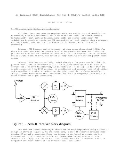
The receiver radio-frequency hardware can be much simplified using a Zero-IF<br />
design as shown on figure 1. On the other hand, a Zero-IF receiver requires more<br />
complex IF signal processing. Since the latter is performed at relatively low<br />
frequencies, it only requires simple and inexpensive hardware. <strong>BPSK</strong> or QPSK<br />
demodulation simply requires an additional phasor rotation to compensate for the<br />
frequency and phase offset of the receiver local oscillator.
A very successful 23cm Zero-IF <strong>BPSK</strong> transceiver design for 1.2Mbit/s was<br />
presented in [2], [4], [6] or [7]. This transceiver uses a Costas-loop <strong>BPSK</strong><br />
<strong>demodulator</strong>. The phasor rotation is achieved with a pair of rotating, analog CMOS<br />
switches, while the feedback loop is built as a digital PLL, as shown on figure 2.<br />
This design results in inexpensive and highly reproducible hardware with no tuning<br />
points.<br />
The measured bit-error rate performance of the described <strong>demodulator</strong> is<br />
compared to the theoretical performance of a <strong>BPSK</strong> <strong>demodulator</strong> on figure 3. The<br />
performance loss amounts to about 3...4dB and has many sources. About 0.7dB loss is<br />
caused by rotating the phasor in 16 discrete steps instead of a continuous phase<br />
adjustment. Less-than-ideal IF filtering accounts for at least 1dB of performance<br />
loss.<br />
Additional performance loss is caused by the switching transients caused by<br />
the analog CMOS switches and the non-ideal IF frequency response: the IQ dual IF<br />
amplifier can not be DC coupled for many practical reasons. The effects of the<br />
latter are particularly noticeable with longer pseudo-random test sequences.
With long test sequences, the performance of the <strong>demodulator</strong> may be even<br />
worse than shown on figure 3 in the particular case when the receiver LO frequency<br />
matches the transmitter frequency within a few kHz. In this particular case, the<br />
rotating switches toggle between two neighbor positions most of the time thus<br />
increasing the effects of switching glitches. The IF signal itself includes an<br />
increased DC component, corrupted by the AC-coupled dual IF amplifier.<br />
In this article, an improved <strong>BPSK</strong> <strong>demodulator</strong> is described that is completely<br />
compatible with the 23cm <strong>BPSK</strong> transceiver from [2], [4], [6] or [7]. The new<br />
<strong>demodulator</strong> completely solves the problem of switching transients and requires a<br />
lower gain IF amplifier, thus reducing the signal distortion. Finally, the new<br />
<strong>demodulator</strong> actually requires less components resulting in a simpler and cheaper<br />
circuit.
2. <strong>Improved</strong> <strong>BPSK</strong> <strong>demodulator</strong><br />
The operation of the new <strong>BPSK</strong> <strong>demodulator</strong> is also based on a phasor rotator<br />
with rotating switches with a block diagram similar to figure 2. The main<br />
difference from figure 2 is that the multiphase network drives a number of limiting<br />
amplifiers. The rotating switches are digital selectors and the switching<br />
transients can be removed easily with D-flip-flops.<br />
A phasor rotation in 16 discrete steps requires 16 limiting amplifiers and<br />
16-position switches. The actual hardware can be much simplified by considering<br />
that the second group of 8 limiting amplifiers provides just an inverted replica of<br />
the signals from the first group of 8 limiting amplifiers. Therefore just 8<br />
limiting amplifiers are required in the practical implementation, followed by 8position<br />
switches and finally EXOR gates to flip the phase of the signals when<br />
required.<br />
The analog part of the new <strong>BPSK</strong> <strong>demodulator</strong> is shown on figure 4. The IF<br />
signals I and Q and their inverted replicas, AC coupled from the dual IF amplifier,
drive a resistor network. Eight LM311 comparators are used as limiting amplifiers.<br />
Taps on the resistor network are selected to obtain eight signals with phases of 0,<br />
22.5, 45, 67.5, 90, 112.5, 135 and 157.5 degrees.<br />
The digital part of the new <strong>BPSK</strong> modulator is shown on figure 5. Two 74HC151<br />
multiplexers are used as rotating switches, operated with an offset of 90 degrees.<br />
The output signal phase can be further flipped with EXOR gates (74HC86 pins 1,2,3<br />
and 4,5,6) before the switching glitches are removed with the 74HC174 D-flip-flops.<br />
An EXOR gate (74HC86 pins 11,12,13) is also used to perform the signal<br />
multiplication, required for the feedback in a Costas loop.<br />
The bidirectional counter is identical to the one used in the old <strong>BPSK</strong><br />
<strong>demodulator</strong> and is built with two 74HC191 devices. The overall circuit was found to<br />
operate reliably up to clock frequencies of 20MHz. Since any switching glitches are<br />
completely removed by the D-flip-flops, the actual clock frequency can be increased<br />
from 6.144MHz to 14.3MHz, resulting in an increase of the carrier capture range<br />
from +/-24kHz up to about +/-56kHz.
The new <strong>BPSK</strong> <strong>demodulator</strong> is built on a double-sided printed-circuit board<br />
with the dimensions of 60mmX120mm. The component (top) side of the printed-circuit<br />
board is shown on figure 6 while the solder (bottom) side is shown on figure 7. The<br />
corresponding component location is shown on figure 8. The new <strong>BPSK</strong> <strong>demodulator</strong> has<br />
exactly the same dimensions and same electrical connections as the old one thus<br />
allowing a direct replacement of the old circuit.
Besides removing switching transients, the new <strong>demodulator</strong> has a much<br />
improved input sensitivity and dynamic range. The new <strong>demodulator</strong> will operate<br />
without any performance degradation with the input signals in the range from 30mVpp<br />
up to 3Vpp, corresponding to a dynamic range of 40dB. On the other hand, the old<br />
<strong>BPSK</strong> <strong>demodulator</strong> with the 74HC4067 analog switches required signals between 1Vpp<br />
and 3Vpp, corresponding to a dynamic range of only 10dB.
3. Modification of the Zero-IF amplifier<br />
The new <strong>BPSK</strong> <strong>demodulator</strong> on its own does not bring much improvement to the<br />
receiver performance, since most of the signal degradation occurs in the IQ dual IF<br />
amplifier. Thanks to its improved sensitivity and dynamic range, the new <strong>BPSK</strong><br />
<strong>demodulator</strong> requires less gain in the IF strip and has much released AGC<br />
requirements. Of course, the IQ dual IF amplifier has to be modified or better<br />
completely rebuilt to make use of the improved <strong>demodulator</strong>.<br />
The simplest solution is to modify the original IF amplifier as shown on<br />
figure 9. The original amplifier has three dual stages, while the new <strong>demodulator</strong><br />
only requires a single dual IF amplifier stage with a common AGC. Thanks to the<br />
improved dynamic range of the <strong>demodulator</strong>, the AGC remains inactive at low signal<br />
levels thus minimizing the signal distortion.<br />
The modified IQ dual IF amplifier can be built on the same printed-circuit<br />
board as presented in the original article [2], [4], [6] or [7]. Of course, only<br />
the components of first stage are installed, while the second and the third stage<br />
are simply bridged to the output symmetrical drivers. The values of some components<br />
are changed too. In particular the power-supply decoupling must be improved due to<br />
the lower signal levels required by the new <strong>BPSK</strong> <strong>demodulator</strong>.
A better solution is to redesign the IQ dual IF amplifier as shown on figure<br />
10. The latter uses two NE592 (or two uA733) video amplifiers that already have<br />
symmetric outputs as required by the <strong>BPSK</strong> <strong>demodulator</strong>. The new IQ dual IF amplifier<br />
is equipped with a faster AGC detector. The AGC voltage is made available on the<br />
output connector to drive a high-impedance (>50kohm) S-meter. The latter is useful<br />
during transceiver checkout or troubleshooting.<br />
The new IQ dual IF amplifier is built on a single-sided printed-circuit board<br />
with the dimensions of 40mmX120mm as shown on figure 11. The corresponding<br />
component location is shown on figure 12. The new printed-circuit board has the<br />
same length, but it is narrower than the old IF board. The electrical connectors<br />
are wired in the same way as in the old version, except for allocating an unused<br />
ground pin for the S-meter output.
Finally, it is recommended to apply some small modifications also to the<br />
quadrature IQ mixer module of the receiver, in particular to the input coupling of<br />
both IF preamplifiers. For clarity, figure 13 shows the modification of one of the<br />
two IF preamplifiers. First, the two quarter-wavelength chokes L19 and L20 on the<br />
original circuit diagram should be replaced with 47uH chokes to improve the<br />
rejection of out-of-band signals. Second, the coupling capacitors should be<br />
decreased from 4.7uF down to just 1uF to speed-up the receiver recovery after an<br />
input overload.
4. Practical applications of the <strong>BPSK</strong> radios<br />
The described Zero-IF strip and <strong>BPSK</strong> <strong>demodulator</strong> represent a further<br />
improvement to the already successful <strong>BPSK</strong> megabit packet-radio transceiver.<br />
Besides the improved performance, the modules shown on figures 14 and 15 also<br />
feature a reduced circuit complexity and component count. Both modules were also<br />
tested successfully in a 13cm version of the Zero-IF <strong>BPSK</strong> transceiver to be<br />
published in a future article.<br />
In order to increase the throughput of a packet-radio network, besides<br />
increasing the transmission speed it is also necessary to increase the frame length<br />
beyond the standard limit of 256 bytes. The current choice is 1500 bytes to<br />
transport standard IP frames without fragmentation and is already implemented in<br />
the megabit TNC shown in [8] or [9].
Longer frames are more sensitive to transmission errors. Therefore improving<br />
the <strong>demodulator</strong> performance is even more important with longer frames. If the<br />
(otherwise efficient) datagram mode is used to transmit IP frames through the AX.25<br />
network, lost frames can only be recovered by the relatively slow TCP retries.<br />
More than one hundred 1.2Mbit/s <strong>BPSK</strong> radios for both 23cm and 13cm have been<br />
built in Slovenia, Italy and Croatia. Practically the whole Slovenian packet radio<br />
network shown on figure 16 is now based on the Zero-IF <strong>BPSK</strong> transceivers, with many<br />
more nodes in Italy and Croatia adding to the list. While upgrading the network<br />
from 256byte frames to MTU 1500, some additional margin on the radio links was<br />
required and the latter was a good reason for developing an improved <strong>BPSK</strong><br />
<strong>demodulator</strong>.<br />
Since the megabit packet-radio network is available, digital ATV is becoming<br />
increasingly more popular, using inexpensive "web" cameras and personal computers.<br />
In order to obtain a good-quality, live color picture with programs like Microsoft<br />
Netmeeting, the RS-232 interface to the TNC has to be modified to at least<br />
460kbit/s, resulting in data flows of about 30kbytes/s.<br />
With these data flows, the current packet-radio network, based on 1.2Mbit/s<br />
radios, quickly approaches congestion. One already has to think about the next<br />
step, interlinks in the 10 to 20Mbit/s range. The described <strong>BPSK</strong> <strong>demodulator</strong> could<br />
in principle work at higher speeds by using faster comparators and faster logic.<br />
The best idea is probably to burn the whole digital circuit into a fieldprogrammable<br />
logic array.<br />
On the other hand, efficient and reliable <strong>BPSK</strong> <strong>demodulator</strong>s are also required<br />
for satellite communications. Although the increased free-space insertion loss and<br />
tight power budget limit the data rate to less than 1Mbit/s for amateur satellites,<br />
simple and reliable hardware solutions are preferred to DSP, especially in a
adiation environment like space. The described <strong>BPSK</strong> <strong>demodulator</strong> can be easily<br />
modified for lower data rates, including the 153.6kbit/s <strong>BPSK</strong> "RUDAK" output from<br />
AO-40.
References:<br />
[1] Matjaž Vidmar: "1.2Mbit/s SuperVozelj packet-radio node system", Scriptum<br />
der Vortraege, 40. Weinheimer UKW Tagung, Weinheim, Germany, 16-17 September 1995,<br />
pages 240-252.<br />
[2] Matjaz Vidmar: "23cm PSK Packet-radio TRX for 1.2Mbit/s user access", Scriptum<br />
der Vortraege, 41. Weinheimer UKW Tagung, Weinheim, Germany, 21-22 September 1996,<br />
pages 25.1-25.15.<br />
[3] Matjaž Vidmar: "13cm PSK Transceiver for 1.2Mbit/s Packet Radio", 15th ARRL and<br />
TAPR DIGITAL COMMUNICATIONS CONFERENCE, Seattle, Washington, USA, September 20-22,<br />
1996, pages 145-175.<br />
[4] Matjaž Vidmar: "23cm PSK Packet-Radio RTX for 1.2Mbit/s User Access", 15th ARRL<br />
and TAPR DIGITAL COMMUNICATIONS CONFERENCE, Seattle, Washington, USA, September<br />
20-22, 1996, pages 176-202.<br />
[5] Matjaž Vidmar: "13cm PSK Transceiver for 1.2Mbits/s Packet Radio", Part-1, VHF-<br />
Communications 3/1996, pages 130-147. Part-2, VHF-Communications 4/1996, pages 194-<br />
205.<br />
[6] Matjaž Vidmar: "23-cm-Packet-Radio-Transceiver fuer 1.2-Mbit/s-<br />
Benutzerzugriffe", Part-1, AMSAT-DL Journal 3/1996, pages 42-44. Part-2, AMSAT-DL<br />
Journal 4/1996, pages 11-26.<br />
[7] Matjaž Vidmar: "23cm PSK Packet Radio Transceiver for 1.2Mbit/s User access",<br />
VHF-Communications 2/1997, pages 74-96.<br />
[8] Matjaž Vidmar: 'A simple TNC for megabit packet-radio links', Skriptum der<br />
Vortraege, 45. Weinheimer UKW Tagung, Weinheim, Germany, 9-10 September 2000, pages<br />
28.1-28.19.<br />
[9] Matjaž Vidmar: "A simple TNC for megabit packet-radio links', VHF-<br />
Communications 3/2000, pages 137-151.<br />
* * *