

Chapter 5 Advanced Cisco Catalyst Switch Troubleshooting
Chapter 5 Advanced Cisco Catalyst Switch Troubleshooting
Chapter 5 Advanced Cisco Catalyst Switch Troubleshooting

Create successful ePaper yourself
Turn your PDF publications into a flip-book with our unique Google optimized e-Paper software.
<strong>Chapter</strong> 5 <strong>Advanced</strong> <strong>Cisco</strong> <strong>Catalyst</strong> <strong>Switch</strong><br />
<strong>Troubleshooting</strong><br />
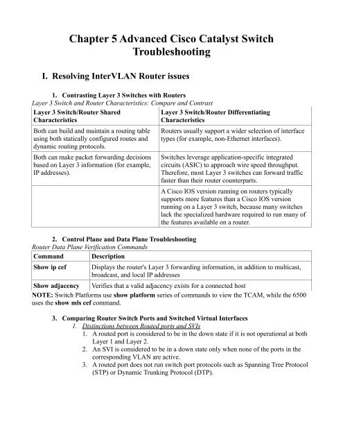
I. Resolving InterVLAN Router issues<br />
1. Contrasting Layer 3 <strong>Switch</strong>es with Routers<br />
Layer 3 <strong>Switch</strong> and Router Characteristics: Compare and Contrast<br />
Layer 3 <strong>Switch</strong>/Router Shared<br />
Layer 3 <strong>Switch</strong>/Router Differentiating<br />
Characteristics<br />
Characteristics<br />
Both can build and maintain a routing table<br />
using both statically configured routes and<br />
dynamic routing protocols.<br />
Both can make packet forwarding decisions<br />
based on Layer 3 information (for example,<br />
IP addresses).<br />
2. Control Plane and Data Plane <strong>Troubleshooting</strong><br />
Router Data Plane Verification Commands<br />
Command Description<br />
Routers usually support a wider selection of interface<br />
types (for example, non-Ethernet interfaces).<br />
<strong>Switch</strong>es leverage application-specific integrated<br />
circuits (ASIC) to approach wire speed throughput.<br />
Therefore, most Layer 3 switches can forward traffic<br />
faster than their router counterparts.<br />
A <strong>Cisco</strong> IOS version running on routers typically<br />
supports more features than a <strong>Cisco</strong> IOS version<br />
running on a Layer 3 switch, because many switches<br />
lack the specialized hardware required to run many of<br />
the features available on a router.<br />
Show ip cef Displays the router's Layer 3 forwarding information, in addition to multicast,<br />
broadcast, and local IP addresses<br />
Show adjacency Verifies that a valid adjacency exists for a connected host<br />
NOTE: <strong>Switch</strong> Platforms use show platform series of commands to view the TCAM, while the 6500<br />
uses the show mls cef command.<br />
3. Comparing Router <strong>Switch</strong> Ports and <strong>Switch</strong>ed Virtual Interfaces<br />
1. Distinctions between Routed ports and SVIs<br />
1. A routed port is considered to be in the down state if it is not operational at both<br />
Layer 1 and Layer 2.<br />
2. An SVI is considered to be in a down state only when none of the ports in the<br />
corresponding VLAN are active.<br />
3. A routed port does not run switch port protocols such as Spanning Tree Protocol<br />
(STP) or Dynamic Trunking Protocol (DTP).
II.Router Redundancy <strong>Troubleshooting</strong><br />
1. HSRP<br />
1. Active and Standby Router uses a virtual IP and MAC address<br />
1. Active – Services requests destined to the virtual IP and MAC address.<br />
2. Standby – Waits for the Active switch to go down.<br />
1. Higher Priority is better<br />
2. Configure Preempt on a switch so that it will take over the active role<br />
immediately if priority is better on which you configured preempt.<br />
2. Converging After a Router Failure<br />
1. HSRP hello timer every 3 seconds<br />
2. HSRP dead timer is 10 seconds<br />
3. If interface administratively shutdown, switch/router send a resign message and<br />
other switch/router takes over the active role.<br />
4. If a new switch/router is added to the network with a higher priority then the<br />
other switch/routers and with preempt configured, it will send a coup message<br />
and take over the active role.<br />
3. HSRP Verification and <strong>Troubleshooting</strong><br />
1. Information to look for when checking config or troubleshooting<br />
1. Which route is the active router<br />
2. Which routers, if any, are configured with the preempt option<br />
3. What is the virtual IP address<br />
4. What is the virtual MAC address<br />
2. Show commands<br />
1. show standby brief – shows virtual ip, active/standby preempt group interface...<br />
2. show standby type mod/num – shows detailed information, including virtual<br />
MAC.<br />
3. Virtual MAC format for HSRP<br />
1. 0000.0c07.ac – first 40 bits indicates HSRP<br />
2. 00 to FF – last 8 bits (meaning last 2 hex digits) indicates group number.<br />
3. Example: 0000.0c07.ac0a = HSRP group 10<br />
4. Use a host to verify virtual IP and MAC<br />
1. Ping the virtual IP<br />
2. check the ARP cache of a host on the same subnet as the virtual HSRP IP to<br />
ensure it has the right virtual MAC in it's ARP cache.<br />
3. Debug standby terse – use to view important HSRP changes in real time.<br />
4. VRRP<br />
1. Virtual Router Master and Virtual Router Backups<br />
1. Unlike HSRP, VRRP can use the IP address of a configured physical interface as<br />
the virtual IP.
5. GLBP<br />
1. There is one AVG and multiple AVFs (Active Virtual Gateway and Active Virtual<br />
Forwarders)<br />
1. AVG is responsible for responding to ARPs and sending the virtual MAC of each<br />
AVF including it's own; by default using round robin for load balancing.<br />
6. <strong>Troubleshooting</strong> VRRP and GLBP<br />
1. Common show commands<br />
1. show vrrp brief<br />
2. show glbp brief<br />
Comparing HSRP, VRRP, and GLBP<br />
Characteristic HSRP VRRP GLBP<br />
<strong>Cisco</strong> Proprietary Yes No Yes<br />
Interface IP address can<br />
act as virtual IP address<br />
More than one router in<br />
a group can<br />
simultaneously forward<br />
traffic for that group<br />
Hello timer default<br />
value<br />
No Yes No<br />
No No Yes<br />
3 1 3<br />
III. <strong>Cisco</strong> <strong>Catalyst</strong> <strong>Switch</strong> Performance <strong>Troubleshooting</strong><br />
1. <strong>Cisco</strong> <strong>Catalyst</strong> <strong>Switch</strong> <strong>Troubleshooting</strong> Targets<br />
1. Various <strong>Switch</strong> Platforms, but major similarities are:<br />
1. Ports – A switch's ports physically connect the switch to other network devices<br />
These ports (also known as interfaces) allow a switch to receive and transmit<br />
traffic<br />
2. Forwarding Logic – A switch contains hardware that makes forwarding<br />
decisions. This hardware rewrites a frame's headers.<br />
3. Backplane – A switch's backplane physically interconnects a switch's ports.<br />
Therefore, depending on the specific switch architecture, frames flowing through<br />
a switch enter via a port (that is, the ingress port), flow across a switch's<br />
backplane, and are forwarded out of another port (that is, an egress port.)<br />
4. Control plane – A switch's CPU and memory reside in a control plane. This<br />
control plane is responsible for running the switch's operating system.<br />
2. Common troubleshooting Targets<br />
1. Port Errors<br />
2. Mismatched duplex settings
2. Port Errors<br />
1. If a TCP application is running slow:<br />
1. TCP slow start – caused by dropped packets, reducing the window size of the<br />
TCP flow.<br />
2. Show commands for port stats and errors<br />
1. show interfaces<br />
2. show interfaces type mod/num counters<br />
3. show interfaces type mod/num counters errors<br />
Errors in the show interfaces type mod/num counters errors Command<br />
Error Counter Description<br />
Align-Err An alignment error occurs when frames do not end with an even number of octets,<br />
while simultaneously having a bad Cyclic Redundancy Check (CRC). An<br />
alignment error normally suggests a Layer 1 issue, such as cabling or port (either<br />
switch port or NIC port) issues.<br />
FCS-Err A Frame Check Sequence (FCS) error occurs when a frame has an invalid<br />
checksum, although the frame has no framing errors. Like the Align-Err error, an<br />
FCS-Err often points to a Layer 1 issue.<br />
Xmit-Err A transmit error (Xmit-Err) occurs when a port's transmit buffer overflows. A<br />
speed mismatch between inbound and outbound links often results in a transmit<br />
error.<br />
Rcv-Err A receive error (Rcv-Err) occurs when a port's receive buffer overflows.<br />
Congestion on a switch's backplane could cause the receive buffer on a port to fill<br />
to capacity, as frames await access to the switch's backplane. However, most<br />
likely, a Rcv-Err is indicating a duplex mismatch.<br />
UnderSize An Undersize frame is a frame with a valid checksum but a size less than 64 bytes.<br />
This issue suggests that a connected host is sourcing invalid frame sizes.<br />
Single-Col A Single-Col error occurs when a single collision occurs before a port successfully<br />
transmits a frame. High bandwidth utilization on an attached link or a duplex<br />
mismatch are common reasons for a Single-Col error.<br />
Multi-Col A Multi-Col error occurs when more than one collision occurs before a port<br />
successfully transmits a frame. Similar to the Single-Col error, high bandwidth<br />
utilization on an attached link or a duplex mismatch are common reasons for a<br />
Multi-Col error.<br />
Late-Col A late collision is a collision that is not detected until well after the frame has<br />
begun to be forwarded. While a Late-Col error could indicate that the connected<br />
cable is too long, this is an extremely common error seen in mismatched duplex<br />
conditions.<br />
Excess-Col The Excess-Col error occurs when a frame experienced sixteen successive<br />
collisions, after which the frame was dropped. This error could result from high<br />
bandwidth utilization, a duplex mismatch, or too many devices on a segment.<br />
Carri-Sen The Carri-Sen counter is incremented when a port wants to send data on a halfduplex<br />
link. This is normal and expected on a half-duplex port, because the port is<br />
checking the wire, to make sure no traffic is present, prior to sending a frame. This<br />
operation is the carrier sense procedure described by the Carrier Sense Multiple
Access with Collision Detect (CSMA/CD) operation used on half-duplex<br />
connections. Full-duplex connections, however, do not use CSMA/CD.<br />
Runts A runt is a frame that is less than 64 bytes in size and has a bad CRC. A runt could<br />
result from a duplex mismatch or a Layer 1 issue.<br />
Giants A giant is a frame size greater than 1518 bytes (assuming the frame is not a jumbo<br />
frame) that has a bad FCS. Typically, a giant is caused by a problem with the NIC<br />
in an attached host.<br />
3. Mismatched Duplex Settings<br />
1. No hubs, no half-duplex!<br />
2. <strong>Cisco</strong> Best Practice for Port Speed/Duplex<br />
1. If a connected device only supported half-duplex, it would be better for a switch<br />
port to negotiate down to half-duplex and run properly than being forced to run<br />
full-duplex which would result in multiple errors<br />
2. The automatic medium-dependent interface crossover (auto-MDIX) feature can<br />
automatically detect if a port needs a crossover or a straight-through cable to<br />
interconnect with an attached device and adjust the port to work regardless of<br />
which cable type is connected. You can enable this feature in interface<br />
configuration mode with the mdix auto command on some models of <strong>Cisco</strong><br />
<strong>Catalyst</strong> switches. However, the auto-MDIX feature requires that the port<br />
autonegotiate both speed and duplex.<br />
3. NOTE: Also from personal experience, it can be useful to use autonegotiate to<br />
diagnose physical problems. For example when you know the speed should<br />
negotiate to 1Gbps, but instead it negotiates to 10Mbps. This can indicate a<br />
cable or NIC problem; or a configuration issue on the host side. When you use<br />
autonegotiate it allows you, depending on what the switch negotiates to, to figure<br />
out what the host is configured to use. For instance if you are using<br />
autonegotiate on a 10/100/1000 interface, and the interface ends up negotiating<br />
to 100/half duplex, then you can assume that either the NIC of the host is<br />
configured for 100Mbps and either half or full duplex. Remember that when you<br />
manually configure the duplex on one side this disables the negotiation of<br />
duplex. This switch will then send messages to try and negotiate duplex but not<br />
receive any from the host, and the switch will end up defaulting to half-duplex. If<br />
this isn't the issue, then there is something wrong with the host, either hardware<br />
issues or bad drivers for the NIC.<br />
3. Likely errors seen on full duplex side and half duplex side<br />
1. Full Duplex – Rcv-Err count<br />
2. Half Duplex – Late-Col<br />
4. How to troubleshoot a duplex mismatch without access to the host (or other device)<br />
1. A good way to troubleshoot with only access to one side is:<br />
1. First, number 3 above<br />
2. Second, try changing the duplex and clear the counters of the interface and<br />
see if the errors continue.
2. TCAM <strong>Troubleshooting</strong><br />
1. TCAM (Ternary Content Addressable Memory) works with CEF to forward data<br />
extremely fast. TCAM is part of the forwarding hardware. If for some reason the<br />
TCAM is not usable, the data is punted to the CPU for processing, which is not as<br />
fast.<br />
2. Reasons to punt to the CPU include:<br />
1. Routing protocols, in addition to other control plane protocols such as STP, that<br />
send multicast or broadcast traffic will have that traffic sent to the CPU.<br />
2. Someone connected to a switch administratively (for example, establishing a<br />
Telnet session with the switch) will have their packets sent to the CPU.<br />
3. Packets using a feature not supported in hardware (for example, packets<br />
traveling over a GRE tunnel) are sent to the CPU. (ARP is also an example)<br />
4. If a switch's TCAM has reached capacity, additional packets will be punted to<br />
the CPU. A TCAM might reach capacity if it has too many installed routes or<br />
configured access control lists.<br />
3. Most likely the reason for poor performance is that the TCAM fills to capacity.<br />
1. Show commands vary from platform to platform, examples:<br />
1. 3550 – show tcam inacl 1 statistics<br />
2. 3560 and 3750 – show platform tcam<br />
2. Show command to see how many packets are being punted to the CPU<br />
1. show controllers cpu-interface<br />
3. High CPU Utilization Level <strong>Troubleshooting</strong><br />
1. CPU utilization is usually low due to the TCAM as the TCAM maintains the switch's<br />
forwarding logic.<br />
2. Show command to view CPU utilization<br />
1. show processes cpu<br />
3. High CPU utilization spikes aren't an issue if can be explained, reasons include:<br />
1. The CPU processing routing updates<br />
2. Issuing a debug command (or other processor-intensive commands)<br />
3. SNMP being used to poll network devices<br />
4. If you determine that a switch's high CPU load is primarily the result of interrupts,<br />
you should examine the switch's packet switching patterns and check the TCAM<br />
utilization. If, however, the high CPU utilization is primarily the result of processes,<br />
you should investigate those specific processes. A high CPU utilization on a switch<br />
might be a result of STP. Recall that an STP failure could lead to a broadcast storm,<br />
where Layer 2 broadcast frames endlessly circulate through a network. Therefore,<br />
when troubleshooting a performance issue, realize that a switch's hgih CPU<br />
utilization might be a symptom of another issue.


