

Activity 6.4.1: Basic VLSM Calculation and Addressing Design
Activity 6.4.1: Basic VLSM Calculation and Addressing Design
Activity 6.4.1: Basic VLSM Calculation and Addressing Design

You also want an ePaper? Increase the reach of your titles
YUMPU automatically turns print PDFs into web optimized ePapers that Google loves.
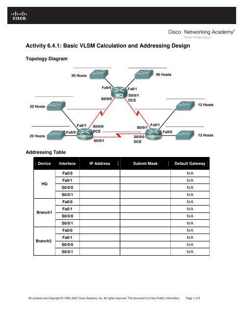
<strong>Activity</strong> <strong>6.4.1</strong>: <strong>Basic</strong> <strong>VLSM</strong> <strong>Calculation</strong> <strong>and</strong> <strong>Addressing</strong> <strong>Design</strong><br />
Topology Diagram<br />
<strong>Addressing</strong> Table<br />
Device Interface IP Address Subnet Mask Default Gateway<br />
HQ<br />
Branch1<br />
Branch2<br />
Fa0/0 N/A<br />
Fa0/1 N/A<br />
S0/0/0 N/A<br />
S0/0/1 N/A<br />
Fa0/0 N/A<br />
Fa0/1 N/A<br />
S0/0/0 N/A<br />
S0/0/1 N/A<br />
Fa0/0 N/A<br />
Fa0/1 N/A<br />
S0/0/0 N/A<br />
S0/0/1 N/A<br />
All contents are Copyright © 1992–2007 Cisco Systems, Inc. All rights reserved. This document is Cisco Public Information. Page 1 of 5
CCNA Exploration<br />
Routing Protocols <strong>and</strong> Concepts:<br />
<strong>VLSM</strong> <strong>and</strong> CIDR <strong>Activity</strong> <strong>6.4.1</strong>: <strong>Basic</strong> <strong>VLSM</strong> <strong>Calculation</strong> <strong>and</strong> <strong>Addressing</strong> <strong>Design</strong><br />
Learning Objectives<br />
Upon completion of this activity, you will be able to:<br />
• Determine the number of subnets needed.<br />
• Determine the number of hosts needed for each subnet<br />
• <strong>Design</strong> an appropriate addressing scheme using <strong>VLSM</strong>.<br />
• Assign addresses <strong>and</strong> subnet mask pairs to device interfaces.<br />
• Examine the use of the available network address space.<br />
Scenario<br />
In this activity, you have been given the network address 192.168.1.0/24 to subnet <strong>and</strong> provide the IP<br />
addressing for the network shown in the Topology Diagram. <strong>VLSM</strong> will be used so that the addressing<br />
requirements can be met using the 192.168.1.0/24 network. The network has the following addressing<br />
requirements:<br />
• The HQ LAN1 will require 50 host IP addresses.<br />
• The HQ LAN2 will require 50 host IP addresses.<br />
• The Branch1 LAN1 will require 20 host IP addresses.<br />
• The Branch1 LAN2 will require 20 host IP addresses<br />
• The Branch2 LAN1 will require 12 host IP addresses.<br />
• The Branch2 LAN2 will require 12 host IP addresses.<br />
• The link from HQ to Branch1 will require an IP address for each end of the link.<br />
• The link from HQ to Branch2 will require an IP address for each end of the link.<br />
• The link Branch1 to Branch2 will require an IP address for each end of the link.<br />
Task 1: Examine the Network Requirements.<br />
Examine the network requirements <strong>and</strong> answer the questions below. Keep in mind that IP addresses will<br />
be needed for each of the LAN interfaces.<br />
1. How many subnets are needed? _______<br />
2. What is the maximum number of IP addresses that are needed for a single subnet? _______<br />
3. How many IP addresses are needed for each of the BranchBranch1 LANs? _______<br />
4. How many IP addresses are needed for each of the BranchBranch2 LANs? _______<br />
5. How many IP addresses are needed for each of the WAN links between routers? _______<br />
6. What is the total number of IP addresses that are needed? _______<br />
7. What is the total number of IP addresses that are available in the 192.168.1.0/24 network?<br />
_______<br />
8. Can the network addressing requirements be met using the 192.168.1.0/24 network? _______<br />
Task 2: <strong>Design</strong> an IP <strong>Addressing</strong> Scheme<br />
Step 1: Determine the subnet information for the largest network segment or segments.<br />
In this case, the two HQ LANs are the largest subnets.<br />
All contents are Copyright © 1992–2007 Cisco Systems, Inc. All rights reserved. This document is Cisco Public Information. Page 2 of 5
CCNA Exploration<br />
Routing Protocols <strong>and</strong> Concepts:<br />
<strong>VLSM</strong> <strong>and</strong> CIDR <strong>Activity</strong> <strong>6.4.1</strong>: <strong>Basic</strong> <strong>VLSM</strong> <strong>Calculation</strong> <strong>and</strong> <strong>Addressing</strong> <strong>Design</strong><br />
1. How many IP addresses are needed for each LAN? _______<br />
2. What is the smallest size subnet that can be used to meet this requirement? _______<br />
3. What is the maximum number of IP addresses that can be assigned in this size subnet? _______<br />
Step 2: Assign subnets to HQ LANs.<br />
Start at the beginning of the 192.168.1.0/24 network.<br />
1. Assign the first available subnet to HQ LAN1.<br />
2. Fill in the chart below with the appropriate information.<br />
HQ LAN1 Subnet<br />
Network<br />
Address<br />
Decimal<br />
Subnet Mask<br />
CIDR Subnet<br />
Mask<br />
3. Assign the next available subnet to HQ LAN2.<br />
First Usable IP<br />
Address<br />
4. Fill in the chart below with the appropriate information.<br />
HQ LAN2 Subnet<br />
Network<br />
Address<br />
Decimal<br />
Subnet Mask<br />
CIDR Subnet<br />
Mask<br />
First Usable IP<br />
Address<br />
Last Usable IP<br />
Address<br />
Last Usable IP<br />
Address<br />
Broadcast<br />
Address<br />
Broadcast<br />
Address<br />
Step 3: Determine the subnet information for the next largest network segment or segments.<br />
In this case, the two Branch1 LANs are the next largest subnets.<br />
1. How many IP addresses are needed for each LAN? _______<br />
2. What is the smallest size subnet that can be used to meet this requirement? _______<br />
3. What is the maximum number of IP addresses that can be assigned in this size subnet? _______<br />
30<br />
Step 4: Assign subnet to BRANCH1 LANs.<br />
Start with the IP address following the HQ LAN subnets.<br />
1. Assign the next subnet to Branch1 LAN1.<br />
2. Fill in the chart below with the appropriate information.<br />
Branch1 LAN1 Subnet<br />
Network<br />
Address<br />
Decimal<br />
Subnet Mask<br />
CIDR Subnet<br />
Mask<br />
3. Assign the next available subnet to Branch1 LAN2.<br />
First Usable IP<br />
Address<br />
Last Usable IP<br />
Address<br />
Broadcast<br />
Address<br />
All contents are Copyright © 1992–2007 Cisco Systems, Inc. All rights reserved. This document is Cisco Public Information. Page 3 of 5
CCNA Exploration<br />
Routing Protocols <strong>and</strong> Concepts:<br />
<strong>VLSM</strong> <strong>and</strong> CIDR <strong>Activity</strong> <strong>6.4.1</strong>: <strong>Basic</strong> <strong>VLSM</strong> <strong>Calculation</strong> <strong>and</strong> <strong>Addressing</strong> <strong>Design</strong><br />
4. Fill in the chart below with the appropriate information.<br />
Branch1 LAN2 Subnet<br />
Network<br />
Address<br />
Decimal<br />
Subnet Mask<br />
CIDR Subnet<br />
Mask<br />
First Usable IP<br />
Address<br />
Last Usable IP<br />
Address<br />
Broadcast<br />
Address<br />
Step 5: Determine the subnet information for the next largest network segment or segments.<br />
In this case, the two Branch2 LANs are the next largest subnets.<br />
1. How many IP addresses are needed for each LAN? _______<br />
2. What is the smallest size subnet that can be used to meet this requirement? _______<br />
3. What is the maximum number of IP addresses that can be assigned in this size subnet? _______<br />
Step 6: Assign subnets to BRANCH2 LANs.<br />
Start with the IP address following the Branch1 LAN subnets.<br />
1. Assign the next subnet to the Branch2 LAN1. Fill in the chart below with the appropriate<br />
information.<br />
Branch2 LAN1 Subnet<br />
Network<br />
Address<br />
Decimal<br />
Subnet Mask<br />
CIDR Subnet<br />
Mask<br />
2. Assign the next available subnet to Branch2 LAN2.<br />
First Usable IP<br />
Address<br />
3. Fill in the chart below with the appropriate information.<br />
Branch2 LAN2 Subnet<br />
Network<br />
Address<br />
Decimal<br />
Subnet Mask<br />
CIDR Subnet<br />
Mask<br />
First Usable IP<br />
Address<br />
Last Usable IP<br />
Address<br />
Last Usable IP<br />
Address<br />
Step 7: Determine the subnet information for the links between the routers.<br />
1. How many IP addresses are needed for each link? _______<br />
2. What is the smallest size subnet that can be used to meet this requirement? _______<br />
Broadcast<br />
Address<br />
Broadcast<br />
Address<br />
3. What is the maximum number of IP addresses that can be assigned in this size subnet? _______<br />
Step 8: Assign subnets to links.<br />
Start with the IP address following the Branch2 LAN subnets.<br />
1. Assign the next available subnet to the link between the HQ <strong>and</strong> Branch1 routers.<br />
2. Fill in the chart below with the appropriate information.<br />
Link between HQ <strong>and</strong> Branch1 Subnet<br />
Network<br />
Address<br />
Decimal<br />
Subnet Mask<br />
CIDR Subnet<br />
Mask<br />
First Usable IP<br />
Address<br />
Last Usable IP<br />
Address<br />
Broadcast<br />
Address<br />
All contents are Copyright © 1992–2007 Cisco Systems, Inc. All rights reserved. This document is Cisco Public Information. Page 4 of 5
CCNA Exploration<br />
Routing Protocols <strong>and</strong> Concepts:<br />
<strong>VLSM</strong> <strong>and</strong> CIDR <strong>Activity</strong> <strong>6.4.1</strong>: <strong>Basic</strong> <strong>VLSM</strong> <strong>Calculation</strong> <strong>and</strong> <strong>Addressing</strong> <strong>Design</strong><br />
3. Assign the next available subnet to the link between the HQ <strong>and</strong> Branch2 routers.<br />
4. Fill in the chart below with the appropriate information.<br />
Link between HQ <strong>and</strong> Branch2 Subnet<br />
Network<br />
Address<br />
Decimal<br />
Subnet Mask<br />
CIDR Subnet<br />
Mask<br />
First Usable IP<br />
Address<br />
Last Usable IP<br />
Address<br />
5. Assign the next available subnet to the link between the Branch1 <strong>and</strong> Branch2 routers.<br />
6. Fill in the chart below with the appropriate information.<br />
Link between Branch1 <strong>and</strong> Branch2 Subnet<br />
Network<br />
Address<br />
Decimal<br />
Subnet Mask<br />
CIDR Subnet<br />
Mask<br />
Task 3: Assign IP Addresses to the Network Devices<br />
First Usable IP<br />
Address<br />
Last Usable IP<br />
Address<br />
Broadcast<br />
Address<br />
Broadcast<br />
Address<br />
Assign the appropriate addresses to the device interfaces. Document the addresses to be used in the<br />
<strong>Addressing</strong> Table provided under the Topology Diagram.<br />
Step 1: Assign addresses to the HQ router.<br />
1. Assign the first valid host address in the HQ LAN 1 subnet to the Fa0/0 LAN interface.<br />
2. Assign the first valid host address in the HQ LAN 2 subnet to the Fao/1 LAN interface.<br />
3. Assign the first valid host address in the link between HQ <strong>and</strong> Branch1 subnet to the S0/0/0<br />
interface.<br />
4. Assign the first valid host address in the link between HQ <strong>and</strong> Branch2 subnet to the S0/0/1<br />
interface.<br />
Step 2: Assign addresses to the Branch1 router.<br />
1. Assign the first valid host address in the Branch1 LAN1 subnet to the Fa0/0 LAN interface.<br />
2. Assign the first valid host address in the Branch1 LAN2 subnet to the Fa0/1 LAN interface.<br />
3. Assign the last valid host address on the link between Branch1 <strong>and</strong> HQ subnet to the S0/0/0<br />
interface<br />
4. Assign the first valid host address on the link between Branch1 <strong>and</strong> Branch2 subnet to the S0/0/1<br />
interface.<br />
Step 3: Assign addresses to the Branch2 router.<br />
1. Assign the first valid host address in the Branch2 LAN1 subnet to the Fa0/0 LAN interface.<br />
2. Assign the first valid host address in the Branch 2 LAN 2 subnet to the Fa0/1 LAN interface.<br />
3. Assign the last valid host address on the link between HQ <strong>and</strong> Branch2 subnet to the S0/0/1<br />
interface<br />
4. Assign the last valid host address on the link between Branch1 <strong>and</strong> Branch2 subnet to the S0/0/0<br />
interface.<br />
All contents are Copyright © 1992–2007 Cisco Systems, Inc. All rights reserved. This document is Cisco Public Information. Page 5 of 5


