

Frame Relay Point-to-Point Lab - The Cisco Learning Network
Frame Relay Point-to-Point Lab - The Cisco Learning Network
Frame Relay Point-to-Point Lab - The Cisco Learning Network

Create successful ePaper yourself
Turn your PDF publications into a flip-book with our unique Google optimized e-Paper software.
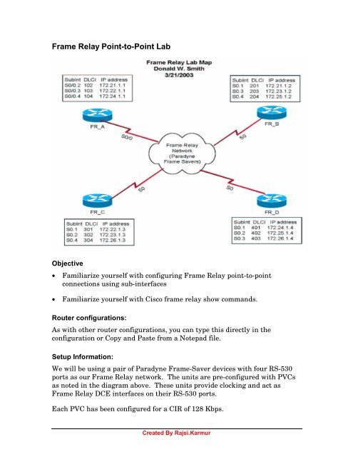
<strong>Frame</strong> <strong>Relay</strong> <strong>Point</strong>-<strong>to</strong>-<strong>Point</strong> <strong>Lab</strong><br />
Objective<br />
• Familiarize yourself with configuring <strong>Frame</strong> <strong>Relay</strong> point-<strong>to</strong>-point<br />
connections using sub-interfaces<br />
• Familiarize yourself with <strong>Cisco</strong> frame relay show commands.<br />
Router configurations:<br />
As with other router configurations, you can type this directly in the<br />
configuration or Copy and Paste from a Notepad file.<br />
Setup Information:<br />
We will be using a pair of Paradyne <strong>Frame</strong>-Saver devices with four RS-530<br />
ports as our <strong>Frame</strong> <strong>Relay</strong> network. <strong>The</strong> units are pre-configured with PVCs<br />
as noted in the diagram above. <strong>The</strong>se units provide clocking and act as<br />
<strong>Frame</strong> <strong>Relay</strong> DCE interfaces on their RS-530 ports.<br />
Each PVC has been configured for a CIR of 128 Kbps.<br />
Created By Rajsi.Karmur
Physical Connections and Port Setup<br />
Connect your router Serial port 0 <strong>to</strong> the appropriate interface on the <strong>Frame</strong>-<br />
Saver switches using a DB-60 <strong>to</strong> RS-530 cable (provided by your instruc<strong>to</strong>r):<br />
Router <strong>Frame</strong> Saver Port<br />
<strong>Lab</strong>_A (FR_A) 1 1<br />
<strong>Lab</strong>_B (FR_B) 1 2<br />
<strong>Lab</strong>_C (FR_C) 2 1<br />
<strong>Lab</strong>_D (FR_D) 2 2<br />
.<br />
Step 1 Start with a “clean” configuration (erase start and reboot).<br />
Step 2 Set the host name <strong>to</strong> FR_x. ( x = A, B, C or D)<br />
Step 3 Configure S0 <strong>to</strong> support <strong>Frame</strong> <strong>Relay</strong> IETF encapsulation.<br />
Enable the interface.<br />
Step 4 Wait about 1 minute and see if your router has received<br />
information from the switch regarding active DLCIs. Use the<br />
following commands and note any interesting results:<br />
Step 5 Show frame lmi<br />
What LMI Pro<strong>to</strong>col are the switches using? (Circle one):<br />
<strong>Cisco</strong> ITU-T Q.933a ANSI T1.617 Annex D<br />
Step 7 Show interface s0 – Record the following<br />
LMI enq sent ___, LMI stat recvd ___, LMI upd recvd ___, DTE LMI up<br />
LMI enq recvd ___, LMI stat sent ___, LMI upd sent ___<br />
LMI DLCI ___ LMI type is ___ frame relay DTE<br />
Step 8 Try Show <strong>Frame</strong> PVC and list all known DLCIs:<br />
________________________________________________________________<br />
Example:<br />
DLCI = 18, DLCI USAGE = LOCAL, PVC STATUS = ACTIVE, INTERFACE = Serial0<br />
Step 9 How did your router learn of these DLCIs?<br />
_____________________________________<br />
Created By Rajsi.Karmur
Sub-Interface Configuration<br />
Setup DLCIs <strong>to</strong> other routers on Sub-Interfaces based on the “<strong>Frame</strong><br />
<strong>Relay</strong> <strong>Lab</strong> Map” using the following sequences of commands.<br />
WARNING: Do NOT use sub-interface S0.0 – it is the “base” interface<br />
For each <strong>Frame</strong> <strong>Relay</strong> sub-interface on your router:<br />
Step 1 Create a sub-interface from interface configuration mode using<br />
the int S0.1 point command. (Note: <strong>The</strong> point forces the<br />
interface <strong>to</strong> point-<strong>to</strong>-point mode)<br />
Step 2 Assign the frame relay DLCI o this sub-interface based on the<br />
table for your router: frame interface-dlci xxx<br />
Step 3 Assign the IP address <strong>to</strong> this sub-interface based on the table for<br />
your router with a class B mask: ip address a.b.c.d 255.255.0.0<br />
STOP! Wait for other members of your lab team <strong>to</strong><br />
complete their sub-interface setup before continuing<br />
Step 4 Look at the map and note in the table below which IP Interface<br />
addresses on other routers are directly connected via a <strong>Frame</strong><br />
relay connection <strong>to</strong> your router (no other routers are in between).<br />
Step 5 Try <strong>to</strong> ping from your router <strong>to</strong> the other router’s IP addresses. If<br />
the other end of a directly connected <strong>Frame</strong> <strong>Relay</strong> connection does<br />
not respond, check the assigned DLCI and IP addresses carefully<br />
on both ends.<br />
Router Interface IP Direct? Ping OK?<br />
FR_A 172.21.1.1<br />
172.22.1.1<br />
172.24.1.1<br />
FR_B 172.21.1.2<br />
172.23.1.2<br />
172.25.1.2<br />
FR_C 172.22.1.3<br />
172.23.1.3<br />
172.26.1.3<br />
FR_D 172.24.1.4<br />
172.25.1.4<br />
172.26.1.4<br />
Created By Rajsi.Karmur
Step 6 Try the following frame relay command and note which seem <strong>to</strong><br />
display any changes when you attempt <strong>to</strong> ping your neighbor:<br />
FR-B#sho frame ?<br />
ip show frame relay IP statistics<br />
lapf show frame relay lapf status/statistics<br />
lmi show frame relay lmi statistics<br />
map <strong>Frame</strong>-<strong>Relay</strong> map table<br />
pvc show frame relay pvc statistics<br />
route show frame relay route<br />
svc show frame relay SVC stuff<br />
traffic <strong>Frame</strong>-<strong>Relay</strong> pro<strong>to</strong>col statistics<br />
Step 6 Clear the interface counters on your router (# Clear counters<br />
serial 0) and then use your Show commands like Show <strong>Frame</strong> PVC<br />
command. Notice that the counters may show values because of traffic since<br />
the command executed. Moni<strong>to</strong>r some counters until new values appear.<br />
RIP Routing over <strong>Frame</strong> <strong>Relay</strong><br />
When all four routers can ping the other end of all of their frame relay subinterfaces,<br />
enable RIP routing for directly connected networks.<br />
Step 1 Enable RIP routing on all routers. Add network commands for<br />
all directly connected interfaces. (Each router should have three<br />
directly connected networks – For example FR_A has 172.21.1.0,<br />
172.22.1.0 and 172.24.1.0).<br />
Created By Rajsi.Karmur
Step 2 Moni<strong>to</strong>r your “Show IP route” output as your learns of new<br />
networks. You should learn of a <strong>to</strong>tal of six networks either by<br />
direct connection or via RIP. Note one destination network that<br />
shows two equal cost paths on the map above. Mark what you<br />
think the two routes are.<br />
Step 3 Try Show <strong>Frame</strong> traffic and fill in the blanks below:<br />
<strong>Frame</strong> <strong>Relay</strong> statistics:<br />
ARP requests sent ____, ARP replies sent ____<br />
ARP request recvd ____, ARP replies recvd ____<br />
Step 4 Try Show <strong>Frame</strong> IP.<br />
Step 5 Try Show <strong>Frame</strong> LMI.<br />
Note any changes from previous iterations.<br />
Step 6 Try Show <strong>Frame</strong> Map. What information does this give us?<br />
______________________________________________________<br />
Step 7 Attempt <strong>to</strong> ping all other IP addresses on the other routers<br />
.<br />
Reflection:<br />
Router Interface IP Ping successful?<br />
FR_A 172.21.1.1<br />
172.22.1.1<br />
172.24.1.1<br />
FR_B 172.21.1.2<br />
172.23.1.2<br />
172.25.1.2<br />
FR_C 172.22.1.3<br />
172.23.1.3<br />
172.26.1.3<br />
FR_D 172.24.1.4<br />
172.25.1.4<br />
172.26.1.4<br />
Created By Rajsi.Karmur
(Optional) Add an RFC 1490 PVC <strong>to</strong> the <strong>Frame</strong>-Saver<br />
Each Paradyne <strong>Frame</strong>-Saver is setup for a “Management” PVC on DLCI 350.<br />
If you want <strong>to</strong> be able <strong>to</strong> send IP information TO the <strong>Frame</strong>-Saver, you can<br />
use this PVC. For example, you can use ping <strong>to</strong> test your interface and telnet<br />
<strong>to</strong> show status or confiruation of the <strong>Frame</strong> Saver. Only one Telnet session is<br />
available at a time, so work in groups on router FR_A and FR_C:<br />
FR_A has a PVC <strong>to</strong> FR_sw_12 (<strong>Frame</strong> Saver 1). IP Address is 172.20.1.12<br />
FR_C has a PVC <strong>to</strong> FR_sw_34 (<strong>Frame</strong> Saver 2). IP Address is 172.20.1.34<br />
Step 1 Configure another point-<strong>to</strong>-point <strong>Frame</strong> <strong>Relay</strong> PVC <strong>to</strong> the <strong>Frame</strong>-<br />
Saver switch. Think about what you will need <strong>to</strong> do <strong>to</strong> make this<br />
happen. Refer back <strong>to</strong> the section where you created subinterfaces<br />
if necessary.<br />
Step 2 Note the commands you used <strong>to</strong> setup the PVC <strong>to</strong> the<br />
Management interface in the <strong>Frame</strong>-Saver:<br />
__________________________________________<br />
__________________________________________<br />
__________________________________________<br />
Step 3 Attempt <strong>to</strong> ping the <strong>Frame</strong>-Saver’s IP address from your router.<br />
If you are successful, start a telnet session from your router <strong>to</strong> the<br />
<strong>Frame</strong>-Saver.<br />
Step 4 Have someone else telnet in<strong>to</strong> your router (from FR_B or FR_D)<br />
and observe stats as you display configuration information on the<br />
<strong>Frame</strong>-Saver.<br />
Reflection:<br />
Created By Rajsi.Karmur


