

Chapter 7 Lab 7-1, Configure Routing Facilities to the Branch Office
Chapter 7 Lab 7-1, Configure Routing Facilities to the Branch Office
Chapter 7 Lab 7-1, Configure Routing Facilities to the Branch Office

You also want an ePaper? Increase the reach of your titles
YUMPU automatically turns print PDFs into web optimized ePapers that Google loves.
CCNPv6 ROUTE<br />
<strong>Chapter</strong> 7 <strong>Lab</strong> 7-1, <strong>Configure</strong> <strong>Routing</strong> <strong>Facilities</strong> <strong>to</strong> <strong>the</strong> <strong>Branch</strong> <strong>Office</strong><br />
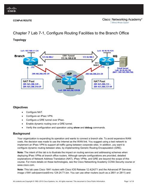
Topology<br />
Objectives<br />
• <strong>Configure</strong> NAT.<br />
• <strong>Configure</strong> an IPsec VPN.<br />
• <strong>Configure</strong> a GRE tunnel over IPsec.<br />
• Enable dynamic routing over a GRE tunnel.<br />
• Verify <strong>the</strong> configuration and operation using show and debug commands.<br />
Background<br />
Your organization is expanding its operation and wants <strong>to</strong> connect a branch site. To avoid expensive WAN<br />
costs, <strong>the</strong> decision was made <strong>to</strong> use <strong>the</strong> Internet as <strong>the</strong> WAN link. You suggest using a test network <strong>to</strong><br />
implement an IPsec VPN <strong>to</strong> support all traffic going between corporate sites. In addition, you want <strong>to</strong><br />
configure dynamic routing between sites, by implementing Generic <strong>Routing</strong> Encapsulation (GRE).<br />
Note: The intent of this lab is <strong>to</strong> illustrate <strong>the</strong> impact on routing services and addressing schemes when<br />
deploying IPsec VPNs at branch office routers. Although sample configurations are provided, detailed<br />
explanations of Network Address Translation (NAT), IPsec VPNs, and GRE are beyond <strong>the</strong> scope of this<br />
course. For more details on <strong>the</strong>se technologies, see <strong>the</strong> Cisco Networking Academy CCNA Security course or<br />
www.cisco.com.<br />
Note: This lab uses Cisco 1841 routers with Cisco IOS Release 12.4(24)T1 and <strong>the</strong> Advanced IP Services<br />
image c1841-advipservicesk9-mz.124-24.T1.bin. You can use o<strong>the</strong>r routers (such as a 2801 or 2811) and<br />
All contents are Copyright © 1992–2010 Cisco Systems, Inc. All rights reserved. This document is Cisco Public Information. Page 1 of 18
CCNPv6 ROUTE<br />
Cisco IOS Software versions if <strong>the</strong>y have comparable capabilities and features. Depending on <strong>the</strong> router and<br />
Cisco IOS Software version, <strong>the</strong> commands available and output produced might vary from what is shown in<br />
this lab.<br />
Required Resources<br />
• 3 routers (Cisco 1841 with Cisco IOS Release 12.4(24)T1 Advanced IP Services or comparable)<br />
• Serial and console cables<br />
Step 1: Prepare <strong>the</strong> routers and configure <strong>the</strong> router hostname and interface addresses.<br />
a. Cable <strong>the</strong> network as shown in <strong>the</strong> <strong>to</strong>pology diagram. Erase <strong>the</strong> startup configuration and reload each<br />
router <strong>to</strong> clear previous configurations. Using <strong>the</strong> addressing scheme in <strong>the</strong> diagram, apply <strong>the</strong> IP<br />
addresses <strong>to</strong> <strong>the</strong> interfaces on <strong>Branch</strong>, HQ, and ISP.<br />
You can copy and paste <strong>the</strong> following configurations in<strong>to</strong> your routers <strong>to</strong> begin.<br />
Note: Depending on <strong>the</strong> router model, interfaces might be numbered differently than those listed. You<br />
might need <strong>to</strong> alter <strong>the</strong> designations accordingly.<br />
<strong>Branch</strong> (R1)<br />
hostname <strong>Branch</strong><br />
!<br />
interface Loopback1<br />
description <strong>Branch</strong> LAN<br />
ip address 192.168.1.1 255.255.255.0<br />
!<br />
interface Serial0/0/1<br />
description Connection <strong>to</strong> ISP<br />
ip address 209.165.200.242 255.255.255.248<br />
bandwidth 64<br />
no shut<br />
!<br />
end<br />
HQ (R2)<br />
hostname HQ<br />
!<br />
interface Loopback1<br />
description Headquarters LAN<br />
ip address 10.10.10.1 255.255.255.0<br />
!<br />
interface Serial0/0/1<br />
description Connection <strong>to</strong> ISP<br />
ip address 209.165.200.226 255.255.255.248<br />
clock rate 64000<br />
bandwidth 64<br />
no shut<br />
!<br />
end<br />
ISP (R3)<br />
hostname ISP<br />
!<br />
interface Loopback1<br />
description Simulating <strong>the</strong> Internet<br />
ip address 209.165.202.129 255.255.255.240<br />
All contents are Copyright © 1992–2010 Cisco Systems, Inc. All rights reserved. This document is Cisco Public Information. Page 2 of 18
CCNPv6 ROUTE<br />
!<br />
interface Serial0/0/0<br />
description Connection <strong>to</strong> <strong>Branch</strong><br />
ip address 209.165.200.241 255.255.255.248<br />
clock rate 64000<br />
bandwidth 64<br />
no shut<br />
!<br />
interface Serial0/0/1<br />
description Connection <strong>to</strong> HQ<br />
ip address 209.165.200.225 255.255.255.248<br />
bandwidth 64<br />
no shut<br />
ip route 209.165.200.232 255.255.255.248 Serial0/0/1<br />
ip route 209.165.200.248 255.255.255.248 Serial0/0/0<br />
!<br />
end<br />
b. Verify your configuration by using <strong>the</strong> show ip interface brief command. The output from <strong>the</strong> <strong>Branch</strong><br />
router is shown here as an example.<br />
<strong>Branch</strong># show ip interface brief<br />
Interface IP-Address OK? Method Status Pro<strong>to</strong>col<br />
FastE<strong>the</strong>rnet0/0 unassigned YES unset administratively down down<br />
FastE<strong>the</strong>rnet0/1 unassigned YES unset administratively down down<br />
Serial0/0/0 unassigned YES unset administratively down down<br />
Serial0/0/1 209.165.200.242 YES manual up up<br />
Loopback1 192.168.1.1 YES manual up up<br />
c. From <strong>the</strong> <strong>Branch</strong> LAN interface, use an extended ping <strong>to</strong> verify connectivity <strong>to</strong> <strong>the</strong> directly connected<br />
interface of <strong>the</strong> ISP, <strong>the</strong> ISPs loopback interface, and <strong>the</strong> HQ Internet interface. Run <strong>the</strong> following Tcl<br />
script on <strong>the</strong> <strong>Branch</strong> router <strong>to</strong> verify connectivity.<br />
<strong>Branch</strong># tclsh<br />
foreach address {<br />
209.165.200.241<br />
209.165.202.129<br />
209.165.200.226<br />
} { ping $address}<br />
Type escape sequence <strong>to</strong> abort.<br />
Sending 5, 100-byte ICMP Echos <strong>to</strong> 209.165.200.241, timeout is 2 seconds:<br />
!!!!!<br />
Success rate is 100 percent (5/5), round-trip min/avg/max = 28/28/32 ms<br />
Type escape sequence <strong>to</strong> abort.<br />
Sending 5, 100-byte ICMP Echos <strong>to</strong> 209.165.202.129, timeout is 2 seconds:<br />
.....<br />
Success rate is 0 percent (0/5)<br />
Type escape sequence <strong>to</strong> abort.<br />
Sending 5, 100-byte ICMP Echos <strong>to</strong> 209.165.200.226, timeout is 2 seconds:<br />
.....<br />
Success rate is 0 percent (0/5)<br />
<strong>Branch</strong>(tcl)#<br />
All contents are Copyright © 1992–2010 Cisco Systems, Inc. All rights reserved. This document is Cisco Public Information. Page 3 of 18
CCNPv6 ROUTE<br />
Why do <strong>the</strong> pings <strong>to</strong> <strong>the</strong> ISPs loopback and HQ router address fail?<br />
_______________________________________________________________________________<br />
_______________________________________________________________________________<br />
d. <strong>Configure</strong> a default static route <strong>to</strong> ISP on <strong>the</strong> <strong>Branch</strong> and HQ routers.<br />
You can copy and paste <strong>the</strong> following configurations in<strong>to</strong> your routers.<br />
<strong>Branch</strong>(config)# ip route 0.0.0.0 0.0.0.0 209.165.200.241<br />
HQ(config)# ip route 0.0.0.0 0.0.0.0 209.165.200.225<br />
e. From <strong>the</strong> <strong>Branch</strong> router, run <strong>the</strong> following Tcl script on <strong>the</strong> <strong>Branch</strong> router <strong>to</strong> verify connectivity.<br />
<strong>Branch</strong># tclsh<br />
foreach address {<br />
209.165.200.241<br />
209.165.202.129<br />
209.165.200.226<br />
+>} { ping $address}<br />
Type escape sequence <strong>to</strong> abort.<br />
Sending 5, 100-byte ICMP Echos <strong>to</strong> 209.165.200.241, timeout is 2 seconds:<br />
!!!!!<br />
Success rate is 100 percent (5/5), round-trip min/avg/max = 28/28/32 ms<br />
Type escape sequence <strong>to</strong> abort.<br />
Sending 5, 100-byte ICMP Echos <strong>to</strong> 209.165.202.129, timeout is 2 seconds:<br />
!!!!!<br />
Success rate is 100 percent (5/5), round-trip min/avg/max = 28/28/32 ms<br />
Type escape sequence <strong>to</strong> abort.<br />
Sending 5, 100-byte ICMP Echos <strong>to</strong> 209.165.200.226, timeout is 2 seconds:<br />
!!!!!<br />
Success rate is 100 percent (5/5), round-trip min/avg/max = 56/56/56 ms<br />
<strong>Branch</strong>(tcl)#<br />
Are <strong>the</strong> pings now successful?<br />
_______________________________________________________________________________<br />
_______________________________________________________________________________<br />
f. Connectivity from <strong>the</strong> <strong>Branch</strong> router <strong>to</strong> external addresses has been established. But could a <strong>Branch</strong> LAN<br />
user successfully reach those external addresses? To verify, initiate pings sourced from <strong>the</strong> <strong>Branch</strong> LAN<br />
interface <strong>to</strong> <strong>the</strong> ISP interface, <strong>the</strong> ISPs loopback interface, and <strong>the</strong> HQ Internet interface. Run <strong>the</strong><br />
following Tcl script on <strong>the</strong> <strong>Branch</strong> router <strong>to</strong> verify connectivity.<br />
<strong>Branch</strong># tclsh<br />
foreach address {<br />
209.165.200.241<br />
209.165.202.129<br />
209.165.200.226<br />
} { ping $address source 192.168.1.1}<br />
Type escape sequence <strong>to</strong> abort.<br />
Sending 5, 100-byte ICMP Echos <strong>to</strong> 209.165.200.241, timeout is 2 seconds:<br />
Packet sent with a source address of 192.168.1.1<br />
.....<br />
All contents are Copyright © 1992–2010 Cisco Systems, Inc. All rights reserved. This document is Cisco Public Information. Page 4 of 18
CCNPv6 ROUTE<br />
Success rate is 0 percent (0/5)<br />
Type escape sequence <strong>to</strong> abort.<br />
Sending 5, 100-byte ICMP Echos <strong>to</strong> 209.165.202.129, timeout is 2 seconds:<br />
Packet sent with a source address of 192.168.1.1<br />
.....<br />
Success rate is 0 percent (0/5)<br />
Type escape sequence <strong>to</strong> abort.<br />
Sending 5, 100-byte ICMP Echos <strong>to</strong> 209.165.200.226, timeout is 2 seconds:<br />
Packet sent with a source address of 192.168.1.1<br />
.....<br />
Success rate is 0 percent (0/5)<br />
<strong>Branch</strong>(tcl)#<br />
Note: You can also specify <strong>the</strong> router interface designa<strong>to</strong>r (for example, S0/0/0, Fa0/0, or Lo1) as <strong>the</strong><br />
source for <strong>the</strong> extended ping, as follows:<br />
<strong>Branch</strong># ping 209.165.200.226 source Lo1<br />
Why are <strong>the</strong> pings unsuccessful?<br />
_______________________________________________________________________________<br />
_______________________________________________________________________________<br />
The ISP cannot route back <strong>to</strong> <strong>the</strong> internal private address of <strong>the</strong> <strong>Branch</strong> LAN.<br />
Step 2: <strong>Configure</strong> NAT on <strong>the</strong> <strong>Branch</strong> and HQ routers.<br />
The internal LAN private IP addresses will be translated <strong>to</strong> global public IP addresses using NAT. The ISP<br />
has provided <strong>the</strong> HQ and <strong>Branch</strong> sites with <strong>the</strong> following pools of public addresses:<br />
• HQ: 209.165.200.233 – 209.165.200.238 (209.165.200.232/29)<br />
• <strong>Branch</strong>: 209.165.200.249 – 209.165.200.254 (209.165.200.248/29)<br />
The HQ site also has an email server that must be accessible <strong>to</strong> mobile users and <strong>Branch</strong> office users.<br />
Therefore, static NAT must also be configured <strong>to</strong> use a public address <strong>to</strong> reach <strong>the</strong> email server.<br />
a. The NAT pool identifies public IP addresses, while <strong>the</strong> NAT ACL identifies which inside hosts can use<br />
<strong>the</strong>se public IP addresses. For <strong>the</strong> <strong>Branch</strong> router, this means that <strong>the</strong> NAT ACL must identify <strong>the</strong><br />
192.168.1.0 LAN, and <strong>the</strong> NAT pool must identify addresses 209.165.200.248 /29. The LAN interface<br />
must be identified as an inside NAT interface, and <strong>the</strong> Internet interface must be identified as an outside<br />
NAT interface.<br />
Note: The NAT ACL must not translate <strong>the</strong> <strong>Branch</strong> LAN addresses if <strong>the</strong>y are destined <strong>to</strong> <strong>the</strong> corporate<br />
HQ LAN. Therefore, <strong>the</strong> NAT ACL denies <strong>the</strong> <strong>Branch</strong> LAN public addresses from being translated when<br />
attempting <strong>to</strong> connect <strong>to</strong> <strong>the</strong> HQ LANs. This will be required when <strong>the</strong> IPsec VPN is configured.<br />
You can copy and paste <strong>the</strong> following configuration in<strong>to</strong> <strong>the</strong> <strong>Branch</strong> router.<br />
<strong>Branch</strong> Router<br />
ip access-list extended BRANCH-NAT-ACL<br />
remark Do not translate Local LAN <strong>to</strong> HQ LAN addresses<br />
deny ip 192.168.1.0 0.0.0.255 10.10.0.0 0.0.255.255<br />
remark Translate Local LAN <strong>to</strong> all o<strong>the</strong>r Internet destinations<br />
permit ip 192.168.1.0 0.0.0.255 any<br />
exit<br />
!<br />
ip nat pool BRANCH-NAT-POOL 209.165.200.249 209.165.200.254 prefix-length 29<br />
!<br />
All contents are Copyright © 1992–2010 Cisco Systems, Inc. All rights reserved. This document is Cisco Public Information. Page 5 of 18
CCNPv6 ROUTE<br />
ip nat inside source list BRANCH-NAT-ACL pool BRANCH-NAT-POOL<br />
!<br />
interface Loopback 1<br />
ip nat inside<br />
exit<br />
!<br />
interface Serial0/0/1<br />
ip nat outside<br />
end<br />
b. On <strong>the</strong> HQ router, <strong>the</strong> NAT ACL must identify <strong>the</strong> 10.10.10.0 and <strong>the</strong> 10.10.20.0 LANs. The NAT pool<br />
must identify addresses 209.165.200.232 /29. The LAN interface must be identified as an inside NAT<br />
interface, and <strong>the</strong> Internet interface must be identified as an outside NAT interface.<br />
The email server with private IP address 10.10.20.238 will be statically assigned <strong>the</strong> last public IP<br />
address from <strong>the</strong> NAT pool, 209.165.200.238. Interface loopback 0 on HQ simulates this server.<br />
Note: Again <strong>the</strong> NAT ACL denies <strong>the</strong> HQ LAN public addresses from being translated when attempting <strong>to</strong><br />
connect <strong>to</strong> <strong>the</strong> <strong>Branch</strong> LAN which will be required when <strong>the</strong> IPsec VPN is configured.<br />
You can copy and paste <strong>the</strong> following configuration in<strong>to</strong> <strong>the</strong> HQ router.<br />
HQ Router<br />
interface Loopback 0<br />
description HQ email server address<br />
ip add 10.10.20.238 255.255.255.0<br />
!<br />
ip nat pool HQ-NAT-POOL 209.165.200.233 209.165.200.237 prefix-length 29<br />
ip nat inside source list HQ-NAT-ACL pool HQ-NAT-POOL<br />
ip nat inside source static 10.10.20.238 209.165.200.238<br />
!<br />
ip access-list extended HQ-NAT-ACL<br />
remark Do not translate HQ LAN <strong>to</strong> <strong>Branch</strong> LAN addresses<br />
deny ip 10.10.0.0 0.0.255.255 192.168.1.0 0.0.0.255<br />
remark Translate Local LAN <strong>to</strong> all o<strong>the</strong>r Internet destinations<br />
permit ip 10.10.0.0 0.0.255.255 any<br />
exit<br />
!<br />
interface Loopback 0<br />
ip nat inside<br />
!<br />
interface Loopback 1<br />
ip nat inside<br />
!<br />
interface Serial0/0/1<br />
ip nat outside<br />
end<br />
c. Verify <strong>the</strong> NAT configuration by using <strong>the</strong> show ip nat statistics and show ip nat translations<br />
commands.<br />
<strong>Branch</strong># show ip nat statistics<br />
Total active translations: 0 (0 static, 0 dynamic; 0 extended)<br />
Peak translations: 0, occurred 00:018:28 ago<br />
Outside interfaces:<br />
Serial0/0/1<br />
Inside interfaces:<br />
Loopback1<br />
Hits: 0 Misses: 0<br />
All contents are Copyright © 1992–2010 Cisco Systems, Inc. All rights reserved. This document is Cisco Public Information. Page 6 of 18
CCNPv6 ROUTE<br />
CEF Translated packets: 0, CEF Punted packets: 0<br />
Expired translations: 0<br />
Dynamic mappings:<br />
-- Inside Source<br />
[Id: 1] access-list BRANCH-NAT-ACL pool BRANCH-NAT-POOL refcount 0<br />
pool BRANCH-NAT-POOL: netmask 255.255.255.248<br />
start 209.165.200.249 end 209.165.200.254<br />
type generic, <strong>to</strong>tal addresses 6, allocated 0 (0%), misses 0<br />
Appl doors: 0<br />
Normal doors: 0<br />
Queued Packets: 0<br />
As shown above, <strong>the</strong> pool has been configured and <strong>the</strong> interfaces assigned. The output of <strong>the</strong> show ip<br />
nat translations command confirms that <strong>the</strong>re are currently no active NAT translations:<br />
<strong>Branch</strong># show ip nat translations<br />
<strong>Branch</strong>#<br />
d. Initiate NAT traffic by pinging from <strong>the</strong> <strong>Branch</strong> LAN <strong>to</strong> <strong>the</strong> ISP interface, ISP’s loopback, <strong>the</strong> HQ Internet<br />
interface, and this time also include <strong>the</strong> HQ public email server address. Run <strong>the</strong> following Tcl script on<br />
<strong>the</strong> <strong>Branch</strong> router <strong>to</strong> verify connectivity.<br />
<strong>Branch</strong># tclsh<br />
foreach address {<br />
209.165.200.241<br />
209.165.202.129<br />
209.165.200.226<br />
209.165.200.238<br />
} { ping $address source 192.168.1.1}<br />
Type escape sequence <strong>to</strong> abort.<br />
Sending 5, 100-byte ICMP Echos <strong>to</strong> 209.165.200.241, timeout is 2 seconds:<br />
Packet sent with a source address of 192.168.1.1<br />
!!!!!<br />
Success rate is 100 percent (5/5), round-trip min/avg/max = 28/29/32 ms<br />
Type escape sequence <strong>to</strong> abort.<br />
Sending 5, 100-byte ICMP Echos <strong>to</strong> 209.165.202.129, timeout is 2 seconds:<br />
Packet sent with a source address of 192.168.1.1<br />
!!!!!<br />
Success rate is 100 percent (5/5), round-trip min/avg/max = 28/28/32 ms<br />
Type escape sequence <strong>to</strong> abort.<br />
Sending 5, 100-byte ICMP Echos <strong>to</strong> 209.165.200.226, timeout is 2 seconds:<br />
Packet sent with a source address of 192.168.1.1<br />
!!!!!<br />
Success rate is 100 percent (5/5), round-trip min/avg/max = 56/56/60 ms<br />
Type escape sequence <strong>to</strong> abort.<br />
Sending 5, 100-byte ICMP Echos <strong>to</strong> 209.165.200.238, timeout is 2 seconds:<br />
Packet sent with a source address of 192.168.1.1<br />
!!!!!<br />
Success rate is 100 percent (5/5), round-trip min/avg/max = 56/57/60 ms<br />
<strong>Branch</strong>(tcl)#<br />
All pings should be successful.<br />
e. Verify that NAT is occurring by using <strong>the</strong> show ip nat statistics and show ip nat translations<br />
commands.<br />
All contents are Copyright © 1992–2010 Cisco Systems, Inc. All rights reserved. This document is Cisco Public Information. Page 7 of 18
CCNPv6 ROUTE<br />
<strong>Branch</strong># show ip nat statistics<br />
Total active translations: 5 (0 static, 5 dynamic; 4 extended)<br />
Peak translations: 5, occurred 00:00:12 ago<br />
Outside interfaces:<br />
Serial0/0/1<br />
Inside interfaces:<br />
Loopback1<br />
Hits: 40 Misses: 0<br />
CEF Translated packets: 20, CEF Punted packets: 0<br />
Expired translations: 0<br />
Dynamic mappings:<br />
-- Inside Source<br />
[Id: 1] access-list BRANCH-NAT-ACL pool BRANCH-NAT-POOL refcount 5<br />
pool BRANCH-NAT-POOL: netmask 255.255.255.248<br />
start 209.165.200.249 end 209.165.200.254<br />
type generic, <strong>to</strong>tal addresses 6, allocated 1 (16%), misses 0<br />
Appl doors: 0<br />
Normal doors: 0<br />
Queued Packets: 0<br />
<strong>Branch</strong>#<br />
<strong>Branch</strong># show ip nat translations<br />
Pro Inside global Inside local Outside local Outside global<br />
icmp 209.165.200.249:9 192.168.1.1:9 209.165.200.241:9 209.165.200.241:9<br />
icmp 209.165.200.249:10 192.168.1.1:10 209.165.202.129:10 209.165.202.129:10<br />
icmp 209.165.200.249:11 192.168.1.1:11 209.165.200.226:11 209.165.200.226:11<br />
icmp 209.165.200.249:12 192.168.1.1:12 209.165.200.238:12 209.165.200.238:12<br />
--- 209.165.200.249 192.168.1.1 --- ---<br />
<strong>Branch</strong>#<br />
Notice that translations are occurring. The output lists <strong>the</strong> details of <strong>the</strong> NAT translations sourced by <strong>the</strong><br />
192.168.1.1 <strong>Branch</strong> LAN IP address, which was translated <strong>to</strong> public IP address 209.165.200.249.<br />
f. Now clear <strong>the</strong> NAT translations, verify connectivity from <strong>the</strong> <strong>Branch</strong> LAN <strong>to</strong> <strong>the</strong> HQ LAN interface and<br />
<strong>the</strong>n display <strong>the</strong> NAT translations.<br />
<strong>Branch</strong># clear ip nat translation *<br />
<strong>Branch</strong>#<br />
<strong>Branch</strong># ping 10.10.10.1 source 192.168.1.1<br />
Type escape sequence <strong>to</strong> abort.<br />
Sending 5, 100-byte ICMP Echos <strong>to</strong> 10.10.10.1, timeout is 2 seconds:<br />
Packet sent with a source address of 192.168.1.1<br />
.....<br />
Success rate is 0 percent (0/5)<br />
<strong>Branch</strong>#<br />
<strong>Branch</strong># show ip nat translations<br />
<strong>Branch</strong>#<br />
As expected, <strong>Branch</strong> LAN traffic going <strong>to</strong> <strong>the</strong> HQ LAN is not translated by NAT. The ISP cannot route <strong>the</strong><br />
pings <strong>to</strong> <strong>the</strong> private address on HQ and, <strong>the</strong>refore, <strong>the</strong> pings fail.<br />
NAT works as expected. Traffic source from <strong>the</strong> <strong>Branch</strong> LAN going <strong>to</strong> Internet destinations is translated<br />
while traffic sourced from <strong>the</strong> <strong>Branch</strong> LAN <strong>to</strong> <strong>the</strong> HQ LAN is not translated. However, this traffic should be<br />
protected when traversing <strong>the</strong> public Internet. To solve this problem, an IPsec VPN will be configured<br />
next.<br />
All contents are Copyright © 1992–2010 Cisco Systems, Inc. All rights reserved. This document is Cisco Public Information. Page 8 of 18
CCNPv6 ROUTE<br />
Step 3: Implement an IPsec VPN between <strong>the</strong> <strong>Branch</strong> and HQ sites.<br />
An IPsec VPN can secure and protect all unicast IP traffic within it. IPsec cannot forward multicast or<br />
broadcast traffic, which means it cannot support interior gateway pro<strong>to</strong>cols such as EIGRP and OSPF.<br />
For this lab, assume that <strong>the</strong> network security team has provided a basic IPsec VPN configuration with which<br />
<strong>to</strong> test your network design. As shown in <strong>the</strong> following figure, it consists of several configuration components:<br />
• The ISAKMP policy identifies <strong>the</strong> specifics for <strong>the</strong> initial key and secure parameters exchange.<br />
• The IPsec details define how <strong>the</strong> IP packet is encapsulated.<br />
• The VPN tunnel information is identified in a named cryp<strong>to</strong> map which combines <strong>the</strong> ISAKMP<br />
policies, IPsec packet detail, <strong>the</strong> peer address, and <strong>the</strong> cryp<strong>to</strong> ACL.<br />
• The cryp<strong>to</strong> ACL identifies traffic that will trigger <strong>the</strong> tunnel <strong>to</strong> activate. This component must<br />
sometimes be tuned when implemented along with o<strong>the</strong>r services such as NAT and GRE.<br />
• The cryp<strong>to</strong> map is <strong>the</strong>n applied <strong>to</strong> <strong>the</strong> tunnel interface.<br />
Note: How <strong>to</strong> configure an IPsec VPN is beyond <strong>the</strong> scope of this lab. For more information on cryp<strong>to</strong>graphy,<br />
IPsec VPNs, and GRE, see <strong>the</strong> Cisco Networking Academy CCNA Security courses or www.cisco.com.<br />
a. Copy and paste <strong>the</strong> following configurations on <strong>the</strong> routers.<br />
<strong>Branch</strong> Router<br />
cryp<strong>to</strong> isakmp policy 1<br />
encryption aes<br />
au<strong>the</strong>ntication pre-share<br />
group 2<br />
cryp<strong>to</strong> isakmp key cisco123 address 209.165.200.226<br />
!<br />
cryp<strong>to</strong> ipsec transform-set HQ-VPN esp-3des esp-sha-hmac<br />
All contents are Copyright © 1992–2010 Cisco Systems, Inc. All rights reserved. This document is Cisco Public Information. Page 9 of 18
CCNPv6 ROUTE<br />
!<br />
cryp<strong>to</strong> map HQ-MAP 10 ipsec-isakmp<br />
set peer 209.165.200.226<br />
set transform-set HQ-VPN<br />
match address HQ-VPN-ACL<br />
!<br />
ip access-list extended HQ-VPN-ACL<br />
remark <strong>Branch</strong> <strong>to</strong> HQ traffic <strong>to</strong> trigger VPN<br />
permit ip 192.168.1.0 0.0.0.255 10.10.0.0 0.0.255.255<br />
!<br />
interface Serial0/0/1<br />
cryp<strong>to</strong> map HQ-MAP<br />
end<br />
HQ Router<br />
cryp<strong>to</strong> isakmp policy 1<br />
encryption aes<br />
au<strong>the</strong>ntication pre-share<br />
group 2<br />
cryp<strong>to</strong> isakmp key cisco123 address 209.165.200.242<br />
!<br />
cryp<strong>to</strong> ipsec transform-set <strong>Branch</strong>-VPN esp-3des esp-sha-hmac<br />
!<br />
cryp<strong>to</strong> map <strong>Branch</strong>-MAP 10 ipsec-isakmp<br />
set peer 209.165.200.242<br />
set transform-set <strong>Branch</strong>-VPN<br />
match address <strong>Branch</strong>-VPN-ACL<br />
!<br />
ip access-list extended <strong>Branch</strong>-VPN-ACL<br />
remark HQ <strong>to</strong> <strong>Branch</strong> traffic <strong>to</strong> trigger VPN<br />
permit ip 10.10.0.0 0.0.255.255 192.168.1.0 0.0.0.255<br />
!<br />
interface Serial0/0/1<br />
cryp<strong>to</strong> map <strong>Branch</strong>-MAP<br />
end<br />
Notice that <strong>the</strong> cryp<strong>to</strong> ACLs are referring <strong>to</strong> <strong>the</strong> public IP addresses and not <strong>the</strong> private IP addresses.<br />
This is because <strong>the</strong> cryp<strong>to</strong> map applies <strong>to</strong> <strong>the</strong> traffic after <strong>the</strong> NAT has already taken place. Ano<strong>the</strong>r<br />
alternative approach would be <strong>to</strong> exempt site-<strong>to</strong>-site traffic from <strong>the</strong> NAT translation pool and have <strong>the</strong><br />
cryp<strong>to</strong> ACLs trigger based on private addresses instead of <strong>the</strong> public address pool.<br />
b. Use <strong>the</strong> show cryp<strong>to</strong> session detail command on <strong>the</strong> <strong>Branch</strong> router <strong>to</strong> verify <strong>the</strong> overall configuration of<br />
<strong>the</strong> IPsec VPN.<br />
<strong>Branch</strong># show cryp<strong>to</strong> session detail<br />
Cryp<strong>to</strong> session current status<br />
Code: C - IKE Configuration mode, D - Dead Peer Detection<br />
K - Keepalives, N - NAT-traversal, T - cTCP encapsulation<br />
X - IKE Extended Au<strong>the</strong>ntication, F - IKE Fragmentation<br />
Interface: Serial0/0/1<br />
Session status: DOWN<br />
Peer: 209.165.200.226 port 500 fvrf: (none) ivrf: (none)<br />
Desc: (none)<br />
All contents are Copyright © 1992–2010 Cisco Systems, Inc. All rights reserved. This document is Cisco Public Information. Page 10 of 18
CCNPv6 ROUTE<br />
Phase1_id: (none)<br />
IPSEC FLOW: permit ip 192.168.1.0/255.255.255.0 10.10.0.0/255.255.0.0<br />
Active SAs: 0, origin: cryp<strong>to</strong> map<br />
Inbound: #pkts dec'ed 0 drop 0 life (KB/Sec) 0/0<br />
Outbound: #pkts enc'ed 0 drop 0 life (KB/Sec) 0/0<br />
<strong>Branch</strong>#<br />
The VPN tunnel is currently down because <strong>the</strong> traffic identified in <strong>the</strong> IPSEC FLOW has not yet been<br />
processed.<br />
c. To test <strong>the</strong> VPN link, use an extended ping from <strong>the</strong> <strong>Branch</strong> LAN interface <strong>to</strong> <strong>the</strong> HQ LAN interface.<br />
<strong>Branch</strong># ping 10.10.10.1 source 192.168.1.1<br />
Type escape sequence <strong>to</strong> abort.<br />
Sending 5, 100-byte ICMP Echos <strong>to</strong> 10.10.10.1, timeout is 2 seconds:<br />
Packet sent with a source address of 192.168.1.1<br />
.!!!!<br />
Success rate is 80 percent (4/5), round-trip min/avg/max = 84/86/88 ms<br />
<strong>Branch</strong>#<br />
This time 80% of <strong>the</strong> pings were successful. This is typical because <strong>the</strong> VPN tunnel requires a few<br />
seconds <strong>to</strong> negotiate <strong>the</strong> security parameters specified in <strong>the</strong> cryp<strong>to</strong> map.<br />
d. Now display <strong>the</strong> VPN tunnel details again.<br />
<strong>Branch</strong># show cryp<strong>to</strong> session detail<br />
Cryp<strong>to</strong> session current status<br />
Code: C - IKE Configuration mode, D - Dead Peer Detection<br />
K - Keepalives, N - NAT-traversal, T - cTCP encapsulation<br />
X - IKE Extended Au<strong>the</strong>ntication, F - IKE Fragmentation<br />
Interface: Serial0/0/1<br />
Uptime: 00:00:10<br />
Session status: UP-ACTIVE<br />
Peer: 209.165.200.226 port 500 fvrf: (none) ivrf: (none)<br />
Phase1_id: 209.165.200.226<br />
Desc: (none)<br />
IKE SA: local 209.165.200.242/500 remote 209.165.200.226/500 Active<br />
Capabilities:(none) connid:1001 lifetime:23:59:49<br />
IPSEC FLOW: permit ip 192.168.1.0/255.255.255.0 10.10.0.0/255.255.0.0<br />
Active SAs: 2, origin: cryp<strong>to</strong> map<br />
Inbound: #pkts dec'ed 4 drop 0 life (KB/Sec) 4430126/3589<br />
Outbound: #pkts enc'ed 4 drop 1 life (KB/Sec) 4430126/3589<br />
<strong>Branch</strong>#<br />
The VPN tunnel did become active as indicated by <strong>the</strong> UP-ACTIVE session status. Also notice that it was<br />
<strong>the</strong> permit statement is referring <strong>to</strong> <strong>the</strong> private addresses defined in <strong>the</strong> cryp<strong>to</strong> ACL and that it encrypted<br />
and decrypted four packets, with only one packet dropped due <strong>to</strong> <strong>the</strong> IPsec negotiation.<br />
e. Before proceeding, manually disable <strong>the</strong> IPsec VPN tunnel using <strong>the</strong> clear cryp<strong>to</strong> isakmp and clear<br />
cryp<strong>to</strong> sa commands on <strong>the</strong> <strong>Branch</strong> router.<br />
All contents are Copyright © 1992–2010 Cisco Systems, Inc. All rights reserved. This document is Cisco Public Information. Page 11 of 18
CCNPv6 ROUTE<br />
<strong>Branch</strong># clear cryp<strong>to</strong> isakmp<br />
<strong>Branch</strong># clear cryp<strong>to</strong> sa<br />
<strong>Branch</strong>#<br />
You now have encrypted connectivity from <strong>the</strong> <strong>Branch</strong> LAN <strong>to</strong> HQ LAN. <strong>the</strong> problem with an IPsec VPN is<br />
that it does not allow dynamic routing pro<strong>to</strong>cols <strong>to</strong> operate over it. However, GRE can help solve this<br />
problem.<br />
Step 4: Implement GRE over IPsec.<br />
A GRE tunnel over IPsec can be implemented between <strong>the</strong> <strong>Branch</strong> and HQ sites. The tunnel will protect all<br />
corporate LAN traffic. As a bonus, GRE can forward multicast and broadcast traffic, so dynamic routing can<br />
also be enabled.<br />
a. <strong>Configure</strong> <strong>the</strong> tunnel interfaces on <strong>the</strong> <strong>Branch</strong> router and HQ routers with GRE encapsulation. Copy and<br />
paste <strong>the</strong> following configurations on <strong>the</strong> routers.<br />
<strong>Branch</strong> Router<br />
interface Tunnel0<br />
ip address 172.16.100.2 255.255.255.252<br />
tunnel source 209.165.200.242<br />
tunnel destination 209.165.200.226<br />
HQ Router<br />
interface Tunnel0<br />
ip address 172.16.100.1 255.255.255.252<br />
tunnel source 209.165.200.226<br />
tunnel destination 209.165.200.242<br />
You should notice <strong>the</strong> state of <strong>the</strong> tunnel interfaces <strong>to</strong> change <strong>to</strong> up on both routers.<br />
%LINEPROTO-5-UPDOWN: Line pro<strong>to</strong>col on Interface Tunnel0, changed state <strong>to</strong> up<br />
b. Verify that <strong>the</strong> tunnel interface is up and running using <strong>the</strong> show interface tunnel 0 command.<br />
<strong>Branch</strong># show interfaces tunnel 0<br />
Tunnel0 is up, line pro<strong>to</strong>col is up<br />
Hardware is Tunnel<br />
Internet address is 172.16.100.2/30<br />
MTU 17916 bytes, BW 100 Kbit/sec, DLY 50000 usec,<br />
reliability 255/255, txload 1/255, rxload 1/255<br />
Encapsulation TUNNEL, loopback not set<br />
Keepalive not set<br />
Tunnel source 209.165.200.242, destination 209.165.200.226<br />
Tunnel pro<strong>to</strong>col/transport GRE/IP<br />
Key disabled, sequencing disabled<br />
Checksumming of packets disabled<br />
Tunnel TTL 255<br />
Fast tunneling enabled<br />
Tunnel transport MTU 1476 bytes<br />
Tunnel transmit bandwidth 8000 (kbps)<br />
Tunnel receive bandwidth 8000 (kbps)<br />
Last input never, output never, output hang never<br />
Last clearing of "show interface" counters never<br />
Input queue: 0/75/0/0 (size/max/drops/flushes); Total output drops: 0<br />
Queueing strategy: fifo<br />
Output queue: 0/0 (size/max)<br />
5 minute input rate 0 bits/sec, 0 packets/sec<br />
All contents are Copyright © 1992–2010 Cisco Systems, Inc. All rights reserved. This document is Cisco Public Information. Page 12 of 18
CCNPv6 ROUTE<br />
5 minute output rate 0 bits/sec, 0 packets/sec<br />
0 packets input, 0 bytes, 0 no buffer<br />
Received 0 broadcasts, 0 runts, 0 giants, 0 throttles<br />
0 input errors, 0 CRC, 0 frame, 0 overrun, 0 ignored, 0 abort<br />
0 packets output, 0 bytes, 0 underruns<br />
0 output errors, 0 collisions, 0 interface resets<br />
0 unknown pro<strong>to</strong>col drops<br />
0 output buffer failures, 0 output buffers swapped out<br />
<strong>Branch</strong>#<br />
The tunnel interface is up. Also notice that <strong>the</strong> encapsulation and tunnel transport pro<strong>to</strong>col is GRE/IP.<br />
c. Verify connectivity across <strong>the</strong> tunnel by pinging <strong>the</strong> tunnel destination on <strong>the</strong> HQ router. The pings should<br />
be successful.<br />
<strong>Branch</strong># ping 172.16.100.1<br />
Type escape sequence <strong>to</strong> abort.<br />
Sending 5, 100-byte ICMP Echos <strong>to</strong> 172.16.100.1, timeout is 2 seconds:<br />
!!!!!<br />
Success rate is 100 percent (5/5), round-trip min/avg/max = 68/70/72 ms<br />
d. The pings successfully reach <strong>the</strong> o<strong>the</strong>r side of <strong>the</strong> tunnel. But is <strong>the</strong> traffic being encrypted? Display <strong>the</strong><br />
IPsec VPN specifics.<br />
<strong>Branch</strong># show cryp<strong>to</strong> session detail<br />
Cryp<strong>to</strong> session current status<br />
Code: C - IKE Configuration mode, D - Dead Peer Detection<br />
K - Keepalives, N - NAT-traversal, T - cTCP encapsulation<br />
X - IKE Extended Au<strong>the</strong>ntication, F - IKE Fragmentation<br />
Interface: Serial0/0/1<br />
Session status: DOWN-NEGOTIATING<br />
Peer: 209.165.200.226 port 500 fvrf: (none) ivrf: (none)<br />
Desc: (none)<br />
Phase1_id: (none)<br />
IKE SA: local 209.165.200.242/500 remote 209.165.200.226/500 Inactive<br />
Capabilities:(none) connid:1001 lifetime:0<br />
IPSEC FLOW: permit ip 192.168.1.0/255.255.255.0 10.10.0.0/255.255.0.0<br />
Active SAs: 0, origin: cryp<strong>to</strong> map<br />
Inbound: #pkts dec'ed 0 drop 0 life (KB/Sec) 0/0<br />
Outbound: #pkts enc'ed 0 drop 0 life (KB/Sec) 0/0<br />
<strong>Branch</strong>#<br />
The IPsec VPN is down because <strong>the</strong> tunnel traffic has not been identified in <strong>the</strong> cryp<strong>to</strong> ACL.<br />
e. To solve this problem, replace <strong>the</strong> cryp<strong>to</strong> ACL <strong>to</strong> make GRE traffic interesting on <strong>the</strong> <strong>Branch</strong> and HQ<br />
routers. Copy and paste <strong>the</strong> following configurations on <strong>the</strong> routers.<br />
<strong>Branch</strong> Router<br />
no ip access-list extended HQ-VPN-ACL<br />
ip access-list extended HQ-VPN-ACL<br />
remark HQ <strong>to</strong> <strong>Branch</strong> GRE traffic <strong>to</strong> trigger VPN<br />
permit gre host 209.165.200.242 host 209.165.200.226<br />
All contents are Copyright © 1992–2010 Cisco Systems, Inc. All rights reserved. This document is Cisco Public Information. Page 13 of 18
CCNPv6 ROUTE<br />
HQ Router<br />
no ip access-list extended <strong>Branch</strong>-VPN-ACL<br />
ip access-list extended <strong>Branch</strong>-VPN-ACL<br />
remark <strong>Branch</strong> <strong>to</strong> HQ GRE traffic <strong>to</strong> trigger VPN<br />
permit gre host 209.165.200.226 host 209.165.200.242<br />
f. Test <strong>the</strong> link again. Notice <strong>the</strong> pings are 80% successful again.<br />
<strong>Branch</strong># ping 172.16.100.1<br />
Type escape sequence <strong>to</strong> abort.<br />
Sending 5, 100-byte ICMP Echos <strong>to</strong> 172.16.100.1, timeout is 2 seconds:<br />
.!!!!<br />
Success rate is 80 percent (4/5), round-trip min/avg/max = 96/98/100 ms<br />
g. Display <strong>the</strong> IPsec session details.<br />
<strong>Branch</strong># show cryp<strong>to</strong> session detail<br />
Cryp<strong>to</strong> session current status<br />
Code: C - IKE Configuration mode, D - Dead Peer Detection<br />
K - Keepalives, N - NAT-traversal, T - cTCP encapsulation<br />
X - IKE Extended Au<strong>the</strong>ntication, F - IKE Fragmentation<br />
Interface: Serial0/0/1<br />
Uptime: 00:00:05<br />
Session status: UP-ACTIVE<br />
Peer: 209.165.200.226 port 500 fvrf: (none) ivrf: (none)<br />
Phase1_id: 209.165.200.226<br />
Desc: (none)<br />
IKE SA: local 209.165.200.242/500 remote 209.165.200.226/500 Active<br />
Capabilities:(none) connid:1003 lifetime:23:59:54<br />
IPSEC FLOW: permit 47 host 209.165.200.242 host 209.165.200.226<br />
Active SAs: 2, origin: cryp<strong>to</strong> map<br />
Inbound: #pkts dec'ed 4 drop 0 life (KB/Sec) 4422647/3594<br />
Outbound: #pkts enc'ed 4 drop 1 life (KB/Sec) 4422647/3594<br />
The IPsec tunnel is now up and active. The “permit 47” identifies GRE traffic as interesting. The value 47<br />
refers <strong>to</strong> <strong>the</strong> GRE pro<strong>to</strong>col number.<br />
h. Ping from LAN <strong>to</strong> LAN.<br />
<strong>Branch</strong># ping 10.10.10.1 source 192.168.1.1<br />
Type escape sequence <strong>to</strong> abort.<br />
Sending 5, 100-byte ICMP Echos <strong>to</strong> 10.10.10.1, timeout is 2 seconds:<br />
Packet sent with a source address of 192.168.1.1<br />
.....<br />
Success rate is 0 percent (0/5)<br />
<strong>Branch</strong>#<br />
The pings are unsuccessful. Does <strong>the</strong> <strong>Branch</strong> router have an entry <strong>to</strong> <strong>the</strong> 10.10.10.0 network?<br />
i. Verify <strong>the</strong> routing table.<br />
<strong>Branch</strong># show ip route<br />
<br />
All contents are Copyright © 1992–2010 Cisco Systems, Inc. All rights reserved. This document is Cisco Public Information. Page 14 of 18
CCNPv6 ROUTE<br />
Gateway of last resort is 209.165.200.241 <strong>to</strong> network 0.0.0.0<br />
172.16.0.0/30 is subnetted, 1 subnets<br />
C 172.16.100.0 is directly connected, Tunnel0<br />
209.165.200.0/29 is subnetted, 1 subnets<br />
C 209.165.200.240 is directly connected, Serial0/0/1<br />
C 192.168.1.0/24 is directly connected, Loopback1<br />
S* 0.0.0.0/0 [1/0] via 209.165.200.241<br />
<strong>Branch</strong>#<br />
The pings are unsuccessful because <strong>the</strong>re is no specific route <strong>to</strong> <strong>the</strong> o<strong>the</strong>r LAN. The traffic is finally<br />
routed using <strong>the</strong> default route, which bypasses <strong>the</strong> GRE tunnel. The <strong>Branch</strong> router and <strong>the</strong> HQ router<br />
must be configured <strong>to</strong> share each o<strong>the</strong>r’s LAN information.<br />
This could be accomplished using static routes pointing <strong>to</strong> <strong>the</strong> GRE tunnel destination IP address.<br />
Although this is valid option, GRE tunnels also support multicast and broadcast traffic. Therefore, a<br />
dynamic routing pro<strong>to</strong>col should be configured.<br />
j. <strong>Configure</strong> EIGRP, and advertise <strong>the</strong> LANs and <strong>the</strong> tunnel segment on <strong>the</strong> <strong>Branch</strong> and HQ routers. Copy<br />
and paste <strong>the</strong> following configurations on <strong>the</strong> routers.<br />
<strong>Branch</strong> Router<br />
router eigrp 1<br />
network 192.168.1.0 0.0.0.255<br />
network 172.16.100.0 0.0.0.3<br />
HQ Router<br />
router eigrp 1<br />
network 10.10.0.0 0.0.255.255<br />
network 172.16.100.0 0.0.0.3<br />
An EIGRP neighbor adjacency message should appear almost immediately.<br />
%DUAL-5-NBRCHANGE: IP-EIGRP(0) 1: Neighbor 172.16.100.2 (Tunnel0) is up: new<br />
adjacency<br />
k. Verify <strong>the</strong> routing table.<br />
<strong>Branch</strong># show ip route<br />
<br />
Gateway of last resort is 209.165.200.241 <strong>to</strong> network 0.0.0.0<br />
172.16.0.0/16 is variably subnetted, 2 subnets, 2 masks<br />
D 172.16.0.0/16 is a summary, 00:00:22, Null0<br />
C 172.16.100.0/30 is directly connected, Tunnel0<br />
209.165.200.0/29 is subnetted, 1 subnets<br />
C 209.165.200.240 is directly connected, Serial0/0/1<br />
D 10.0.0.0/8 [90/27008000] via 172.16.100.1, 00:00:10, Tunnel0<br />
C 192.168.1.0/24 is directly connected, Loopback1<br />
S* 0.0.0.0/0 [1/0] via 209.165.200.241<br />
<strong>Branch</strong>#<br />
l. Display <strong>the</strong> IPsec session detail.<br />
<strong>Branch</strong># show cryp<strong>to</strong> session detail<br />
Cryp<strong>to</strong> session current status<br />
All contents are Copyright © 1992–2010 Cisco Systems, Inc. All rights reserved. This document is Cisco Public Information. Page 15 of 18
CCNPv6 ROUTE<br />
Code: C - IKE Configuration mode, D - Dead Peer Detection<br />
K - Keepalives, N - NAT-traversal, T - cTCP encapsulation<br />
X - IKE Extended Au<strong>the</strong>ntication, F - IKE Fragmentation<br />
Interface: Serial0/0/1<br />
Uptime: 00:02:36<br />
Session status: UP-ACTIVE<br />
Peer: 209.165.200.226 port 500 fvrf: (none) ivrf: (none)<br />
Phase1_id: 209.165.200.226<br />
Desc: (none)<br />
IKE SA: local 209.165.200.242/500 remote 209.165.200.226/500 Active<br />
Capabilities:(none) connid:1002 lifetime:23:57:23<br />
IPSEC FLOW: permit 47 host 209.165.200.242 host 209.165.200.226<br />
Active SAs: 2, origin: cryp<strong>to</strong> map<br />
Inbound: #pkts dec'ed 18 drop 0 life (KB/Sec) 4436519/3443<br />
Outbound: #pkts enc'ed 21 drop 1 life (KB/Sec) 4436519/3443<br />
<strong>Branch</strong>#<br />
m. Test <strong>the</strong> LAN-<strong>to</strong>-LAN connectivity, and display <strong>the</strong> IPsec session detail.<br />
<strong>Branch</strong># ping 10.10.10.1 source 192.168.1.1<br />
Type escape sequence <strong>to</strong> abort.<br />
Sending 5, 100-byte ICMP Echos <strong>to</strong> 10.10.10.1, timeout is 2 seconds:<br />
Packet sent with a source address of 192.168.1.1<br />
!!!!!<br />
Success rate is 100 percent (5/5), round-trip min/avg/max = 100/100/100 ms<br />
<strong>Branch</strong># show cryp<strong>to</strong> session detail<br />
Cryp<strong>to</strong> session current status<br />
Code: C - IKE Configuration mode, D - Dead Peer Detection<br />
K - Keepalives, N - NAT-traversal, T - cTCP encapsulation<br />
X - IKE Extended Au<strong>the</strong>ntication, F - IKE Fragmentation<br />
Interface: Serial0/0/1<br />
Uptime: 00:03:15<br />
Session status: UP-ACTIVE<br />
Peer: 209.165.200.226 port 500 fvrf: (none) ivrf: (none)<br />
Phase1_id: 209.165.200.226<br />
Desc: (none)<br />
IKE SA: local 209.165.200.242/500 remote 209.165.200.226/500 Active<br />
Capabilities:(none) connid:1002 lifetime:23:56:44<br />
IPSEC FLOW: permit 47 host 209.165.200.242 host 209.165.200.226<br />
Active SAs: 2, origin: cryp<strong>to</strong> map<br />
Inbound: #pkts dec'ed 31 drop 0 life (KB/Sec) 4436517/3404<br />
Outbound: #pkts enc'ed 34 drop 1 life (KB/Sec) 4436517/3404<br />
<strong>Branch</strong>#<br />
The pings are successful, but notice that <strong>the</strong> packet counters have increased by more than five ping<br />
packets. The reason is because EIGRP is also exchanging hello packets and <strong>the</strong>refore increasing <strong>the</strong><br />
counters.<br />
n. Trace <strong>the</strong> path that <strong>the</strong> packets take from <strong>the</strong> <strong>Branch</strong> LAN <strong>to</strong> <strong>the</strong> email server using <strong>the</strong> inside private<br />
address.<br />
All contents are Copyright © 1992–2010 Cisco Systems, Inc. All rights reserved. This document is Cisco Public Information. Page 16 of 18
CCNPv6 ROUTE<br />
<strong>Branch</strong># trace 10.10.20.238 source 192.168.1.1<br />
Type escape sequence <strong>to</strong> abort.<br />
Tracing <strong>the</strong> route <strong>to</strong> 10.10.20.238<br />
1 172.16.100.1 68 msec 68 msec *<br />
Notice that <strong>the</strong> packet hops only <strong>to</strong> <strong>the</strong> end of <strong>the</strong> tunnel. It is completely unaware that it actually<br />
traversed <strong>the</strong> public Internet.<br />
o. To prove that you still have Internet access without going through <strong>the</strong> GRE tunnel, trace <strong>the</strong> path from <strong>the</strong><br />
<strong>Branch</strong> LAN <strong>to</strong> <strong>the</strong> email server using <strong>the</strong> outside static NAT address.<br />
<strong>Branch</strong># trace 209.165.200.238 source 192.168.1.1<br />
Type escape sequence <strong>to</strong> abort.<br />
Tracing <strong>the</strong> route <strong>to</strong> 209.165.200.238<br />
1 209.165.200.241 12 msec 12 msec 16 msec<br />
2 209.165.200.238 28 msec 28 msec *<br />
The packet now hops across <strong>the</strong> ISP router and <strong>the</strong>n <strong>to</strong> <strong>the</strong> HQ router. In essence, this proves that<br />
Internet-bound traffic will not be encrypted.<br />
All contents are Copyright © 1992–2010 Cisco Systems, Inc. All rights reserved. This document is Cisco Public Information. Page 17 of 18
CCNPv6 ROUTE<br />
Router Interface Summary Table<br />
Router Model E<strong>the</strong>rnet Interface<br />
#1<br />
1700 Fast E<strong>the</strong>rnet 0<br />
(FA0)<br />
1800 Fast E<strong>the</strong>rnet 0/0<br />
(FA0/0)<br />
2600 Fast E<strong>the</strong>rnet 0/0<br />
(FA0/0)<br />
2800 Fast E<strong>the</strong>rnet 0/0<br />
(FA0/0)<br />
Router Interface Summary<br />
E<strong>the</strong>rnet Interface<br />
#2<br />
Fast E<strong>the</strong>rnet 1<br />
(FA1)<br />
Fast E<strong>the</strong>rnet 0/1<br />
(FA0/1)<br />
Fast E<strong>the</strong>rnet 0/1<br />
(FA0/1)<br />
Fast E<strong>the</strong>rnet 0/1<br />
(FA0/1)<br />
Serial Interface<br />
#1<br />
Serial Interface<br />
#2<br />
Serial 0 (S0) Serial 1 (S1)<br />
Serial 0/0/0<br />
(S0/0/0)<br />
Serial 0/0/1<br />
(S0/0/1)<br />
Serial 0/0 (S0/0) Serial 0/1 (S0/1)<br />
Serial 0/0/0<br />
(S0/0/0)<br />
Serial 0/0/1<br />
(S0/0/1)<br />
Note: To find out how <strong>the</strong> router is configured, look at <strong>the</strong> interfaces <strong>to</strong> identify <strong>the</strong> type of router<br />
and how many interfaces <strong>the</strong> router has. Ra<strong>the</strong>r than list all combinations of configurations for each<br />
router class, this table includes identifiers for <strong>the</strong> possible combinations of E<strong>the</strong>rnet and serial<br />
interfaces in <strong>the</strong> device. The table does not include any o<strong>the</strong>r type of interface, even though a<br />
specific router might contain one. For example, for an ISDN BRI interface, <strong>the</strong> string in paren<strong>the</strong>sis<br />
is <strong>the</strong> legal abbreviation that can be used in Cisco IOS commands <strong>to</strong> represent <strong>the</strong> interface.<br />
All contents are Copyright © 1992–2010 Cisco Systems, Inc. All rights reserved. This document is Cisco Public Information. Page 18 of 18


