CCNA Lab Recommendations.pdf - The Cisco Learning Network
CCNA Lab Recommendations.pdf - The Cisco Learning Network
CCNA Lab Recommendations.pdf - The Cisco Learning Network
You also want an ePaper? Increase the reach of your titles
YUMPU automatically turns print PDFs into web optimized ePapers that Google loves.
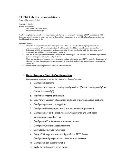
<strong>CCNA</strong> <strong>Lab</strong> <strong>Recommendations</strong><br />
Prepared By: Jeremy Archer<br />
Version 0.1 <br />
Notable Items Missing:<br />
<strong>Lab</strong>s on WLANs, SDM, VPNs<br />
Recommended Topologies<br />
<strong>The</strong> following list was compiled for my personal use. It may not accurately represent <strong>CCNA</strong> exam topics. This<br />
document is not intended to teach you how to do anything. Its purpose is to provide a list of the things that you<br />
should already know how to do.<br />
Important Notes:<br />
• <strong>The</strong>se lab recommendations have been prepared with no specific IP addressing requirements or<br />
recommendations. Determining the best IP address plan should be a consideration for each lab.<br />
• Debugging is highly encouraged throughout these labs. If you’re unfamiliar with the debugging tools /<br />
commands use IOS help or consult other resources.<br />
• <strong>The</strong> labs assume you understand these features and technologies. No attempts are made to explain their<br />
purpose or steps necessary to configure them.<br />
• Many labs can be done together (e.g. frame-relay configuration along with OSPF). Look for these types of<br />
labs and combine them so as to limit the amount of time dedicated to initial switch/router configuration,<br />
cabling, etc.<br />
• Recommended topologies will be added in a future version.<br />
1. Basic Router / Switch Configuration<br />
Complete these labs prior to starting the “Switch” or “Routing” sections.<br />
a. Configure hostname<br />
b. Compare start-up and running configurations (“show running-config” vs.<br />
“show start-config”)<br />
c. View the contents of the flash.<br />
d. View ‘show version’ information and note important output sections.<br />
e. Configure password encryption<br />
f. Configure the enable password and enable secret password.<br />
g. Configure SSH and Telnet Access w/ passwords and with local<br />
username/password access.<br />
h. Configure ACLs for remote telnet/ssh access<br />
i. Configure Console access password<br />
j. Upgrade/downgrade IOS image<br />
k. Copy IOS image and start-config to/from TFTP Server<br />
l. Configure config-register and observe boot behavior<br />
m. Configure boot system variable<br />
n. Walk through router setup mode.
o. Enable / Disable ‘ip subnet-zero’ and observe behavior by setting adding<br />
an interface to an “zero subnet” address.<br />
p. Test behavior difference between “ip classless” and “no ip classless”.<br />
q. Configure local usernames and passwords.<br />
r. Set up terminal history and view history<br />
s. Suspend, resume and view ssh/telnet session information.<br />
t. Identify configuration modes (global, int, router, etc)<br />
u. Save configuration changes (copy run start)<br />
v. Erase the start-config<br />
w. Reload the switch/router and observe the boot process.<br />
x. Document and troubleshoot network topology issues with CDP.<br />
y. Set up interface descriptions<br />
z. Create a login, exec and motd banner.<br />
aa. Enable logging timestamps (‘service timestamps’)<br />
bb. Create a local DHCP server on the router or switch and view DHCP<br />
leases.<br />
2. Switching<br />
a. Interface parameters and basic Switch Operation<br />
Prior to these labs, complete the “Basic Router / Switch Configuration” lab.<br />
i. Set interface description<br />
ii. Set interface speed and duplex<br />
iii. View CDP neighbors through interface (provided connected host<br />
supports CDP)<br />
iv. View MAC address-table for interface to determine MAC address<br />
of connected host.<br />
v. Set up management VLAN with VLAN interface and assigned IP<br />
Address.<br />
vi. Set a default-gateway.<br />
vii. Observe the LEDs on the front of the switch and their behavior.
viii. Display the contents of the MAC address-table.<br />
b. VLANs<br />
ix. Set the switch’s default gateway.<br />
i. Create multiple VLANs on L2 (or L3) switch and set their names.<br />
ii. Add switch ports (access ports) to VLANs<br />
1. Practice with the ‘int range xxx xxx’ command.<br />
iii. Create dot1q trunk ports between multiple switches<br />
iv. Set up VTP<br />
1. Using both ‘switch mode trunk’ and dynamic desirable and<br />
dynamic auto.<br />
2. Set up allowed VLAN trunks.<br />
1. Add switches in server, client and transparent mode.<br />
2. Configure VTP parameters including domain, password<br />
and VTP pruning.<br />
3. Set the VTP version number<br />
4. Create and delete VLANs and confirm changes on other<br />
VTP participants.<br />
5. Manage the vlans.dat file<br />
6. Examine ‘show vtp status’ output<br />
v. Create VLAN interfaces and confirm connectivity to those<br />
interfaces via client ping on associated VLAN interface.<br />
vi. Establish L3 interVLAN routing on L3 switch.<br />
c. EtherChannel<br />
1. Add hosts to access vlan ports on different IP subnets w/<br />
L3 switch as default GW. Ping between hosts to confirm<br />
interVLAN routing.<br />
i. Create EtherChannel port group between switches<br />
1. Add and remove interfaces to/from port-channel\
d. Spanning Tree<br />
2. Combine this lab with the STP lab and observe the cost<br />
for an EtherChannel trunk.<br />
3. Unplug one cable of the EtherChannel trunk and observe<br />
switch behavior.<br />
<strong>The</strong> following lab is best configured with 3 switches, each connected to the other two (Switch1<br />
connected to Switch2 and Switch3. Switch2 connected to Switch1 and Switch3, etc). In this way,<br />
it is easy to see the STP port states and alter the behavior of STP.<br />
Also, be sure to use ‘debug spanning-tree events’<br />
i. Configure a root bridge<br />
1. By setting VLAN id root primary and root secondary<br />
2. By altering VLAN id priority value<br />
ii. Disconnect a forwarding port and observe the behavior of a port<br />
as it moves through the STP port states.<br />
iii. Configure host ports for STP portfast<br />
iv. Configure BPDU guard for some interfaces and see the results<br />
(esp. when connected to another STP-enabled switch).<br />
v. Set up Per VLAN Spanning-Tree load balancing between trunk<br />
ports.<br />
vi. Alter interface cost to manipulate STP port selection.<br />
vii. Alter the STP type (RSTP vs. 802.1d) and observe the differences<br />
in “show spanning-tree vlan x’ and the port states as interfaces<br />
come up/down.<br />
e. Port Security<br />
i. Set up static MAC address port security<br />
ii. Set up dynamic MAC address security<br />
iii. Set up ‘sticky’ MAC address security<br />
iv. Set up port-security violation policy.<br />
v. Best practices for port security<br />
1. Create black hole VLAN (e.g. VLAN 666)
3. WANs<br />
2. Add unused ports to black hole VLAN<br />
3. Shutdown unused ports<br />
This is also a good section to practice your VLSM.<br />
4. Set unused ports to ‘switchport access vlan 666’<br />
a. Point to Point Serial Connections<br />
i. Serial point to point connections using PPP and HDLC<br />
1. Configure HDLC between two routers<br />
a. Adjust clock rate and bandwidth<br />
2. Configure PPP between two routers<br />
b. Frame-Relay Connections<br />
a. Set up PPP CHAP and PAP authentication<br />
b. Adjust clock rate and bandwidth<br />
i. Create fully meshed frame relay network with a single interface<br />
and single IP subnet with any DLCI configuration (rely on Inverse<br />
ARP and LMI) for the virtual circuits.<br />
ii. Using the same topology, use frame relay maps to map IP<br />
addresses and DLCI (disable Inverse ARP).<br />
iii. Using the same topology, use an interface DLCI to establish the<br />
PVC.<br />
iv. Practice changing the LMI type on all frame-relay connected<br />
routers.<br />
v. Practice the same configurations (items above) with Serial point-<br />
to-point sub-interfaces.<br />
vi. Configure multipoint sub-interface and reconfigure the network<br />
accordingly.<br />
vii. Configure frame relay network between 3 locations using<br />
multipoint sub-interface
4. Routing<br />
If you built a frame-relay network prior to this lab, that network will most likely work well for the routing labs. During<br />
these labs, repeatedly use the ‘show ip route’, ‘show ip route ’, and ‘show ip protocols’ commands to<br />
view the results of your work. I also recommend using a local loopback interface during your labs. This will allow you to<br />
see IP routing in action as the loopback networks begin appearing (and disappearing!) in your route table.<br />
This is also a good section to practice your VLSM.<br />
a. Connected networks<br />
i. Configure IP addresses on the router and observe the output of<br />
“show ip route”<br />
b. Static Routing<br />
c. RIP<br />
d. EIGRP<br />
i. Create default route using both next-hop and interface variables.<br />
ii. Create static route for one non-connected subnet.<br />
iii. Create weighted static route (sometimes called floating static<br />
route).<br />
i. Enable RIP<br />
ii. Set RIP version<br />
iii. Add networks to RIP<br />
iv. Set up at least one interface as passive.<br />
v. Configure manual IP route summarization<br />
vi. Practicing debugging RIP with ‘debug ip rip’<br />
i. Enable EIGRP on the router and select AS number.<br />
ii. Add networks to EIGRP configuration<br />
iii. Configure manual IP route summarization<br />
iv. Set the ‘ip hello-interval eigrp’ and ‘ip hold-time eigrp asn time’<br />
interface commands if necessary.<br />
v. Confirm interface bandwidth is set properly (you can practice<br />
altering this during the lab to view potential route changes). This<br />
is not a recommended practice!<br />
vi. Alter the delay value of an interface and observe the metric<br />
change in the ip routing table.
5. ACLs<br />
vii. Practice interpreting the output of ‘show ip eigrp topology’ and<br />
‘show ip eigrp topology all-links’.<br />
viii. Configure EIGRP authentication between two routers.<br />
ix.<br />
e. OSPF<br />
i. Throughout the lab, observe the output of ‘show ip ospf<br />
neighbor’, ‘show ip database’ and ‘show ip route’.<br />
ii. Configure OSFP on a point-to-point link (serial PPP) and a<br />
broadcast network (e.g. Ethernet). Observe the differences<br />
between the two with regards to the DR and BDR.<br />
iii. Configure each router’s router-id.<br />
iv. Configure each OSPF process with the appropriate ‘network’<br />
statements<br />
v. ‘show ip ospf interface interface-name to view the hello and dead<br />
timers for each connected interface.<br />
vi. Adjust the hello and dead time intervals.<br />
vii. Practice configuring OSFP with routers in two separate areas<br />
(loopback interfaces will work well for this).<br />
viii. Configure OSFP with two equal cost path. Obverse OSFP load<br />
balancing behavior and confirm both routes exist in the ‘show ip<br />
route’ output.<br />
This lab is best done with two hosts connected (or more) to two different interfaces on a route. Apply the ACLs to the<br />
router. Also, loopback addresses can help here for adding additional “hosts” on the other side of the router.<br />
a. Standard Access Lists (numbered)<br />
i. Create standard ACL (with a number) and identified source<br />
address and add a few lines to the ACL, including a remark.<br />
ii. Apply the ACL to an interface and test your results.<br />
iii. Practice altering the ACL by adding / removing lines, testing the<br />
iv.<br />
results each time.<br />
b. Standard Access Lists (named)
6. NAT<br />
i. Create standard ACL (with a name) and identified source address<br />
and add a few lines to the ACL, including a remark.<br />
ii. Apply the ACL to an interface and test your results.<br />
iii. Practice altering the ACL by adding / removing lines, testing the<br />
iv.<br />
results each time.<br />
c. Extended Access Lists (numbered)<br />
i. Create an extended ACL (with a number) and identified source,<br />
protocol type and destination port and address and add a few<br />
lines to the ACL, including a remark.<br />
ii. Apply the ACL to an interface and test your results.<br />
iii. Practice altering the ACL by adding / removing lines, testing the<br />
results each time.<br />
d. Extended Access Lists (named)<br />
i. Create an extended ACL (with a name) and identified source,<br />
protocol type and destination port and address and add a few<br />
lines to the ACL, including a remark.<br />
ii. Apply the ACL to an interface and test your results.<br />
iii. Practice altering the ACL by adding / removing lines, testing the<br />
results each time.<br />
e. Reflexive Access List (optional)<br />
a. Static NAT<br />
i. Translate inside host to public IP address.<br />
b. Dynamic NAT w/ pool and ACLs<br />
i. Translate inside hosts to pool of public IP addresses dynamically<br />
using an ACL to identify inside hosts and a pool to identify public<br />
IP addresses<br />
c. Dynamic NAT w/ interface, ACLs and Overload (PAT)
7. IPv6<br />
i. Translate inside hosts to public interface address using<br />
overloading (PAT)<br />
a. Enable IPv6 Routing (‘ipv6 unicast-routing’)<br />
b. Enable IPv6 cef<br />
c. Assign an IPv6 address to an interface using EUI-64 and without.<br />
d. Configure simple network (two routers connected with a Ethernet<br />
connection, each with an IPv6 loopback address) and test ping and simple<br />
static routes and ‘ipv6 router rip’ configuration.


