Analog Dialogue Volume 40, Number2, 2006
Analog Dialogue Volume 40, Number2, 2006
Analog Dialogue Volume 40, Number2, 2006

Create successful ePaper yourself
Turn your PDF publications into a flip-book with our unique Google optimized e-Paper software.
Power-Supply Management—<br />
Principles, Problems, and Parts<br />
By Alan Moloney [alan.moloney@analog.com]<br />
INTRODUCTION<br />
Power-supply designers are using flexible supply monitoring,<br />
sequencing, and adjustment circuits to manage their systems. 1<br />
This article discusses why and how.<br />
The monitoring and control of a growing number of power-supply<br />
voltage rails has been vital for safety, economy, durability, and<br />
proper operation of electronic systems for many years—especially<br />
for systems employing microprocessors. Determining whether a<br />
voltage rail is above a threshold or within an operating window—<br />
and whether that voltage is powered on or off in the correct<br />
sequence with respect to the other rails—is crucial to operational<br />
reliability and safety.<br />
Many methods exist to solve various aspects of this problem.<br />
For example, a simple circuit using a precision resistive divider,<br />
comparator, and reference can be used to determine whether<br />
the voltage on a rail is above or below a certain level. In reset<br />
generators, such as the ADM803, 2 these elements are combined<br />
with a delay element to hold devices—such as microprocessors,<br />
application-specific ICs (ASICs), and digital signal processors<br />
(DSPs)—in reset while powering up. This level of monitoring is<br />
adequate for many applications.<br />
Where multiple rails need to be monitored, multiple devices (or<br />
multichannel comparators and their associated circuitry) are used<br />
in parallel, but increasing opportunities call for monitoring ICs<br />
that do more than simple threshold comparison.<br />
For example, consider a common requirement for powersupply<br />
sequencing: an FPGA (field-programmable gate-array)<br />
manufacturer may specify that the 3.3-V core voltage must<br />
be applied 20 ms before the 5-V I/O (input/output) voltage to<br />
avoid possible damage when the device is powered up. Meeting<br />
such sequencing requirements may be as crucial for reliability<br />
as keeping the device’s supply voltage and temperature within<br />
specified operating limits.<br />
Also, the number of power rails in many applications has increased<br />
dramatically. Complex, expensive systems, such as LAN switches<br />
and cellular base stations, commonly have line cards with 10 or<br />
more voltage rails; but even cost-sensitive consumer systems, such<br />
as plasma TVs, can have as many as 15 separate voltage rails, many<br />
of which may require monitoring and sequencing.<br />
Many high-performance ICs now require multiple voltages. For<br />
example, separate core- and I/O voltages are standard for many<br />
devices. At the high end, DSPs may require up to four separate<br />
supplies per device. In many cases, numerous multisupply devices<br />
can coexist in a single system that contains FPGAs, ASICs,<br />
DSPs, microprocessors, and microcontrollers (as well as analog<br />
components).<br />
Many devices share standard voltage levels (such as 3.3 V),<br />
while others may require device-specific voltages. In addition, a<br />
particular standard voltage level may have to be independently<br />
furnished in numerous places. For example, separate analog- and<br />
digital supplies, such as 3.3 V ANALOG and 3.3 V DIGITAL, may be<br />
required. Generating the same voltage numerous times may be<br />
necessary to improve efficiency (e.g., memory rails running at<br />
hundreds of amperes) or to meet sequencing requirements (3.3 V A<br />
and 3.3 V B needed by separate devices at different times). All of<br />
these factors contribute to the proliferation of voltage sources.<br />
Voltage monitoring and sequencing can become quite complex,<br />
especially if a system must be designed to support a power-up<br />
sequence, a power-down sequence, and multiple responses to all<br />
possible fault conditions on the various supply rails at different<br />
points during operation. A central power management controller<br />
is the best way to solve this problem.<br />
As the number of supply voltages increases, there is a much<br />
higher probability of things going wrong. The risk increases<br />
in proportion to the number of supplies, number of elements,<br />
and complexity of the system. External factors also add risk.<br />
If, for example, the main ASIC is not completely characterized<br />
at the time of the initial design, the power-supply designer<br />
must commit to hardwiring voltage-monitoring thresholds<br />
and timing sequences that are subject to change as the ASIC<br />
specifications are developed. If the requirements change, the PC<br />
board may have to be revised—with obvious schedule- and cost<br />
implications. Furthermore, the supply voltage specifications for<br />
certain devices may change during their development. In such<br />
circumstances, a way to readily adjust supplies would be useful<br />
to any central power-system manager. In fact, the flexibility to<br />
monitor, sequence, and adjust the voltage rails of such systems<br />
is a vital necessity.<br />
Evaluating the robustness of the chosen fault protection and timing<br />
sequence can be a sizable job, so a device that simplifies this process<br />
will speed up board evaluation and reduce time to market. Fault<br />
logging and digitized voltage and temperature data are useful<br />
features, both in the field and in all phases of design from early<br />
PCB development through prototype evaluation.<br />
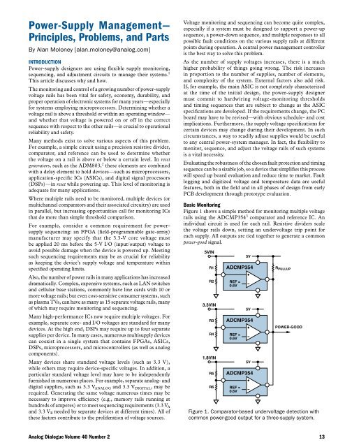
Basic Monitoring<br />
Figure 1 shows a simple method for monitoring multiple voltage<br />
rails using the ADCMP354 3 comparator and reference IC. An<br />
individual circuit is used for each rail. Resistive dividers scale<br />
the voltage rails down, setting an undervoltage trip point for<br />
each supply. All outputs are tied together to generate a common<br />
power-good signal.<br />
<strong>Analog</strong> <strong>Dialogue</strong> <strong>Volume</strong> <strong>40</strong> Number 2 13<br />
5VIN<br />
R1<br />
R2<br />
3.3VIN<br />
R3<br />
R4<br />
1.8VIN<br />
R5<br />
R6<br />
REF =<br />
0.6V<br />
5V<br />
ADCMP354<br />
REF =<br />
0.6V<br />
5V<br />
ADCMP354<br />
REF =<br />
0.6V<br />
5V<br />
ADCMP354<br />
R PULLUP<br />
POWER-GOOD<br />
Figure 1. Comparator-based undervoltage detection with<br />
common power-good output for a three-supply system.