ON MODELING OF HEAT EXCHANGERS IN MODELICA
ON MODELING OF HEAT EXCHANGERS IN MODELICA
ON MODELING OF HEAT EXCHANGERS IN MODELICA

You also want an ePaper? Increase the reach of your titles
YUMPU automatically turns print PDFs into web optimized ePapers that Google loves.
Proceedings of the 9th European Simulation Symposium, ESS'97, Oct 19-23, 1997, Passau, Germany<br />
<strong>ON</strong> <strong>MODEL<strong>IN</strong>G</strong> <strong>OF</strong> <strong>HEAT</strong> <strong>EXCHANGERS</strong> <strong>IN</strong> <strong>MODELICA</strong><br />
ABSTRACT<br />
It is demonstrated how Modelica TM is used in an application<br />
to develop models that are useful when solving<br />
real problems. Modelica is a new unified modeling<br />
language being developed in an international effort to<br />
promote object-oriented and non-causal modeling, and<br />
exchange of model libraries. The application is a heat<br />
exchanger where the media are liquids, typically water.<br />
This type of heat exchangers can be used for district<br />
heating of houses and for production of hot tap<br />
water. The model developed illustrates very nicely the<br />
power of Modelica. The modularization concepts support<br />
flexible model components which are easy to use and<br />
to adapt when making a model of a real system with<br />
heat exchangers. The concept of class parameters support<br />
medium parameterization and arrays of model components<br />
support discretization. The expressive power<br />
of Modelica allows complete listings of the developed<br />
model components to be given. The model produces simulation<br />
results that agree very well with measured data.<br />
<strong>IN</strong>TRODUCTI<strong>ON</strong><br />
A new language called Modelica 1 for physical modeling<br />
is developed in an international effort. The main objective<br />
is to develop a new unified modeling language<br />
which promotes exchange of models and model libraries<br />
and which supports non-causal modeling with true ordinary<br />
differential and algebraic equations and the use of<br />
object-oriented constructs to facilitate reuse of modeling<br />
knowledge.<br />
This paper demonstrates how Modelica is used in<br />
a specific application to develop models that are useful<br />
when solving real problems. The task is to develop a<br />
model for a heat exchanger where the media are liquids.<br />
The model developed is good enough to be used to solve<br />
real problems but simple enough to allow a detailed explanation<br />
in a conference paper. The paper discusses<br />
major issues such as decomposing the physical description<br />
of the heat exchanger from the properties of the media<br />
in a powerful way. The concepts of Modelica will be<br />
described and explained when needed in the modeling<br />
process. For more information on Modelica see Elmqvist<br />
and Mattsson (1997b), Elmqvist and Mattsson (1997a)<br />
and http://www.Dynasim.se/Modelica/.<br />
1 Modelica is a trade mark of the Modelica Design Group<br />
Sven Erik Mattsson<br />
Department of Automatic Control<br />
Lund Institute of Technology<br />
Box 118, SE-221 00 Lund, Sweden<br />
E-mail: SvenErik@control.LTH.se<br />
1<br />
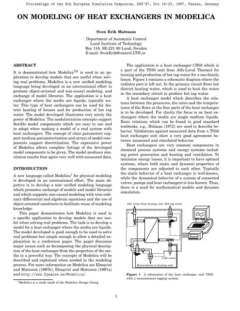
The application is a heat exchanger CB50 which is<br />
a part of the TS30 unit from Alfa-Laval Thermal for<br />
heating and production of hot tap water for a one-family<br />
house. Figure 1 contains a schematic diagram where the<br />
radiator part is left out. In the primary circuit flows hot<br />
district heating water, which is used to heat the water<br />
in the secondary circuit to produce hot tap water.<br />
A heat exchanger model which describes the relations<br />
between the pressures, the rates and the temperatures<br />
of the flows at the four ports of the heat exchanger<br />
is to be developed. For clarity the focus is on heat exchangers<br />
where the media are single medium liquids.<br />
Basic relations which can be found in good standard<br />
textbooks, e.g., Holman (1972) are used to describe behavior.<br />
Validations against measured data from a TS30<br />
heat exchanger unit show a very good agreement between<br />
measured and simulated behavior.<br />
Heat exchangers are very common components in<br />
chemical process systems and energy systems including<br />
power generation and heating and ventilation. To<br />
minimize energy losses, it is important to have optimal<br />
systems, where both static and dynamic properties of<br />
the components are adjusted to each other. Typically<br />
the static behavior of a heat exchanger is well-known,<br />
while the dynamical behavior of a system of connected<br />
valves, pumps and heat exchangers is less known. Thus,<br />
there is a need for mathematical models and dynamic<br />
simulation.<br />
Hot water from heating unit Hot tap water<br />
AVTQ20<br />
Cold water<br />
Recirculation to heating unit<br />
Figure 1 A schematics of the heat exchanger unit TS30<br />
with a measurement logging system.
BASIC MODEL STRUCTURE<br />
The first step of the object-oriented approach when<br />
modeling a component is to identify the ways in which<br />
it can interact with its environment. The behavior of<br />
a component can then either be described in terms<br />
of equations or as interconnected components. The<br />
modeling approach is hierarchical.<br />
A heat exchanger has two ducts with two ports each.<br />
These four ports constitute interfaces to which other<br />
components can be connected as shown in Figure 1.<br />
Variable types<br />
The essence of physical modeling is to describe behavior<br />
in terms of mathematical relations between physical<br />
quantities. In Modelica the type for pressure quantities<br />
is declared as<br />
type Pressure = Real(Unit = "Pa");<br />
where Real is the name of a predefined type. A real<br />
variable has a set of attributes such as unit of measure,<br />
minimum value, maximum value and initial value.<br />
To simplify the use of Modelica and to support compatibility,<br />
there is an extensive standard library of type<br />
definitions which is always available with every Modelica<br />
translator. The type definitions in this base library<br />
are based on ISO 1000 and its naming conventions for<br />
physical quantities.<br />
Connectors<br />
Interaction between model components is described by<br />
connecting connectors in Modelica and can graphically<br />
be represented by lines. A Modelica model defined<br />
graphically will contain graphical information specifying<br />
positions of submodels and connectors, paths for<br />
connections and graphical icon representations. Modelica<br />
defines a format for graphical annotations to make<br />
icons and model diagrams portable. All the graphical information<br />
is left out in the listings presented in this paper.<br />
Interactive browsing tools to list textual representations<br />
should be able to filter out graphical information<br />
to make the listings shorter and more transparent.<br />
Defining a set of connector classes is a good start<br />
when a library for a new application domain of is to be<br />
developed. A common set of such definitions, used in all<br />
components in the library, promotes compatibility.<br />
The status at a port of the heat exchanger can<br />
be described by one pressure, one temperature and<br />
one volume flow rate, if single medium liquid flows<br />
are assumed and if there is no interest in describing<br />
pressure, temperature or velocity profiles over the port<br />
area. To support this, a connector class is defined as<br />
connector FlowInlet<br />
Pressure p;<br />
flow VolumeFlowRate q;<br />
Temperature T;<br />
end FlowInlet;<br />
A connection between two connectors means that<br />
the components having the same names are connected<br />
2<br />
to each other down to the levels of simple quantities.<br />
The natural meaning of connecting quantities such as<br />
pressure, temperature, voltage and position, is that they<br />
should be equal, while for flow rates, currents, forces,<br />
torques etc. the physical meaning is that they should<br />
sum to zero. A sum-to-zero equation is generated when<br />
the prefix flow is used in the connector definition.<br />
In Modelica the convention is that a flow into the<br />
component is counted as positive.<br />
The interface<br />
The Modelica model<br />
partial model HEXShell "Base class for<br />
heat exchanger and section models"<br />
FlowInlet A1, A2, B1, B2 "Ports";<br />
parameter HEXParameters Pars;<br />
virtual model LiquidA = BasicLiquid;<br />
virtual model LiquidB = BasicLiquid;<br />
end HEXShell;<br />
outlines the interface part of a heat exchanger model.<br />
The keyword partial indicates that this model class is<br />
incomplete. At various places such as between the name<br />
of a class and its body or after a component declaration<br />
it is allowed to have a string. It is treated as a comment<br />
attribute and is meant to be a documentation that tools<br />
may display in special ways. Due to space limitations<br />
comments will be left out in the following.<br />
The model declares four ports: A1, A2, B1 and B2. The<br />
model will not assume any specific port to be inlet or<br />
outlet. Which ports that are inlets and which ports that<br />
are outlets depend on the actual flows. The two ducts of<br />
the heat exchanger will be called DuctA and DuctB. See<br />
Figure 2. The two ports of DuctA will be referred to as<br />
A1 and A2 and the two ports of duct B will analogously<br />
be referred to as B1 and B2. It will be assumed that the<br />
ports A1 and B1 are at one end of the heat exchanger<br />
and that the ports A2 and B2 are at the other end. For<br />
example, if there is a flow from A1 to A2 and a flow<br />
from B1 to B2 then the heat exchanger is operated as a<br />
parallel flow heat exchanger. But if the flow in DuctB is<br />
from B2 to B1 then the heat exchanger is operated as a<br />
counter flow heat exchanger.<br />
HEXShell declares a structured parameter Pars to<br />
describe physical properties such as dimensions. The<br />
A1<br />
B1<br />
DuctA<br />
Wall<br />
DuctB<br />
A2<br />
B2<br />
Figure 2 A conceptual picture of a heat exchanger.
keyword parameter specifies that Pars is constant during<br />
a simulation experiment, but can change value between<br />
experiments. The idea is to make it simple for a<br />
user to modify the behavior of a model. The physical parameters<br />
of the heat exchanger will be identified along<br />
the derivation of the behavior.<br />
LIQUID MODELS<br />
The heat exchanger model needs models of the liquids<br />
flowing in the two ducts. The model HEXShell defines<br />
two model classes parameters, LiquidA and LiquidB,for<br />
describing the properties of the media in the two ducts.<br />
The idea is to have a well defined interface between<br />
the description of the heat exchanger and the media to<br />
make it easy to modify the heat exchanger to cope with<br />
different media and descriptions of different complexity.<br />
The medium models are to be used in the duct models.<br />
On the heat exchanger level there is no use of medium<br />
models, but to make it easier for the user to change<br />
medium models, the classes of the medium models are<br />
made parameters of the heat exchanger model.<br />
The default class BasicLiquid specified by the model<br />
can be declared as<br />
model BasicLiquid<br />
Pressure p;<br />
Temperature T;<br />
Density rho;<br />
SpecificHeatCapacity c;<br />
end BasicLiquid;<br />
Each actual liquid model must at least contain the<br />
attributes p, T, rho and c, since an actual model must<br />
contain all public components of the default class.<br />
Note that an actual model need not be constructed by<br />
inheritance from the default class. Such a requirement<br />
would have made it difficult to use models developed<br />
at various places. There is just a requirement on<br />
agreement of the names of the components.<br />
In the future there will hopefully be standard models<br />
available in Modelica for many media in the same<br />
way as there are data bases for physical properties<br />
today. Medium models may actually be implemented as<br />
interfaces to such databases.<br />
For water it is often sufficient to use constant values<br />
for density and heat capacity. Such a model can be<br />
declared in the following way:<br />
model BasicWaterModel =<br />
BasicLiquid(rho = 1000, c = 4180);<br />
It means that rho and c become constant with the<br />
given values. It is not possible to change these values<br />
interactively between simulation runs. To allow this the<br />
model must be declared as<br />
model BasicWaterModel1 = BasicLiquid(<br />
redeclare parameter Density rho = 1000,<br />
redeclare parameter SpecificHeatCapacity c=4180<br />
);<br />
which turns rho and c into parameters and sets default<br />
values, which may be changed interactively between<br />
3<br />
simulation runs.<br />
It is important to include information that makes<br />
it possible to check the validity of a model. A simple<br />
approach is to specify ranges for the variables. The<br />
model for water is not valid when the water is freezing<br />
to ice or boiling to steam. For normal pressures, the<br />
condition can be expressed in terms of the temperature,<br />
which should be between 273 K and 373 K. To include<br />
this condition in our model we modify it as<br />
model BasicWaterModel2 =<br />
BasicLiquid(T(Min = 273, Max = 373),<br />
rho = 1000, c = 4180);<br />
A more general condition can be included in the<br />
equation section by specifying an assertion as<br />
assert condition;<br />
It is simple to make a liquid model in which the<br />
density is temperature dependent. It is just to include<br />
the relation and possibly declare some parameters. A<br />
model which assumes a linear expansion of volume with<br />
temperature may be declared as<br />
model BasicLinearLiquid<br />
extends BasicLiquid;<br />
parameter Temperature T0;<br />
parameter Density rho0 "at temperature T0";<br />
parameter CubicExpansionCoefficient alphaV;<br />
equation<br />
rho = rho0/(1 + alphaV*(T-T0));<br />
end BasicLinearLiquid;<br />
The statement “extends BasicLiquid” means that the<br />
model BasicLinearLiquid inherits all properties of<br />
BasicLiquid. The model BasicLinearLiquid specifies<br />
in addition three parameters and a affine relation<br />
between density and temperature.<br />
A model for water is specified as<br />
model BasicLinearWaterModel =<br />
BasicLinearLiquid(T(Min = 273, Max = 373),<br />
T0 = 293, rho0 = 998,<br />
alphaV = 0.00018, c = 4180);<br />
BEHAVIOR DESCRIPTI<strong>ON</strong><br />
Heat exchangers may internally look very different, but<br />
the basic idea is to let two media, which flow on the<br />
two sides of the wall, exchange heat through the wall<br />
without being mixed. A heat exchanger consists from a<br />
conceptual point of view of two ducts with a common<br />
wall through which heat can flow. See Figure 2. The<br />
model will be based on this conceptual view.<br />
The complexity of using partial differential equations<br />
to describe the heat transfer from the hot side<br />
to the cold side can be avoided, since we do not have<br />
the ambition to describe the internal behavior of the<br />
heat exchanger for example in order to calculate thermal<br />
stresses. A common approach which divides the<br />
heat exchanger into a number of slices or sections along<br />
the direction of the flow will be taken. Such a section<br />
consists of two duct sections and one wall section.
A DUCT SECTI<strong>ON</strong> MODEL<br />
Port1 Port2<br />
Wall<br />
Figure 3 The connectors of a duct section.<br />
A Modelica model for a duct section is given in Listing 1.<br />
As indicated in Figure 3 three connectors are needed.<br />
These are defined first in the model HEXDuctSection.<br />
There are Port1 and Port2 for the liquid flow and Wall<br />
to describe interaction with the wall. Then the model<br />
defines a parameter record, Pars, and a class parameter,<br />
Liquid, for the liquid properties in order to make it easy<br />
to exchange medium models.<br />
Let us consider the behavior description and discuss<br />
the equations in turn.<br />
Assume that the duct is filled all the time and that<br />
the liquid is incompressible. Then the mass balance<br />
degenerates to the fact that the volume inflow rates at<br />
the two ports must sum to zero.<br />
q1 + q2 0 (1)<br />
The model HEXDuctSection uses Port1.q to represent<br />
the volume inflow rate, q1, andPort2.q to represent q2.<br />
Thus Equation (1) becomes Port1.q + Port2.q in the<br />
model HEXDuctSection.<br />
The pressure drop over the duct is modeled as<br />
p1 − p2 ρ<br />
C 2 q1q1<br />
v<br />
(2)<br />
where p1 and p2 are the pressures at the two ports, ρ<br />
is the density of the liquid and Cv is a constant.<br />
The heat balance of a duct gives<br />
dH<br />
dt Φw + Φ1 + Φ2<br />
(3)<br />
where H is the enthalpy. The left hand side of the<br />
balance equation represents the change of the thermal<br />
energy in the duct. The first term of the right hand side,<br />
Φw, is the rate of the heat flow across the wall into the<br />
duct and Φ1 and Φ2 are the changes of thermal energy<br />
of the duct due to the flow through the two ends of the<br />
duct;<br />
Φi ciρ iqiTi, i 1, 2 (4)<br />
where the factors of the right hand side represent<br />
properties of the flow at the port; ci is the specific heat<br />
capacity, ρ i is the density, qi is the volume flow rate and<br />
Ti is the temperature.<br />
The enthalpy is given by<br />
H cρ VT (5)<br />
4<br />
connector WallConnector<br />
VolumeFlowRate q;<br />
Temperature T1, T2, T;<br />
flow HeatFlowRate Phi;<br />
end WallConnector;<br />
record DuctParameters<br />
Volume V;<br />
Area Cv;<br />
end DuctParameters;<br />
model HEXDuctSection<br />
FlowInlet Port1, Port2;<br />
WallConnector Wall;<br />
parameter DuctParameters Pars;<br />
virtual model Liquid = BasicLiquid;<br />
Liquid L1 "The liquid at Port1.";<br />
Liquid L2 "The liquid at Port2.";<br />
Temperature T;<br />
Density rho;<br />
SpecificHeatCapacity c;<br />
Enthalpy H;<br />
equation<br />
// Hydraulics<br />
Port1.q + Port2.q = 0;<br />
Port1.p - Port2.p =<br />
rho/Pars.Cv^2*abs(Port1.q)*Port1.q;<br />
// Thermodynamics<br />
der(H) = Wall.Phi +<br />
L1.c*L1.rho*Port1.q*Port1.T +<br />
L2.c*L2.rho*Port2.q*Port2.T;<br />
H = rho*Pars.V*c*T;<br />
T = if Port1.q > 0 then Port2.T else Port1.T;<br />
rho = if Port1.q > 0 then L2.rho else L1.rho;<br />
c = if Port1.q > 0 then L2.c else L1.c;<br />
// Communication<br />
Wall.q = Port1.q; Wall.T = T;<br />
Wall.T1 = Port1.T; Wall.T2 = Port2.T;<br />
L1.p = Port1.p; L2.p = Port2.p;<br />
L1.T = Port1.T; L2.T = Port2.T;<br />
end HEXDuctSection;<br />
Listing 1 A model of a duct section.<br />
where V is the volume of the duct and T is a representative<br />
mean temperature of the liquid. The specific<br />
heat capacity, c, and the density, ρ are to be taken at<br />
that temperature. The temperature at the outlet will be<br />
assumed to be T;<br />
T if q1 > 0 then T2 else T1 (6)<br />
Validations against measured data indicate that this is<br />
a valid approximation so it seems not useful to introduce<br />
more dynamics or delays from T to the temperature<br />
at the outlet. The approach to view T to be the mean<br />
value of the temperatures at the port, T (T1+T2)/2,<br />
has the drawback that an increase of the temperature<br />
at the inlet implies an instantaneous decrease of the<br />
temperature at the outlet, since T due to the dynamics<br />
does not respond instantaneously.<br />
The last four lines set up the interaction with the<br />
wall and the liquid models.
A <strong>HEAT</strong> TRANSFER MODEL<br />
A Modelica model for a wall section is given in Listing 2.<br />
First, it defines two connectors WA and WB for the interaction<br />
with the ducts. The meaning of the parameters<br />
and the other quantities will be explained below when<br />
we discuss the equations in turn.<br />
The model of the heat transfer through the wall<br />
focuses on the heat flow across the wall. Heat flow along<br />
the wall is neglected as well as the heat capacity of the<br />
wall, which means<br />
Φ A + Φ B 0; (7)<br />
The heat flow rate across the wall is modeled as<br />
Φ B ΔTm/R (8)<br />
where R is the overall thermal resistance between the<br />
two ducts and ΔTm is a suitable mean temperature<br />
difference between the two ducts along the wall.<br />
To obtain a model that has a statically correct<br />
behavior, the common approach is to take ΔTm as the<br />
log-mean temperature difference, ΔTlm, defined as<br />
ΔTlm ΔT1 − ΔT2<br />
ln(ΔT1/ΔT2)<br />
(9a)<br />
where ΔT1 TA,1 − TB,1 and ΔT2 TA,2 − TB,2 are<br />
the temperature differences at the two ends of the duct.<br />
The formula is badly conditioned if ΔT1 ΔT2 so when<br />
ΔT1 − ΔT2 0.05*max(abs(DT1),abs(DT2)))<br />
then (DT1-DT2)/ln(DT1/DT2)<br />
else if DT1*DT2 == 0 then 0.5*(DT1+DT2)<br />
else 0.5*(DT1+DT2)*<br />
(1-sqr(DT1-DT2)/(DT1*DT2)*<br />
(1 + sqr(DT1-DT2)/(DT1*DT2)/2)/12);<br />
// Thermal resistance<br />
R = RA + Rw + RB + Pars.Rf;<br />
RA = 1/(Pars.SA.h0*abs(WA.q/Pars.SA.q0)^Pars.SA.n*<br />
(1+Pars.SA.ah*(WA.T-Pars.SA.T0))*Pars.A);<br />
RB = 1/(Pars.SB.h0*abs(WB.q/Pars.SB.q0)^Pars.SB.n*<br />
(1+Pars.SB.ah*(WB.T-Pars.SB.T0))*Pars.A);<br />
Rw = Pars.d/(Pars.lambda*Pars.Y*Pars.A);<br />
end HEXWallSection;<br />
Listing 2 A model of the heat exchanger wall.<br />
h0, nh, qh and ah are constants to be identified from<br />
measured data and T0 is an estimation of the mean<br />
value of lowest and highest appearing temperatures.<br />
The thermal resistance of the wall, Rw, is calculated<br />
as<br />
Rw <br />
d<br />
(12)<br />
λ YAw<br />
where d is the thickness of the wall, λ is the thermal<br />
conductivity of the wall material and Y is a correction<br />
factor for the corrugation of the wall.<br />
The model HEXWallSection has been implemented<br />
as a primitive model, where the behavior is described<br />
directly in terms of equations. When more elaborate<br />
models are to be developed it is recommendable to<br />
decompose the model into thermal resistors in series.
ecord HEXParameters<br />
DuctParameters DuctA, DuctB;<br />
WallParameters Wall;<br />
end HEXParameters;<br />
model HEXn<br />
extends HEXShell;<br />
parameter Integer n "Number of sections";<br />
HEXDuctSection<br />
DuctA[n](Pars(V = Pars.DuctA.V/n,<br />
Cv = sqrt(n)*Pars.DuctA.Cv),<br />
redeclare model Liquid = LiquidA),<br />
DuctB[n](Pars(V = Pars.DuctB.V/n,<br />
Cv = sqrt(n)*Pars.DuctB.Cv),<br />
redeclare model Liquid = LiquidB);<br />
HEXWallSection<br />
Wall[n](Pars = WallPartPars(fraction = 1.0/n,<br />
Wall = Pars.Wall));<br />
equation<br />
connect(A1, DuctA[1].Port1);<br />
connect(B1, DuctB[1].Port1);<br />
for i in 1:n-1 loop<br />
connect(DuctA[i].Port2, DuctA[i+1].Port1);<br />
connect(DuctB[i].Port2, DuctB[i+1].Port1);<br />
end for;<br />
connect(DuctA[n].Port2, A2);<br />
connect(DuctB[n].Port2, B2);<br />
for i in 1:n loop<br />
connect(DuctA[i].Wall, Wall[i].WA);<br />
connect(DuctB[i].Wall, Wall[i].WB);<br />
end for;<br />
end HEXn;<br />
Listing 3 The base model of a heat exchanger.<br />
A <strong>HEAT</strong> EXCHANGER MODEL<br />
A model of a heat exchanger can now be defined by<br />
putting together a number of duct section models and<br />
wall section models. See Listing 3.<br />
The record type HEXParameters, which is referred by<br />
the shell model HEXShell, is defined as the aggregation<br />
of the parameters of the two ducts and the wall.<br />
The model HEXn uses HEXShell as a base class and<br />
specifies in addition two arrays of duct section models<br />
and one array of wall section models, which are of the<br />
same length, parameterized by n. The equation section<br />
connects the pieces to each other and to the ports of<br />
HEXn.<br />
The declarations of the component models include hierarchical<br />
parameter propagation to set default values<br />
for the parameters of the elements. Some of the parameters<br />
have to be recalculated, since the section parts have<br />
other physical dimensions than the heat exchanger itself.<br />
To explain how this is done, let us in more detail<br />
discuss one of the declarations, for example<br />
HEXDuctSection<br />
DuctA[n] (Pars(V = Pars.DuctA.V/n,<br />
Cv = sqrt(n)*Pars.DuctA.Cv),<br />
redeclare model Liquid = LiquidA);<br />
The declaration sets the two simple parameters Pars.V<br />
and Pars.Cv individually in terms of the parameters<br />
6<br />
of HEXn. The construct V = Pars.DuctA.V/n means that<br />
the default value of DuctA[i].Pars.V should be set to<br />
Pars.DuctA.V/n for 1 ≤ i ≤ n. Note, that the right hand<br />
side is resolved in the scope of HEXn. The declaration<br />
also sets an actual model LiquidA to the virtual model<br />
Liquid.<br />
The wall has more parameters, where all but two<br />
parameters should just be copied when propagated to its<br />
sections. It is convenient to use a function for this since<br />
it allows multiple assignments. A function declaration<br />
is similar to a class declaration, but it starts with the<br />
keyword function. The input arguments are marked<br />
with the keyword input and the result arguments of<br />
the function are marked with the keyword output.<br />
Functions have an algorithm section instead of an<br />
equation section. The algorithm section should contain<br />
ordered assignment statements, if-then-else constructs<br />
and loops.<br />
function WallPartPars<br />
input Real fraction;<br />
input WallParameters Wall;<br />
output WallParameters WallPart;<br />
algorithm<br />
WallPart := Wall;<br />
WallPart.A := fraction*Wall.A;<br />
WallPart.Rf := Wall.Rf/fraction;<br />
end WallPartPars;<br />
All parameters are copied in the first statement. Then<br />
two of them are modified.<br />
VALIDATI<strong>ON</strong> <strong>OF</strong> THE MODEL<br />
When this is written in August 1997, there is yet<br />
no Modelica translator which can transform the heat<br />
exchanger model developed above to a representation<br />
which can be simulated. There is a translator that can<br />
handle a subset of Modelica, but it cannot handle arrays<br />
of components.<br />
The mathematical model described above has earlier<br />
been implemented in the object-oriented language<br />
Omola [Mattsson et al. (1993), Andersson (1994)] and<br />
simulated in the interactive environment OmSim. The<br />
Omola model was validated against measurements from<br />
a heat exchanger of type CB50 from Alfa-Laval Thermal.<br />
A description of the experiments and comparisons<br />
done can be found in Ericsson and Östberg (1993). The<br />
result of the validation is that there is a good agreement<br />
between simulated and measured behavior. The Omola<br />
model and the result of the validation have also been<br />
published in Mattsson et al. (1994).<br />
To indicate that the mathematical model developed<br />
above is good, we will here show a typical result from<br />
that validation. In the experiment the flow of hot water<br />
from the district heating unit was kept constant with<br />
a rate of 0.25 l/s and the consumption of tap water<br />
was varied as shown in Figure 4. For CB50 the volume<br />
of each duct is 0.094 liters and the area of the heat<br />
transporting wall is 1.1 m 2 . The measured time series<br />
of the tap water flow was used as input to a simula-
0.4<br />
0.3<br />
0.2<br />
0.1<br />
Flow rate [l/s]<br />
Tap water<br />
Hot water<br />
0<br />
0 200 400 600 800 1000 1200<br />
Time [s]<br />
Temperature [ ○ C]<br />
60<br />
40<br />
20<br />
Hot water in<br />
Tap water out<br />
Hot water out<br />
Tap water in<br />
0<br />
0 200 400 600 800 1000 1200<br />
Time [s]<br />
Figure 4 Result of a validation experiment. The upper<br />
figure shows measured flow rates and the lower figure<br />
shows measured temperatures (dashed lines) and simulated<br />
temperatures (solid lines).<br />
tion model where the heat exchanger was modeled by<br />
three sections. The simulated and measured temperatures<br />
at the outlets are shown in Figure 4. The agreement<br />
between measured and simulated temperatures at<br />
the outlets are very good. The static error on the hot side<br />
may depend on bad positioning of the temperature sensor.<br />
All temperature sensors were calibrated carefully<br />
before the experiments.<br />
C<strong>ON</strong>CLUSI<strong>ON</strong>S<br />
An object-oriented model of a heat exchanger unit operating<br />
under normal conditions has been developed. The<br />
model has been validated against measurements from a<br />
real system and the agreement between measured and<br />
simulated behavior is very good.<br />
Use of the new general object-oriented modeling language<br />
Modelica has been illustrated and discussed in<br />
detail for an important technical system. It has been<br />
demonstrated how Modelica promotes flexible model<br />
components. In particular it is demonstrated that Modelica<br />
indeed supports decomposition of media properties<br />
from physical properties of the heat exchanger. It is very<br />
easy to change media or the complexity of media models.<br />
It is not feasible to make a model that describes<br />
all situations equally well. In normal operation of a<br />
heat exchanger, the flows do not change directions.<br />
The model developed can from a structural point of<br />
view handle flows that change directions. However, all<br />
behaviour descriptions are not good for small flows.<br />
For example, the model for the heat transfer between<br />
7<br />
a liquid and the wall describes the behaviour for a<br />
forced flow at stationary conditions. It means that the<br />
model does not predict any heat transfer for zero flow<br />
rate. However, the use of object-oriented ideas makes it<br />
possible to easily modify the model when the equations<br />
are available.<br />
Modelica is designed to support reuse of model<br />
knowledge. The ideal world is that a user who wants<br />
to solve a real problem finds a ready-made model in<br />
his model library. The second best option is that he<br />
is able to develop the desired model by just putting<br />
together components from the model library by using a<br />
graphical editor. This paper focuses on development of<br />
such library components for heat exchangers. The need<br />
for flexible and reliable model components means that<br />
a developer of such a model library must define general<br />
and parameterized components and he or she must<br />
also provide redundant information such as declaration<br />
of variables to allow automatic consistency checking.<br />
Modelica supports this task very well.<br />
Acknowledgements<br />
The work has been supported by the Swedish National<br />
Board for Technical Development under project<br />
P9304688 “Modeling and simulation of complex systems”<br />
and by Sydkraft under project 391 “Modeling and<br />
control of energy processes”. The provision of a heat exchanger<br />
system for experiments from Alfa Laval Thermal<br />
is gratefully acknowledged.<br />
REFERENCES<br />
ANDERSS<strong>ON</strong>,M.(1994): Object-Oriented Modeling and Simulation<br />
of Hybrid Systems. PhD thesis ISRN LUTFD2/TFRT-<br />
-1043--SE, Department of Automatic Control, Lund Institute<br />
of Technology, Lund, Sweden.<br />
ELMQVIST, H. and S. E. MATTSS<strong>ON</strong> (1997a): “An introduction to<br />
the physical modeling language Modelica.” In Proceedings<br />
of the 1997 European Simulation Symposium (ESS’97).<br />
The Society for Computer Simulation, Passau, Germany.<br />
ELMQVIST, H. and S. E. MATTSS<strong>ON</strong> (1997b): “Modelica —<br />
The next generation modeling language, An international<br />
design effort.” In Proceedings of the 1st World Congress<br />
on System Simulation. Singapore.<br />
ERICSS<strong>ON</strong>, M. and P. ÖSTBERG (1993): “Dynamisk provning av<br />
värmeväxlarsystem (Dynamic testing of heat exchanger<br />
systems).” Master Thesis ISRN LUTFD2/TFRT--5490--<br />
SE. Department of Automatic Control, Lund Institute of<br />
Technology, Lund, Sweden.<br />
HOLMAN, J.P.(1972): Heat Transfer, third edition. McGraw-<br />
Hill Book Company.<br />
MATTSS<strong>ON</strong>, S.E.,M.ANDERSS<strong>ON</strong>, and K. J. ÅSTRÖM (1993):<br />
“Object-oriented modeling and simulation.” In L<strong>IN</strong>KENS,<br />
Ed., CAD for Control Systems, pp. 31–69. Marcel Dekker,<br />
Inc., New York.<br />
MATTSS<strong>ON</strong>, S.E.,M.ERICS<strong>ON</strong>, and P. ÖSTBERG (1994): “An<br />
object-oriented model of a heat-exchanger unit.” In Proceedings<br />
of the European Simulation Multiconference,<br />
ESM’94, pp. 297–303. SCS, The Society for Computer Simulation,<br />
Barcelona, Spain.