Simulation of IGBT converter - Model Order Reduction
Simulation of IGBT converter - Model Order Reduction
Simulation of IGBT converter - Model Order Reduction

Create successful ePaper yourself
Turn your PDF publications into a flip-book with our unique Google optimized e-Paper software.
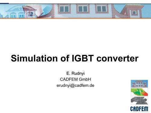
<strong>Simulation</strong> <strong>of</strong> <strong>IGBT</strong> <strong>converter</strong><br />
E. Rudnyi<br />
CADFEM GmbH<br />
erudnyi@cadfem.de
Outline<br />
The work has been done for the ECPE workshop Thermal<br />
Engineering <strong>of</strong> Power Electronics Systems, 2009<br />
Overview<br />
Thermal <strong>Simulation</strong> in Icepak<br />
Compact Thermal <strong>Model</strong> through <strong>Model</strong> <strong>Order</strong> <strong>Reduction</strong><br />
1
European Center for Power Electronics<br />
2
<strong>IGBT</strong> Converter<br />
Insulated Gate Bipolar Transistor:<br />
Very efficient – thermal losses about just 5%<br />
However 20 kW <strong>converter</strong> produces 1 kW power dissipation.<br />
Electrothermal simulation is required:<br />
3<br />
Electrical properties <strong>of</strong> <strong>IGBT</strong> depends on temperature;<br />
Too high temperatures reduces reliability and durability.<br />
T j<br />
T c
The <strong>Model</strong> <strong>of</strong> the Converter<br />
4<br />
Original <strong>Model</strong><br />
<strong>Model</strong> in Icepak<br />
<strong>Model</strong> in Icepro
Simplifying the Heat sink In Icepro<br />
5
Power dissipation, materials, boundary conditions<br />
6
Mesh<br />
7
Solution - convergence<br />
8
Typical <strong>Simulation</strong> Results<br />
9
Comparison with Experimental Measurements<br />
10<br />
80<br />
70<br />
60<br />
50<br />
40<br />
30<br />
20<br />
10<br />
0<br />
trial1 trial2 trial3 trial4<br />
T1ex<br />
T1sim<br />
T2ex<br />
T2sim<br />
Tref_ex<br />
Tref_sim
Transient <strong>Simulation</strong> in Icepak<br />
Flow is developed: We need to<br />
solve only energy equation.<br />
11
From Finite Elements to System <strong>Simulation</strong><br />
12<br />
Physics &<br />
Geometry<br />
System <strong>of</strong><br />
FEM MOR<br />
n ODEs<br />
Electrothermal <strong>Simulation</strong> with <strong>IGBT</strong>s:<br />
From ANSYS Workbench to System Level<br />
Reduced<br />
System <strong>of</strong><br />
r
<strong>Model</strong> <strong>Order</strong> <strong>Reduction</strong><br />
Relatively new technology<br />
Solid mathematical background:<br />
13<br />
Approximation <strong>of</strong> large scale<br />
dynamic systems<br />
Dynamic simulation:<br />
Harmonic or transient simulation<br />
Industry application level:<br />
Linear dynamic systems
<strong>Model</strong> <strong>Reduction</strong> as Projection<br />
Projection onto lowdimensional<br />
subspace<br />
14<br />
x Vz<br />
x = V<br />
<br />
z<br />
E<br />
How to find<br />
subspace?<br />
Mode<br />
superposition is<br />
not the best way<br />
to do it.<br />
V<br />
T<br />
Ex Kx<br />
Bu<br />
T<br />
T<br />
EVz<br />
V<br />
KVz<br />
V<br />
Bu<br />
E r
Transferring <strong>Model</strong> from Icepak to Workbench<br />
15<br />
Q <br />
hA <br />
( T Tbulk<br />
)
MOR for ANSYS: http://<strong>Model</strong><strong>Reduction</strong>.com<br />
16<br />
Workbench<br />
ANSYS <strong>Model</strong><br />
FULL files<br />
Mx<br />
<br />
Ex<br />
<br />
Kx<br />
y Cx<br />
<br />
Bu<br />
Linear Dynamic<br />
System, ODEs<br />
Current version 2.5<br />
Simulink,<br />
Simplorer, VerilogA,<br />
…<br />
Small dimensional<br />
matrices<br />
MOR Algorithm
<strong>Model</strong> <strong>Reduction</strong>: Inputs and Outputs<br />
12 inputs and outputs have been defined<br />
17
<strong>Model</strong> reduction<br />
Dimension <strong>of</strong> the model in ANSYS is about 900 K DoFs.<br />
Dimension <strong>of</strong> the reduced model is 15 DoFs per input = 15*12 = 180.<br />
The reduced model covers all heat sources and thermal cross talk at<br />
once.<br />
Transient simulation when 1 W has been applied only on device.<br />
Step response.<br />
On the next slides there is comparison between the simulation <strong>of</strong> the<br />
full model in ANSYS and the reduced model for T_A1. This curve<br />
corresponds to thermal impedance.<br />
18
Comparison<br />
Red line – ANSYS, green line – reduced model. Difference is close to<br />
the line thickness. For such accuracy, one needs 15 DoFs per input.<br />
19
Comparison<br />
Relative error between results in ANSYS and reduced model.<br />
20
Comparison with Measurements<br />
Cooling curves from the stationary state with:<br />
75 W on <strong>IGBT</strong>s<br />
0 W on diodes<br />
T ambient = 28.5<br />
Using point T2 (P2) and the average on the upper face <strong>of</strong> <strong>IGBT</strong> T_B2<br />
for comparison with the measurements<br />
21
Temperatures on <strong>IGBT</strong>s<br />
22
Temperatures under <strong>IGBT</strong>s<br />
23
<strong>Simulation</strong> in Simplorer<br />
24<br />
E1<br />
z_up<br />
P1<br />
P2<br />
P3<br />
P4<br />
z_vp<br />
Ambient<br />
P_ REF<br />
Q<br />
P5<br />
P6<br />
P7<br />
P8<br />
z_wp<br />
z_um z_vm z_wm<br />
P1 2<br />
P1 1<br />
P1 0<br />
P9<br />
Thermal Domain<br />
Electrical Domain<br />
VM311 R6 R5 R4<br />
+<br />
V<br />
IN_A<br />
IN_B<br />
IN_C<br />
U2<br />
Simplorer4<br />
A<br />
A<br />
A<br />
OUT_A<br />
OUT_B<br />
OUT_C<br />
R1 R2 R3<br />
A<br />
B<br />
C<br />
Induction_Motor_20kW<br />
N<br />
ROT1<br />
ROT2<br />
Mechanical<br />
Domain<br />
0<br />
MASS_ROT1
Conclusion<br />
Icepak to quickly simulation <strong>IGBT</strong> <strong>converter</strong><br />
Compact dynamic thermal model are necessary<br />
Transfer to ANSYS Workbench with convection boundary conditions<br />
Compact thermal model are obtained through model reduction<br />
25