

Simulation of a thermal model of a surface cooled squirrel cage ...
Simulation of a thermal model of a surface cooled squirrel cage ...
Simulation of a thermal model of a surface cooled squirrel cage ...

Create successful ePaper yourself
Turn your PDF publications into a flip-book with our unique Google optimized e-Paper software.
<strong>Simulation</strong> <strong>of</strong> a <strong>thermal</strong> <strong>model</strong> <strong>of</strong> a <strong>surface</strong> <strong>cooled</strong> <strong>squirrel</strong> <strong>cage</strong> induction machine by means <strong>of</strong> the<br />
SimpleFlow-library<br />
allow the <strong>model</strong>ling <strong>of</strong> complex applications like<br />
the cooling <strong>of</strong> an electric machine.<br />
3 Thermal Equivalent Circuit<br />
The components <strong>of</strong> a <strong>thermal</strong> equivalent<br />
circuit can be imported from<br />
Modelica.Thermal.HeatTransfer. The <strong>thermal</strong><br />
networks are designed in the style <strong>of</strong> electrical<br />
components and circuits. The components <strong>of</strong><br />
such a network are:<br />
• Nodes are regions <strong>of</strong> constant temperature.<br />
The potential <strong>of</strong> a node represents the absolute<br />
temperature <strong>of</strong> that node. The SI unit<br />
<strong>of</strong> the absolute temperature is K.<br />
• A loss source in the <strong>thermal</strong> circuit is equivalent<br />
to a current source in an electric circuit.<br />
There are loss sources where the precalculated<br />
losses have to be corrected by the actual<br />
temperature <strong>of</strong> the corresponding node in order<br />
to consider copper losses correctly. Other<br />
loss sources such as iron losses do not need<br />
a temperature dependent correction. The SI<br />
unit <strong>of</strong> the heat flow is W.<br />
• Thermal resistors represent regions <strong>of</strong> heat<br />
conduction. For technical application such as<br />
electric machines, heat transfer is mainly heat<br />
conduction and convection. Heat radiation is<br />
usually not considered. The SI unit <strong>of</strong> a <strong>thermal</strong><br />
conductance is K / W. A <strong>thermal</strong> conductor<br />
is the reciprocal <strong>of</strong> a <strong>thermal</strong> resistor.<br />
Its SI unit is W / K.<br />
• Thermal capacitors represent the ability <strong>of</strong><br />
storing heat energy in a certain region. The<br />
SI unit <strong>of</strong> a <strong>thermal</strong> capacitor is Ws/K.<br />
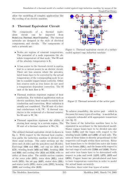
The utilized <strong>thermal</strong> equivalent circuit is shown in<br />
fig. 1. With respect to the <strong>thermal</strong> heat conduction<br />
paths the induction machine is divided into<br />
three axial sections. The outer sections are the<br />
drive end (A-side) and the non-drive end (B-side).<br />
End-rings (ERA and ERB), end cap air (AIA and<br />
AIB), winding heads (WHA and WHB), housing (HOA<br />
and HOB) and cooling ribs (RIA and RIB) refer to<br />
either <strong>of</strong> these sides. The middle section consists<br />
<strong>of</strong> the rotor yoke (RYO), rotor slots (RSL), rotor<br />
teeth (RTO), the air gap (AGP), stator slots (SSL)<br />
and stator teeth (STO), stator yoke (SYO), housing<br />
(HOM) and cooling ribs (RIM).<br />
¡¢£¤¥¦§ ¨©¥<br />
¡<br />
§ §<br />
§ §<br />
<br />
<br />
<br />
§<br />
<br />
<br />
<br />
<br />
<br />
<br />
§<br />
<br />
§<br />
<br />
<br />
§ §<br />
<br />
<br />
<br />
<br />
<br />
<br />
<br />
<br />
<br />
<br />
<br />
<br />
<br />
<br />
<br />
<br />
<br />
<br />
<br />
<br />
<br />
¡¢£¤¥¦<br />
Figure 1: Thermal equivalent circuit <strong>of</strong> a <strong>surface</strong><br />
<strong>cooled</strong> <strong>squirrel</strong> <strong>cage</strong> induction machine<br />
<br />
<br />
<br />
<br />
<br />
<br />
<br />
<br />
<br />
<br />
<br />
<br />
<br />
<br />
<br />
<br />
<br />
<br />
<br />
<br />
<br />
<br />
<br />
<br />
<br />
<br />
Figure 2: Thermal network <strong>of</strong> the active part<br />
To achieve reusability, the active part – which is<br />
the same for many types <strong>of</strong> cooling – is <strong>model</strong>led as<br />
a separate sub<strong>model</strong> with appropriate connectors<br />
(see fig. 2)<br />
The losses <strong>of</strong> the induction machine have to be<br />
separated in accordance to the introduced <strong>model</strong>.<br />
Stator copper losses have to be divided into slot<br />
losses (LSSL) and the losses with respect to the<br />
winding heads (LWHA and LWHB) <strong>of</strong> each side. The<br />
ratio <strong>of</strong> these losses is directly proportional to the<br />
respective coil length within these sections. Rotor<br />
heat losses have to be divided into rotor slot losses<br />
(or bar losses; LRSL), and the losses with respect to<br />
the end rings <strong>of</strong> each side (LSRA and LEAB). Stator<br />
and rotor iron losses have to be determined with<br />
respect to yoke and teeth (LSYO, LSTO, LRYO and<br />
LRTO). Copper losses are precalculated and have<br />
to have temperature correction in order to <strong>model</strong><br />
the actual losses accurately.<br />
Therefore, there exist four types <strong>of</strong> nodes:<br />
The Modelica Association 215 Modelica 2005, March 7-8, 2005


