

Simulation of a thermal model of a surface cooled squirrel cage ...
Simulation of a thermal model of a surface cooled squirrel cage ...
Simulation of a thermal model of a surface cooled squirrel cage ...

Create successful ePaper yourself
Turn your PDF publications into a flip-book with our unique Google optimized e-Paper software.
<strong>Simulation</strong> <strong>of</strong> a <strong>thermal</strong> <strong>model</strong> <strong>of</strong> a <strong>surface</strong> <strong>cooled</strong> <strong>squirrel</strong> <strong>cage</strong> induction machine by means <strong>of</strong> the<br />
SimpleFlow-library<br />
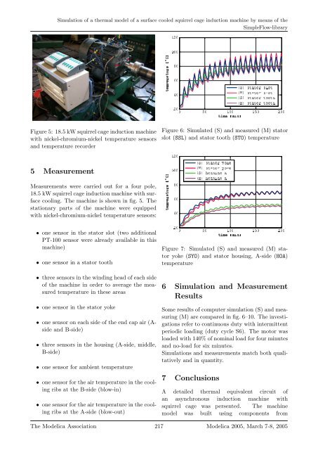
Figure 5: 18.5 kW <strong>squirrel</strong> <strong>cage</strong> induction machine<br />
with nickel-chromium-nickel temperature sensors<br />
and temperature recorder<br />
5 Measurement<br />
Measurements were carried out for a four pole,<br />
18.5 kW <strong>squirrel</strong> <strong>cage</strong> induction machine with <strong>surface</strong><br />
cooling. The machine is shown in fig. 5. The<br />
stationary parts <strong>of</strong> the machine were equipped<br />
with nickel-chromium-nickel temperature sensors:<br />
• one sensor in the stator slot (two additional<br />
PT-100 sensor were already available in this<br />
machine)<br />
• one sensor in a stator tooth<br />
• three sensors in the winding head <strong>of</strong> each side<br />
<strong>of</strong> the machine in order to average the measured<br />
temperature in these areas<br />
• one sensor in the stator yoke<br />
• one sensor on each side <strong>of</strong> the end cap air (Aside<br />
and B-side)<br />
• three sensors in the housing (A-side, middle,<br />
B-side)<br />
• one sensor for ambient temperature<br />
• one sensor for the air temperature in the cooling<br />
ribs at the B-side (blow-in)<br />
• one sensor for the air temperature in the cooling<br />
ribs at the A-side (blow-out)<br />
<br />
<br />
<br />
<br />
<br />
<br />
<br />
<br />
<br />
<br />
<br />
<br />
<br />
<br />
<br />
<br />
<br />
<br />
<br />
<br />
Figure 6: Simulated (S) and measured (M) stator<br />
slot (SSL) and stator tooth (STO) temperature<br />
<br />
<br />
<br />
<br />
<br />
<br />
<br />
<br />
<br />
<br />
<br />
<br />
<br />
<br />
<br />
<br />
<br />
<br />
<br />
<br />
Figure 7: Simulated (S) and measured (M) stator<br />
yoke (SYO) and stator housing, A-side (HOA)<br />
temperature<br />
6 <strong>Simulation</strong> and Measurement<br />
Results<br />
Some results <strong>of</strong> computer simulation (S) and measuring<br />
(M) are compared in fig. 6–10. The investigations<br />
refer to continuous duty with intermittent<br />
periodic loading (duty cycle S6). The motor was<br />
loaded with 140% <strong>of</strong> nominal load for four minutes<br />
and no-load for six minutes.<br />
<strong>Simulation</strong>s and measurements match both qualitatively<br />
and in quantity.<br />
7 Conclusions<br />
A detailed <strong>thermal</strong> equivalent circuit <strong>of</strong><br />
an asynchronous induction machine with<br />
<strong>squirrel</strong> <strong>cage</strong> was persented. The machine<br />
<strong>model</strong> was built using components from<br />
The Modelica Association 217 Modelica 2005, March 7-8, 2005


