75642001.pdf - Berker
75642001.pdf - Berker
75642001.pdf - Berker

You also want an ePaper? Increase the reach of your titles
YUMPU automatically turns print PDFs into web optimized ePapers that Google loves.
Universal interface comfort 4gang<br />
flush-mounted<br />
75642001<br />
Functional description:<br />
Technische<br />
Dokumentation<br />
The 2-channel push button interface has 2 independent channels which – depending on parameterization<br />
– can be used as inputs or alternatively as outputs. The push button interface can therefore be used to<br />
poll its inputs for the switching state of up to 2 potential-free push buttons/switches with a common<br />
reference potential and send the corresponding telegrams to the instabus. These may be telegrams for<br />
switching or dimming, shutter/blind control or value transmitter applications (dimming value transmitter,<br />
light-scene extension, temperature or brightness value transmitter). Moreover, 2 switching event counters<br />
or 1 pulse counter (only channel 1) are available.<br />
Channels 1 and 2 can be used alternatively as independent outputs for controlling up to two LEDs. To<br />
increase the output current (cf. Technical Data), the channels can also be connected in parallel if they are<br />
parameterized alike. The outputs are short-circuit-proof and protected against overloading and false<br />
polarity.<br />
Connecting 230 V signals or other external voltages to the inputs is not permitted.<br />
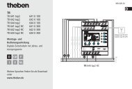
Layout: Dimensions: Controls:<br />
- +<br />
A B C<br />
A1/E1<br />
GN<br />
A2/E2<br />
YE<br />
com<br />
GY<br />
Width (W): 44 mm<br />
Height (H): 16 mm<br />
Depth (D): 29 mm<br />
A Programming button<br />
B Programming LED (red)<br />
C Connecting wires<br />
green: channel 1<br />
yellow: channel 2<br />
grey: reference<br />
potential (com)<br />
Technical Data<br />
Type of protection: IP 20<br />
Safety class: III<br />
Mark of approval: KNX / EIB<br />
Ambient temperature: -5 °C ... +45 °C<br />
Storage / transport temperature: -25 °C ... +70 °C (storage above +45 °C results in shorter<br />
lifetime)<br />
Mounting position: any<br />
Minimum spacings: none<br />
Type of fastening: e.g. placing into deep flush-mounting box (∅ 60 mm x 60 mm)<br />
Instabus EIB supply<br />
Voltage: 21 - 32 V DC SELV<br />
Power consumption: typ. 150 mW<br />
Connection: bus connecting and branching terminal<br />
External supply ---<br />
Response to voltage failure<br />
Bus voltage only: no response (outputs switching off)<br />
Mains voltage only: ---<br />
Bus and mains voltages: ---<br />
Response to return of voltage<br />
Bus voltage only: the response of the inputs and the outputs can be parameterized<br />
(cf. "Response to return of bus voltage").<br />
Mains voltage only: ---<br />
Bus and mains voltages: ---<br />
© Gebr.<strong>Berker</strong> 2005 Version: 11.05.2005 Page: 1 / 41<br />
(Subject to prior change) 75642001.doc Part 4
Universal interface comfort 4gang<br />
flush-mounted<br />
75642001<br />
Technische<br />
Dokumentation<br />
Inputs:<br />
Number: up to 2 (depending on parameterization: channel 1 to 4)<br />
Line length: 25 cm prefabricated, extendable to 5 m max.<br />
Scanning voltage: continuous signal<br />
Loop resistance: max. 2 kOhm for safe detection of a "1" signal (rising edge)<br />
Outputs:<br />
Number: up to 2 (depending on parameterization: channel 1 and/or 2)<br />
Line length: 25 cm prefabricated, extendable to 5 m max<br />
Output current: max. 0.8 mA per output channel<br />
(at 1.5 V; typ. for red low-current LED)<br />
For parallel connection, the maximum total output current<br />
increases to 1.6 mA. In the event of parallel connection, outputs<br />
1 and 2 must be parameterized exactly alike (none of the output<br />
signals flashing)<br />
The outputs are short-circuit-proof, protected against overloading<br />
and false polarity.<br />
Output voltage: typ. 1.5 V (e.g. red low-current LED)<br />
(5 V with outputs open circuit)<br />
Connecting diagram: Terminals:<br />
Channel 1 (green)<br />
Channel 2 (yellow)<br />
Reference potential (grey)<br />
Ch1<br />
Ch2<br />
Universal interface used as 2 inputs<br />
© Gebr.<strong>Berker</strong> 2005 Version: 11.05.2005 Page: 2 / 41<br />
(Subject to prior change) 75642001.doc Part 4<br />
Channel 1 (green)<br />
Channel 2 (yellow)<br />
Reference potential (grey)<br />
Ch1<br />
Ch2<br />
Example of universal interface used with<br />
1 input and 1 output<br />
Important: - Connect only potential-free switches or push buttons to the inputs.<br />
- To obtain sufficient signalling brightness, it is recommended to connect "low-current LEDs"<br />
to the outputs.<br />
Hardware information<br />
• To avoid EMC-related interference, the lines to the inputs should not be laid parallel to lines carrying<br />
mains voltage.<br />
• Connecting 230 V signals or other external voltages to the inputs is not permitted.<br />
• The voltage potentials on the lines connecting the contacts or the LEDs are not electrically isolated from<br />
the bus voltage.
Universal interface comfort 4gang<br />
flush-mounted<br />
75642001<br />
Software description<br />
ETS search path:<br />
Technische<br />
Dokumentation<br />
Inputs / Binary input 2gang / Universal interface comfort 4gang flush-mounted<br />
ETS symbol:<br />
PEI type<br />
Applications:<br />
00 Hex 0 Dez No adapter used<br />
Nr. Short description: Name: Version:<br />
1 2 inputs or alternatively<br />
1 input, 1 output<br />
2 outputs<br />
2 inputs, 2 outputs 705801 0.1<br />
Application: 1. 2 inputs, 2 outputs 705801<br />
Executable from mask version: 1.1<br />
Number of addresses (max): 26 dynamic table handling Yes No <br />
Number of assignments (max): 27 maximum length of table 53<br />
Communication objects: 6<br />
Objects for binary inputs:<br />
Function: No function (for all 2 inputs 2 )<br />
No further input objects!<br />
Function: Binary input / "Switching" (for all 2 inputs 2 )<br />
Object Function Name Type Flag<br />
0 - 3 Switching object X.1 (X = 1 - 2) Input 1 – Input 2 1 bit<br />
1<br />
C, W, T, (R)<br />
1<br />
8 - 11 Switching object X.2 (X = 1 - 2) Input 1 – Input 2 1 bit C, W, T, (R)<br />
Function: Binary input / "Dimming" (for all 2 inputs 2 )<br />
Object Function Name Type Flag<br />
0 - 3 Switching Input 1 – Input 2 1 bit<br />
1<br />
C, W, T, (R)<br />
1<br />
8 - 11 Dimming Input 1 – Input 2 4 bit C, T, (R)<br />
Function: Binary input / "Shutter/blind" (for all 2 inputs 2 )<br />
Object Function Name Type Flag<br />
0 - 3 Step operation Input 1 – Input 2 1 bit<br />
1<br />
C, W, (R)<br />
1<br />
8 - 11 Move operation Input 1 – Input 2 1 bit C, T, (R)<br />
Function: Binary input / "Value transmitter" (Function: dimming value transmitter for all 2 inputs 2 )<br />
Object Function Name Type Flag<br />
0 - 3 Value Input 1 – Input 2 1 byte<br />
1<br />
C, W, (R)<br />
Function: Binary input / "Value transmitter" (Function: Light-scene extension with / without memory<br />
function for all 2 inputs 2 )<br />
Object Function Name Type Flag<br />
0 - 3 Light-scene extension Input 1 – Input 2 1 byte<br />
1<br />
C, W, (R)<br />
Function: Binary input / "Value transmitter" (Function: Temperature value transmitter for all 2 inputs 2 )<br />
Object Function Name Type Flag<br />
8 - 11 Temperature value Input 1 – Input 2 2 byte<br />
1<br />
C, W, (R)<br />
Function: Binary input / "Value transmitter" (Function: Brightness value transmitter for all 2 inputs 2 )<br />
Object Function Name Type Flag<br />
8 - 11 Brightness value Input 1 – Input 2 2 byte<br />
1<br />
C, W, (R)<br />
© Gebr.<strong>Berker</strong> 2005 Version: 11.05.2005 Page: 3 / 41<br />
(Subject to prior change) 75642001.doc Part 4<br />
n
Universal interface comfort 4gang<br />
flush-mounted<br />
75642001<br />
Technische<br />
Dokumentation<br />
1 : Objects marked (R) permit read-out of the object status (set R flag).<br />
2 : The "No function", "Switching", "Dimming", "Shutter/blind" and "Value transmitter" functions can be<br />
selected per input. The names of the communication objects and the object table (dynamic object<br />
structure) will change accordingly.<br />
Function: Binary input / "Pulse counter" (for input 1 3 )<br />
Object Function Name Type Flag<br />
1 Sync signal pulse counter 1 Input 2 1 bit C, W, T, (R) 1<br />
8 Pulse counter 1 status Input 1 2 byte C, T, (R) 1<br />
Function: Binary input / "Switching event counter" (for inputs 1 and 2 3 )<br />
Object Function Name Type Flag<br />
0 Switching event counter Input 1 1 bit C, W, T, (R) 1<br />
1 Switching event counter Input 2 1 bit C, W, T, (R) 1<br />
8 Switching event counter Input 1 2 byte C, T, (R) 1<br />
9 Switching event counter Input 2 2 byte C, T, (R) 1<br />
Function: Disabling (for all 2 inputs 4 )<br />
Object Function Name Type Flag<br />
16 - 17 Disabling Input 1 – Input 2 1 bit<br />
1<br />
C, T, (R)<br />
Objects for (LED) outputs:<br />
Function: Output (for all 2 outputs)<br />
Object Function Name Type Flag<br />
0 - 1 Switching Output 1 - 2 1 bit<br />
1<br />
C, W, (R)<br />
Function: Additional function for outputs = "Logic-operation object" (for all 2 outputs)<br />
Object Function Name Type Flag<br />
8 - 9 Logic operation Output 1 - 2 1 bit<br />
1<br />
C, W, (R)<br />
Function: Additional function for outputs = "Disabling object" (for all 2 outputs 5 )<br />
Object Function Name Type Flag<br />
8 - 9 Disabling Output 1 - 2 1 bit<br />
1<br />
C, W, (R)<br />
Function: Additional function for outputs = "Forced guidance object" (for all 2 outputs 5 )<br />
Object Function Name Type Flag<br />
8 - 9 Forced guidance Output 1 - 2 2 bit<br />
1<br />
C, W, (R)<br />
Function: Revertive signal (feedback) for outputs (for all 2 outputs 5 )<br />
Object Function Name Type Flag<br />
16 - 17 Revertive signal (feedback) Output 1 - 2 1 bit<br />
1<br />
C, W, (R)<br />
1<br />
: For objects marked (R), the current object status can be read out (set R flag).<br />
3<br />
: The "pulse counter" and "switching event counter" functions can only be parameterized for inputs 1 and<br />
2.<br />
In the "pulse counter" function parameterized for input 1 (2), input 3 (4) will be reserved for the sync<br />
signal. For this reason, input 3 (4) must be parameterized as "Pulse counter / Sync input".<br />
4<br />
: If the inputs have been parameterized for "No function", "Pulse counter" or "Switching counter", no<br />
Disabling function will be possible.<br />
5<br />
: Only channels 1 and 2 can be parameterized as outputs. For this reason, the feedback objects and the<br />
additional functions can be selected for these outputs only.<br />
© Gebr.<strong>Berker</strong> 2005 Version: 11.05.2005 Page: 4 / 41<br />
(Subject to prior change) 75642001.doc Part 4
Universal interface comfort 4gang<br />
flush-mounted<br />
75642001<br />
Object description<br />
Technische<br />
Dokumentation<br />
Objects for binary inputs:<br />
0 – 1 Switching object X.1: 1-bit object for transmitting switching telegrams (ON, OFF)<br />
(1 st switching object)<br />
8 – 9 Switching object X.2: 1-bit object for transmitting switching telegrams (ON, OFF)<br />
(2 nd switching object)<br />
8 – 9 Switching: 1- bit object for transmitting switching telegrams (ON, OFF) for<br />
the dimming function<br />
8 – 9 Dimming: 4-bit object for relative brightness variation between 0 and 100 %<br />
0 – 1 Short-time operation: 1-bit object for STEP operation of a shutter<br />
8 – 9 Long-time operation: 1-bit object for MOVE operation of a shutter<br />
0 – 1 Value: 1-byte object for transmitting value telegrams (0 - 255)<br />
0 – 1 Light-scene extension 1-byte object for recalling and storing light-scenes (1 - 64)<br />
8 – 9 Temperature value: 2-byte object for adjusting a fixed temperature value (0 - 40 °C)<br />
8 – 9 Brightness value: 2-byte object for adjusting a fixed brightness value (0 - 1500 lux)<br />
1 Sync signal<br />
pulse counter X:<br />
1-bit object for transmitting switching telegrams depending on the<br />
sync signal<br />
8 Pulse counter X status: 2-byte object for transmitting the pulse counter status<br />
0 / 1 Switching event counter: 1-bit object for transmitting switching telegrams depending on<br />
counter status<br />
8 / 9 Switching event counter: 2-byte object for transmitting the counter status<br />
16 – 17 Disabling: 1-bit object for disabling individual binary inputs<br />
(polarity parameterizable)<br />
Objects for (LED) outputs:<br />
0 – 1 Switching: 1-bit object for controlling an (LED) output<br />
8 – 9 Logic operation: 1-bit object for logic-operation control of an (LED ) output<br />
(ON: Logic-operation input "1" / OFF: Logic-operation input "0")<br />
8 – 9 Disabling: 1-bit object for disabling an (LED) output<br />
(polarity parameterizable)<br />
8 – 9 Forced guidance: 2-bit object for prioritary forced guidance (priority-position control)<br />
16 – 17 Revertive signal<br />
(feedback):<br />
of an (LED ) output<br />
1-bit object for switching status feedback of an (LED ) output<br />
(feedback invertible)<br />
© Gebr.<strong>Berker</strong> 2005 Version: 11.05.2005 Page: 5 / 41<br />
(Subject to prior change) 75642001.doc Part 4
Universal interface comfort 4gang<br />
flush-mounted<br />
75642001<br />
Scope of functions<br />
Binary inputs:<br />
Technische<br />
Dokumentation<br />
General<br />
• "Switching", "dimming", "shutter/blind", "value transmitter" and "switching event counter" functions<br />
freely assignable to the max. 2 inputs<br />
• "Pulse counter" function freely assignable to input 1<br />
In the "pulse counter" function parameterized for input 1, input 2 will be reserved for the sync signal.<br />
For this reason, input 2 must be parameterized as "Pulse counter / Sync input".<br />
• Disabling object for disabling of individual inputs (polarity of disabling object presettable)<br />
• Delay on return of bus voltage and debouncing time centrally adjustable<br />
• Response to bus voltage return separately parameterizable for each input<br />
• Telegram rate limitation generally parameterizable for all inputs<br />
Switching function<br />
• Two independent switching objects available for each input (switching commands individually<br />
parameterizable)<br />
• Command for rising and falling edge individually adjustable (ON, OFF, TOGGLE, no reaction).<br />
• Independent cyclical transmission of switching objects depending on edge or on object value<br />
selectable.<br />
Dimming function<br />
• Single-sided and double-sided actuation<br />
• Time between dimming and switching and dimming step width presettable<br />
• Telegram repetition and stop telegram transmission possible<br />
Shutter/blind function<br />
• Command for rising edge adjustable (no function, UP, DOWN, TOGGLE)<br />
• Operating concept parameterizable ("step - move – step" resp. "move – step")<br />
• Time between STEP and MOVE operation presettable (only with "step - move - step")<br />
• Slat adjustment time presettable (time during which a "Move" command can be terminated by<br />
releasing a push button on the input)<br />
Value transmitter and light-scene extension functions<br />
• Edge (push button as n.o. contact, push button as n.c. contact, switch) and value for edge<br />
parameterizable<br />
• Value change in push button mode possible with long press on the button for value transmitter<br />
• In light-scene extension with storage function, a light-scene can be stored withous preceding recall<br />
Temperature and brightness value transmitter functions<br />
• Edge (push button as n.o. contact, push button as n.c. contact, switch) and value for edge<br />
parameterizable<br />
• Value change in push button mode possible with long press on the button<br />
Pulse counter function<br />
• Edge for pulse count and time interval for counter status transmission parameterizable<br />
• Edge of sync signal for resetting of counter status and switching telegram on arrival of sync signal<br />
depending on edge presettable<br />
Switching event counter function<br />
• Edge for counting of signal at input and maximum reading of counter selectable<br />
• Step width for counter status output and command (no telegram, ON, OFF, TOGGLE) on reaching the<br />
maximum reading of counter parametrizable<br />
© Gebr.<strong>Berker</strong> 2005 Version: 11.05.2005 Page: 6 / 41<br />
(Subject to prior change) 75642001.doc Part 4
Universal interface comfort 4gang<br />
flush-mounted<br />
75642001<br />
Scope of functions (continued)<br />
Outputs:<br />
Technische<br />
Dokumentation<br />
• Independent switching of max. 2 outputs<br />
• Outputs parameterizable as n.o. contact (ON: output supplies current / OFF: output supplies no current)<br />
or as n.c. contact (ON: output supplies no current / OFF: output supplies current)<br />
• Preferred state on return of bus voltage presettable<br />
• For each output additional revertive signal (feedback) and additional function possible:<br />
Presettable additional functions: - logic-operation function with 3 logic parameters<br />
- disabling function with presettable disabling behaviour of the relays<br />
- forced guidance function to fix the priority of arriving switching teleg.<br />
• Revertive signal (feedback) object invertible<br />
• Delay on return of bus voltage centrally presettable<br />
• Switch-on delay and/or switch-off delay or timer function separately presettable for each output<br />
• Output signal as flashing signal (flashing frequency parameterizable in 3 steps)<br />
© Gebr.<strong>Berker</strong> 2005 Version: 11.05.2005 Page: 7 / 41<br />
(Subject to prior change) 75642001.doc Part 4
Universal interface comfort 4gang<br />
flush-mounted<br />
75642001<br />
Functional description<br />
Functional description of binary inputs<br />
Value transmitter by long key-press<br />
Technische<br />
Dokumentation<br />
In the even of value transmitter parameterization (value transmitter, temperature value transmitter or<br />
brightness value transmitter), the value to be transmitted can be changed by means of a long key-press (><br />
5 s) if the value is to be transmitted on the rising or the falling edge. In this case, the programmed value is<br />
increased by the parameterized step width and transmitted. After releasing of the input contact, the value<br />
last transmitted remains stored. On the next long key-press, the direction of value change is reversed.<br />
Example for dimming value transmitter 1 byte:<br />
value (0...255) 17<br />
step width (1...10) 5<br />
edge at input<br />
bus<br />
telegram<br />
Important:<br />
< 5 s<br />
5 s<br />
value change<br />
value variation direction change<br />
value change<br />
value = 17 17 17 12 7 2 0 0 0 2 7 12 17<br />
time between<br />
two telegrams<br />
no further value change<br />
minimum value reached<br />
- During value change there is no overrun and no underrun. When the maximum (255) resp. the minimum<br />
(0) value is reached, no more telegrams are transmitted.<br />
- To ensure that the concerned lighting switches off or on with the max. value during value change, the<br />
limit values (values "0" resp. "255") are always transmitted when the limits of the change range are<br />
reached. This is also the case when the parameterized step width does take these values directly into<br />
account (cf. example above: step width = 5; value "2" is transmitted, thereafter value "0").<br />
To ensure that the original starting value can be set again during a new change (change of variation<br />
direction), the first value jump will not correspond to the preset step width (cf. example above: step width<br />
= 5; value "0" is transmitted, thereafter values "2", "7" etc.).<br />
- When values are changed, the newly set values are stored in the RAM.<br />
After a bus voltage failure or a bus reset, the changed values will be replaced by the values originally<br />
parameterized in the ETS.<br />
© Gebr.<strong>Berker</strong> 2005 Version: 11.05.2005 Page: 8 / 41<br />
(Subject to prior change) 75642001.doc Part 4<br />
> 5 s<br />
time<br />
time
Universal interface comfort 4gang<br />
flush-mounted<br />
75642001<br />
Light-scene extension with / without storage function<br />
Technische<br />
Dokumentation<br />
In a parameterization as light-scene extension without memory function it is possible to recall a lightscene.<br />
In case of a rising edge, a falling edge or a rising and falling edge, the parameterized light-scene<br />
number is transmitted immediately.<br />
In a parameterization as light-scene extension with memory function it is possible to generate a storage<br />
telegram depending on the light-scene to be transmitted. A long actuation of the n.o. contact (rising edge)<br />
or of the n.c. contact (falling edge) causes the corresponding storage telegram to be transmitted. In this<br />
case, the time for a long press is parameterizable (however not below 5 s). After a short press < 1 s, the<br />
parameterized light-scene number (without storage telegram) is transmitted. If the actuation is longer than<br />
1 s, but shorter than 5 s, no telegram will be transmitted. In addition, it is possible to transmit only a<br />
storage telegram with preceding light-scene recall. In this case, the "Storage function only" parameter<br />
must be set to "YES".<br />
Examples for light-scene extension with storage function:<br />
1.)<br />
1.) storage function only = NO<br />
2.) storage function only = YES<br />
edge at input<br />
bus<br />
telegram<br />
light-sene<br />
recall<br />
2.) bus<br />
telegram<br />
light-scene<br />
storage<br />
storage<br />
< 1 s 1 s to 3 s<br />
5 s<br />
light-scene<br />
recall<br />
light-scene<br />
storage<br />
storage function only = NO:<br />
light-scene<br />
storage<br />
light-scene<br />
storage<br />
undefined input<br />
no telegram<br />
light-scene<br />
storage<br />
If a rising or a falling edge is detected at the input (depending on parametrization), the timer is started. If<br />
the key is released within the first second, the corresponding light-scene is recalled immediately. If the key<br />
is pressed longer, the storage telegram is transmitted after 5 s.<br />
storage function only = YES:<br />
The storage telegram is transmitted immediately after detection of the corresponding edge.<br />
© Gebr.<strong>Berker</strong> 2005 Version: 11.05.2005 Page: 9 / 41<br />
(Subject to prior change) 75642001.doc Part 4<br />
time<br />
time<br />
time
Universal interface comfort 4gang<br />
flush-mounted<br />
75642001<br />
Pulse counter<br />
Technische<br />
Dokumentation<br />
The pulse counter can only be parameterized for input 1. In this case, input 2 is reserved for the sync<br />
signal. For this reason, input 2 must be parameterized as "pulse counter/sync input".<br />
If channel 1 is selected as output, it cannot be assigned any pulse counting function.<br />
Pulse counter 1 has a resolution of 16 bits so that counts between 0 and 65535 are possible. The current<br />
counter status can be read out at object 8 by setting the R flag.<br />
The counting pulse is applied to input 1. After the parameterized interval time has elapsed, the counter<br />
status will be taken over and sent as object value of the 2-byte "count" object (object 8). The 2-byte pulse<br />
counter will then be internally reset during the next time interval.<br />
The current counter status in the count object can only be read out (set R flag) after a new edge at the<br />
input or after the newly started time interval has elapsed.<br />
In addition, the counter status and the interval time can be reset by a sync signal at input 2. Switching<br />
telegrams (no telegram, ON, OFF, TOGGLE) can moreover be transmitted depending on the sync signal<br />
edge. The output value can be assigned to the edge. The edge assignment for resetting of the counter<br />
status can be parameterized independent of the output value.<br />
input 1 / 2<br />
input 3 / 4<br />
output<br />
depending<br />
on edge<br />
The pulse counter cannot be disablingd.<br />
PULSE COUNTER<br />
16-bit counter<br />
© Gebr.<strong>Berker</strong> 2005 Version: 11.05.2005 Page: 10 / 41<br />
(Subject to prior change) 75642001.doc Part 4<br />
Reset<br />
timer<br />
Reset<br />
object 8 / 9<br />
object 2 / 3<br />
The counter status is stored in the RAM. After a bus voltage failure or a bus reset, the value is deleted<br />
("0").<br />
instabus
Universal interface comfort 4gang<br />
flush-mounted<br />
75642001<br />
Switching event counter<br />
Technische<br />
Dokumentation<br />
The switching event counters can only be parameterized for inputs 1 or 2. If channels 1 or 2 are defined as<br />
outputs, no switching event counter functions can be implemented for these channels.<br />
The switching event counters 1 and 2 run independently of each other and have a resolution of 16 bits so<br />
that counts between 0 and 65535 are possible. The current counter status can be read out at objects 8 or<br />
9 by setting the R flag.<br />
The counting pulse is applied to input 1 or 2, respectively. After the count has reached the parameterized<br />
default value, the counter status is taken over into the the 2-byte object 8 resp. 9 and transmitted. In this<br />
case, a parameterizable signal value (1-bit-object "0" resp."1") can be output. After the transmission, the<br />
16-bit counter is automatically reset internally. The current count in the counter status objects can only be<br />
read out (set R flag) after a new edge at the input.<br />
The counter status is additionally transmitted cyclically after a predefined number of counting pulses<br />
(1...255).<br />
input 1 / 2 16-bit counter<br />
The switching event counter cannot be disablingd.<br />
SWITCHING EVENT COUNTER<br />
16-bit comparator<br />
maximum count<br />
8-bit counter<br />
8-bit comparator<br />
step width<br />
object 8 / 9<br />
object 0 / 1<br />
The counts are stored in the RAM. After a bus voltage failure or a bus reset, the value is deleted ("0").<br />
© Gebr.<strong>Berker</strong> 2005 Version: 11.05.2005 Page: 11 / 41<br />
(Subject to prior change) 75642001.doc Part 4<br />
Reset<br />
Reset<br />
instabus
Universal interface comfort 4gang<br />
flush-mounted<br />
75642001<br />
Response to return of bus voltage<br />
Technische<br />
Dokumentation<br />
It is possible to define separately for each input whether a reaction or what kind of reaction is to take place<br />
on return of bus voltage so that a defined telegram can be transmitted to the bus depending on the input<br />
signal or by forced control.<br />
The defined reaction takes place only after the parameterized "Delay after bus voltage return" has<br />
elapsed.<br />
While the delay is active, any edges or signals present at the inputs are not evaluated and discarded. The<br />
delay is generally parameterized for all inputs and also for the outputs.<br />
It is possible to parameterize a general telegram rate limitation. In this case, no telegram is transmitted<br />
within the first 17 s after bus voltage return.<br />
It should be noted that the parameterized "Delay on return of bus voltage" is active also during this time<br />
and that the parameterized reaction on bus voltage return is not executed if the delay lies within the first 17<br />
seconds.<br />
Disabling function<br />
Each input can be independently configured for a certain reaction at the beginning or at the end of<br />
disabling. It is also possible to parameterize the input for "No reaction". Only in this case will dimming or<br />
shutter control procedures or value changes in progress before activation of the disabling function<br />
continue to be executed until the end when disabling is active. In all other cases, the parameterized<br />
command will be transmitted immediately at the beginning of disabling. During an active disabling, edges<br />
or signals at the corresponding inputs are not evaluated.<br />
Updates on disabling objects (disabling or enable) will always lead to the transmission of the<br />
corresponding command parameterized for "the beginning resp. the end of disabling".<br />
During an active disabling, no cyclical transmission takes place to the disablingd input.<br />
If cyclical transmission did take place before activation of the disabling function, no cyclical transmission<br />
will take place anymore at the end of disabling when "No reaction" is parameterized. In this case, the<br />
object value will again be transmitted cyclically only after an update on the switching object. In all other<br />
cases, the object value will again be transmitted cyclically after the end of disabling.<br />
Cyclical transmission<br />
The object value transmitted is always the object value internally or externally followed up in the switching<br />
objects. For this reason, the object value is transmitted cyclically even if "No reaction" is assigned to a<br />
rising or a falling edge.<br />
Cyclical transmission takes place also directly after the return of bus voltage, if the parameterized value of<br />
the telegram after bus voltage return corresponds to the object value parameterization for cyclical<br />
transmission. If telegram rate limitation is enabled, cyclical transmission will take place at the earliest after<br />
17 seconds.<br />
During an active disabling, no cyclical transmission takes place via the disablingd input.<br />
© Gebr.<strong>Berker</strong> 2005 Version: 11.05.2005 Page: 12 / 41<br />
(Subject to prior change) 75642001.doc Part 4
Universal interface comfort 4gang<br />
flush-mounted<br />
75642001<br />
Functional description for LED outputs<br />
Response to return of bus voltage<br />
Technische<br />
Dokumentation<br />
The preferred state of a switching output on return of bus voltage can be defined.<br />
In this way, the switching output can be 'energized' (setting: "Close contact" / LED on) or 'deenergized'<br />
(setting: "Open contact" / LED off). The "Mode" parameter (normally open or normally closed) is irrelevant<br />
in this case.<br />
The switching state that was active before bus voltage failure (setting: "Value before bus voltage failure")<br />
can moreover be followed up. Timer or other activated logic-operation functions which may have been<br />
started before bus voltage failure will not be accounted for.<br />
The switching state set after return of bus voltage will be followed up only in the feedback object.<br />
The defined response to bus voltage return will be triggered only after the parameterized "Delay on bus<br />
voltage return" has elapsed. Within the delay period, the outputs show no reaction. Updates of the<br />
switching objects via the bus during the delay period will be stored and executed only after the end of the<br />
delay.<br />
It is possible to parameterize a general telegram rate limitation. In this case, no telegram will be<br />
transmitted via the feedback objects within the first 17 s after bus voltage return.<br />
The switching outputs can nevertheless be actuated via the switching objects as soon as the "Delay on<br />
bus bus voltage return" has elapsed.<br />
In the event of bus voltage failure, the outputs will always switch off (LED off).<br />
A disabling function or a priority position activated before bus voltage failure is always deactivated after<br />
return of bus voltage.<br />
Revertive signal (feedback) object<br />
When the switching state of an output changes, the current switching state is transmitted to the bus via<br />
the corresponding revertive signal (feedback) object.<br />
The revertive signal (feedback) object value is updated also after return of bus voltage when the<br />
parameterized delay period has elapsed and is actively transmitted to the bus. With telegram rate<br />
limitation being enabled, no telegram will be transmitted via the revertive signal (feedback) objects within<br />
the first 17 s. The revertive signal (feedback) signal is stored and then executed after the 17 s delay has<br />
elapsed.<br />
It may be possible to read out the object status by means of a display software (set R flag!).<br />
The switching status set after return of bus voltage will only be followed up in the revertive signal<br />
(feedback) object so that the switching object is not updated.<br />
Flashing output signals<br />
If desired, the output signal of a switching output may be in a flashing mode when the LED is on (contact<br />
closed). The flashing function can be activated separately for both switching outputs.<br />
The flashing frequency can be preset in three steps:<br />
- fast (approx. 9 Hz)<br />
- medium (approx. 4 Hz)<br />
- slow (approx. 1 Hz).<br />
Synchronous flashing of both outputs cannot be guaranteed.<br />
To increase the total output current (cf. technical data), both switching outputs can be connected in<br />
parallel, if they have the same parameterization. When connected in parallel in this way, the output<br />
channels cannot be operated in the flashing mode.<br />
© Gebr.<strong>Berker</strong> 2005 Version: 11.05.2005 Page: 13 / 41<br />
(Subject to prior change) 75642001.doc Part 4
Universal interface comfort 4gang<br />
flush-mounted<br />
75642001<br />
Additional functions<br />
Forced guidance object:<br />
Technische<br />
Dokumentation<br />
The forced guidance (priority-position) object can be used to force a switching output by means of 2-bit<br />
telegrams independently of the switching object separately into a switching position. The "Mode"<br />
parameter remains effective in this case, too. The value of the 2-bit telegram must have the following<br />
sysntax:<br />
The first bit (bit 0) of the priority-position obj. Bit 1 Bit 0 Function<br />
determines the switching state to be forced on 0 x Priority not active, ´switching´ object<br />
the output. The second bit (bit 1) of the 0 x Priority not active, ´switching´ object<br />
priority-position object enables 1 0 Priority active switching off<br />
the priority-position mode. 1 1 Priority active switching on<br />
When the forced guidance (priority-position) mode is active (priority), any incoming switching telegrams<br />
will still be evaluated internally. When the forced guidance (priority-position) mode is thereafter no longer<br />
active (priority), the current internal switching state will be set depending on the value of the switching<br />
object.<br />
A forced guidance (priority-position) mode that was active before bus voltage failure will always be inactive<br />
after return of bus voltage.<br />
Logic-operation object:<br />
If the logic-operation object has been parameterized, it is possible to implement a logic operation on the<br />
switching object of the corresponding output. In this case, the object values of the logic-operation object<br />
and of the switching object are combined by means of the "AND" / "OR" / "AND with feedback" operations.<br />
Depending on the result of these logic operations, the output will be activated or not.<br />
AND with feedback:<br />
With a logic-operation object = "0" the output is always "0" (logic AND). In this case, the feedback of<br />
the output to the switching object, resets the switching object when it is being set.<br />
Only if the logic-operation object = "1", can the output pass to logic state "1" after a newly received "1"<br />
on the switching object.<br />
Switching<br />
Logic-operation<br />
Feedback<br />
© Gebr.<strong>Berker</strong> 2005 Version: 11.05.2005 Page: 14 / 41<br />
(Subject to prior change) 75642001.doc Part 4<br />
&<br />
Output
Universal interface comfort 4gang<br />
flush-mounted<br />
75642001<br />
Disabling object:<br />
Technische<br />
Dokumentation<br />
If the disabling object has been parameterized, an assigned output can be locked in a parameterizable<br />
switching position after reception of a disabling telegram. The polarity of the disabling object can be<br />
preselected.<br />
When the disabling function is activated or deactivated, the response of the output can be predefined for<br />
both cases. The output can either switch on or switch off. The "Mode" parameter must be taken into<br />
account in this case.<br />
Examples:<br />
Mode = "n.o. contact", command "Switch off" output supplying no current,<br />
Mode = " n.o. contact", command "Switch on" output supplying current,<br />
Mode = "n.c. contact", command "Switch off" output supplying current,<br />
Mode = "n.c. contact", command "Switch on" output supplying no current<br />
In the "No change" setting, the switching status before the disabling function or the switching status set by<br />
the disabling function is retained. During an active disabling function, telegrams received via the switching<br />
object will be discarded. A disabling function that was active before bus voltage failure will always be<br />
inactive after return of bus voltage.<br />
© Gebr.<strong>Berker</strong> 2005 Version: 11.05.2005 Page: 15 / 41<br />
(Subject to prior change) 75642001.doc Part 4
Universal interface comfort 4gang<br />
flush-mounted<br />
75642001<br />
Technische<br />
Dokumentation<br />
Parameters<br />
Description: Values: Comment:<br />
Function<br />
Function channel 1<br />
Channel 1:<br />
Output signal flashing?<br />
Binary input<br />
Output (LED max. 0.8 mA)<br />
YES<br />
NO<br />
Flashing frequency slow (approx. 1 Hz)<br />
medium (approx. 4 Hz)<br />
fast (approx. 9 Hz)<br />
Function channel 2 Binary input<br />
Output (LED max. 0.8 mA)<br />
Channel 2:<br />
Output signal flashing?<br />
YES<br />
NO<br />
Flashing frequency slow (approx. 1 Hz)<br />
medium (approx. 4 Hz)<br />
fast (approx. 9 Hz)<br />
Description: Values: Comment:<br />
General<br />
Delay on return of bus<br />
voltage<br />
Base<br />
Delay on return of bus<br />
voltage<br />
Factor (3...127)<br />
130 ms<br />
260 ms<br />
520 ms<br />
1 s<br />
2.1 s<br />
4.2 s<br />
8.4 s<br />
17 s<br />
34 s<br />
1.1 min<br />
2.2 min<br />
4.5 min<br />
9 min<br />
18 min<br />
35 min<br />
1.2 h<br />
Defines the function of the first channel.<br />
Defines whether the output signal of a<br />
switching output flashes or not.<br />
Only if "Function channel 1 = output"<br />
Defines the flashing frequency of the<br />
output signal.<br />
Only if "Channel 1: output signal flashing<br />
= YES"<br />
Defines the function of the second<br />
channel.<br />
Defines whether the output signal of a<br />
switching output flashes or not.<br />
Only if "Function channel 2 = output"<br />
Defines the flashing frequency of the<br />
output signal.<br />
Only if "Channel 2: output signal flashing<br />
= YES"<br />
After return of bus voltage, the application<br />
program of the push button interface can<br />
be disablingd for a defined period of time<br />
before the corresponding reactions take<br />
place.<br />
During this time, no signals present on<br />
the inputs will be evaluated and the<br />
switching outputs will not be activated<br />
either. Even a feedback signal cannot be<br />
expected before the delay has elapsed.<br />
Defines the time base of the delay period.<br />
Time = Base Factor<br />
3 to 127, 17 Defines the time factor of the delay<br />
period.<br />
Time = Base Factor<br />
Presetting: 1 s ·17 = 17 s<br />
© Gebr.<strong>Berker</strong> 2005 Version: 11.05.2005 Page: 16 / 41<br />
(Subject to prior change) 75642001.doc Part 4
Universal interface comfort 4gang<br />
flush-mounted<br />
75642001<br />
Debouncing time for binary<br />
inputs<br />
Factor (10...255) * 0.5 ms<br />
Telegram rate limitation<br />
Telegrams per 17 s 30<br />
60<br />
100<br />
127<br />
0 to 255, 60<br />
enabled<br />
disablingd<br />
Technische<br />
Dokumentation<br />
Description: Values: Comment:<br />
Input 1 (only if "Function channel 1 = binary input")<br />
Function channel 1<br />
Function of input 1 = "No function"<br />
No further parameters<br />
Function of input 1 = "Switching"<br />
Command on rising edge<br />
Switching object 1.1<br />
Command on falling edge<br />
Switching object 1.1<br />
Command on rising edge<br />
Switching object 1.2<br />
Command on falling edge<br />
Switching object 1.2<br />
No function<br />
Switching<br />
Dimming<br />
Shutter/blind<br />
Value transmitter<br />
Pulse counter<br />
Switching event counter<br />
No reaction<br />
ON<br />
OFF<br />
TOGGLE<br />
No reaction<br />
ON<br />
OFF<br />
TOGGLE<br />
No reaction<br />
ON<br />
OFF<br />
TOGGLE<br />
No reaction<br />
ON<br />
OFF<br />
TOGGLE<br />
Defines the software debouncing time in<br />
common for all binary inputs. A signal<br />
edge at the input will be evaluated with a<br />
delay corresponding to the time defined.<br />
Time = 0.5 ms Factor<br />
Presetting: 0.5 ms 20 = 10 ms<br />
The telegram rate limitation can be<br />
enabled or disablingd. When the<br />
telegram rate limitation is enabled, no<br />
telegrams will be transmitted in the first<br />
17 s after bus voltage return.<br />
When the telegram rate limitation is<br />
enabled, the maximum number of<br />
telegrams in 17 s can be preset here.<br />
Defines the function of input 1.<br />
Defines the command transmitted via<br />
switching object 1.1 on the rising edge.<br />
"TOGGLE" toggles the object value.<br />
Defines the command transmitted via<br />
switching object 1.1 on the falling edge.<br />
"TOGGLE" toggles the object value.<br />
Defines the command transmitted via<br />
switching object 1.2 on the rising edge.<br />
"TOGGLE" toggles the object value.<br />
Defines the command transmitted via<br />
switching object 1.2 on the falling edge.<br />
"TOGGLE" toggles the object value.<br />
© Gebr.<strong>Berker</strong> 2005 Version: 11.05.2005 Page: 17 / 41<br />
(Subject to prior change) 75642001.doc Part 4
Universal interface comfort 4gang<br />
flush-mounted<br />
75642001<br />
Response to bus voltage<br />
return<br />
Cyclical transmission?<br />
Time base for cyclical<br />
transmission<br />
Switching object 1.1<br />
Time base for cyclical<br />
transmission<br />
Switching object 1.2<br />
Time base for cyclical<br />
transmission<br />
Switching object 1.1 and<br />
1.2<br />
Factor (3...127)<br />
No reaction<br />
Transmit current input status<br />
Transmit ON telegram<br />
Transmit OFF telegram<br />
No cyclical transmission<br />
Repeat when ON<br />
Repeat when OFF<br />
Repeat when ON and OFF<br />
1 s<br />
2.1 s<br />
4.2 s<br />
8.4 s<br />
17 s<br />
34 s<br />
1.1 min<br />
34 s<br />
1 s<br />
2.1 s<br />
4.2 s<br />
8.4 s<br />
17 s<br />
34 s<br />
1.1 min<br />
34 s<br />
1.1 min<br />
2.2 min<br />
4.5 min<br />
9 min<br />
18 min<br />
35 min<br />
1.2 h<br />
1.1 min<br />
2.2 min<br />
4.5 min<br />
9 min<br />
18 min<br />
35 min<br />
1.2 h<br />
no cyclical<br />
transmission<br />
via switching<br />
object X.2<br />
Technische<br />
Dokumentation<br />
Permits defining the reaction that is to<br />
take place after return of bus voltage.<br />
The parameterized delay after return of<br />
bus voltage must have elapsed before<br />
the reaction defined will be executed.<br />
No reaction.<br />
The current input state corresponding to<br />
the parameterization for rising and falling<br />
edge is transmitted.<br />
Transmits an ON signal.<br />
Transmits an OFF signal.<br />
Cyclical transmission can be realized via<br />
the switching objects depending on the<br />
object value.<br />
No cyclical transmission.<br />
Cyclical transmission active when the<br />
object value is "ON".<br />
Cyclical transmission active when the<br />
object value is "OFF".<br />
Cyclical transmission always active<br />
independent of object value.<br />
Defines the time base for cyclical<br />
transmission via switching object 1.1.<br />
Time = Base • Factor<br />
Defines the time base for cyclical<br />
transmission via switching object 1.2.<br />
Cyclical transmission via switching object<br />
1.2 can be disabled when "No cyclical<br />
transmission via switching object X.2" is<br />
selected.<br />
Time = Base • Factor<br />
3 to 127, 60 Defines the time base for cyclical<br />
transmission via both switching objects.<br />
Time = Base • Factor<br />
Presetting: 1 s ⋅ 60 = 60 s<br />
© Gebr.<strong>Berker</strong> 2005 Version: 11.05.2005 Page: 18 / 41<br />
(Subject to prior change) 75642001.doc Part 4
Universal interface comfort 4gang<br />
flush-mounted<br />
75642001<br />
Technische<br />
Dokumentation<br />
Description: Values: Comment:<br />
Input 1, Disabling (HA)<br />
Disabling function (HA)<br />
Disabling object polarity<br />
(HA)<br />
Response at the beginning<br />
of disabling<br />
Switching objects 1.1 and<br />
1.2 (HA)<br />
Response at the end of<br />
disabling<br />
Switching objects 1.1 and<br />
1.2 (HA)<br />
enabled<br />
disabled<br />
disable = 1 (enable = 0)<br />
disable = 0 (enable = 1)<br />
No reaction<br />
ON<br />
OFF<br />
TOGGLE<br />
No reaction<br />
ON<br />
OFF<br />
transmit current input status<br />
The Disabling function can be enabled or<br />
disablingd.<br />
This parameter defines the polarity of the<br />
disabling object.<br />
When disabling is active, both switching<br />
objects are disablingd.<br />
This parameter defines the command<br />
transmitted at the beginning of disabling<br />
via both switching objects.<br />
"TOGGLE" toggles the object values.<br />
When disabling is active, both switching<br />
object are disablingd.<br />
This parameter defines the command<br />
transmitted at the end of disabling via<br />
both switching objects.<br />
When the value is "Transmit current input<br />
status", the current input status will be<br />
transmitted corresponding to the<br />
parameterization for the rising and the<br />
falling edge.<br />
© Gebr.<strong>Berker</strong> 2005 Version: 11.05.2005 Page: 19 / 41<br />
(Subject to prior change) 75642001.doc Part 4
Universal interface comfort 4gang<br />
flush-mounted<br />
75642001<br />
Function of input 1 = "Dimming"<br />
Operation<br />
Time between switching<br />
and dimming<br />
Base<br />
Time between switching<br />
and dimming<br />
Factor (4...127)<br />
Response to bus voltage<br />
return<br />
Single-button operation:<br />
brighter / darker (TOGGLE)<br />
Double-button operation:<br />
brighter (ON)<br />
Double-button operation:<br />
darker (OFF)<br />
Double-button operation:<br />
brighter (TOGGLE)<br />
Double-button operation:<br />
darker (TOGGLE)<br />
130 ms<br />
260 ms<br />
520 ms<br />
1 s<br />
Technische<br />
Dokumentation<br />
Defines the response to a rising edge on<br />
the input.<br />
After a brief press of the button at the<br />
input, the object value of the switching<br />
object is toggled and a corresponding<br />
telegram transmitted. A long press<br />
triggers a dimming telegram (brighter<br />
/ darker). The dimming direction is stored<br />
only internally and toggled for successive<br />
dimming cycles.<br />
A short press of the button on the input<br />
sends an ON telegram, whereas a long<br />
press triggers a dimming telegram<br />
(brighter).<br />
A short press of the button on the input<br />
sends an OFF telegram, whereas a long<br />
press triggers a dimming telegram<br />
(brighter).<br />
A short press of the button on the input<br />
toggles the object value of the switching<br />
object and sends a corresponding<br />
telegram, whereas a long press triggers a<br />
dimming telegram (brighter).<br />
A short press of the button on the input<br />
toggles the object value of the switching<br />
object and sends a corresponding<br />
telegram, whereas a long press triggers a<br />
dimming telegram (darker).<br />
Time after which the dimming function is<br />
executed ("long press").<br />
Time = Base • Factor<br />
4 to 127, 4 Time after which the dimming function is<br />
executed ("long press").<br />
No reaction<br />
Transmit ON telegram<br />
Transmit OFF telegram<br />
Time = Base • Factor<br />
Presetting: 130 ms • 4 = 520 ms<br />
The reaction taking place after bus<br />
voltage return can be defined.<br />
If a delay after bus voltage return is<br />
parameterized, this delay must have<br />
elapsed before the defined reaction will<br />
take place.<br />
No reaction.<br />
Transmits an ON signal.<br />
Transmits an OFF signal.<br />
© Gebr.<strong>Berker</strong> 2005 Version: 11.05.2005 Page: 20 / 41<br />
(Subject to prior change) 75642001.doc Part 4
Universal interface comfort 4gang<br />
flush-mounted<br />
75642001<br />
Dimming brighter by 100 %<br />
50 %<br />
25 %<br />
12.5 %<br />
Dimming darker by 100 %<br />
50 %<br />
25 %<br />
12.5 %<br />
Transmit stop telegram? YES<br />
NO<br />
Repeat telegram ? YES<br />
NO<br />
Time between two<br />
telegrams<br />
Base<br />
Time between two<br />
telegrams<br />
Factor (3...127)<br />
130 ms<br />
260 ms<br />
520 ms<br />
1 s<br />
3 to 127, 10<br />
6 %<br />
3 %<br />
1.5 %<br />
6 %<br />
3 %<br />
1.5 %<br />
Technische<br />
Dokumentation<br />
A dimming telegram permits increasing<br />
the brightness by a max. value of X %.<br />
This parameter defines the max. dimming<br />
step width of a dimming telegram.<br />
The parameter is independent of the<br />
operation preset.<br />
A dimming telegram permits reducing the<br />
brightness by a max. value of X %. This<br />
parameter defines the max. dimming step<br />
width of a dimming telegram.<br />
This parameter is independent of the<br />
operation preset.<br />
When a button on the input is released<br />
(falling edge), a stop telegram is<br />
transmitted or not.<br />
Cyclical repetition of dimming telegrams<br />
during a long press.<br />
Time between two telegrams when<br />
telegram repetition is selected.<br />
After this time, a new telegram will be<br />
sent.<br />
Only if "Repeat telegram ?" = "YES".<br />
Time = Base • Factor<br />
Time between two telegrams when<br />
telegram repetition is selected.<br />
After this time, a new dimming telegram<br />
will be sent.<br />
Only if "Repeat telegram ?" = "YES".<br />
Time = Base • Factor<br />
Description: Values: Comment:<br />
Input 1, Disabling (HA)<br />
Disabling function (HA)<br />
Disabling object polarity<br />
(HA)<br />
Response at the beginning<br />
of disabling (HA)<br />
Response at the end of<br />
disabling (HA)<br />
enabled<br />
disabled<br />
disable = 1 (enable = 0)<br />
disable = 0 (enable = 1)<br />
No reaction<br />
ON<br />
OFF<br />
TOGGLE<br />
No reaction<br />
OFF<br />
Presetting: 130 ms • 10 = 1.3 s<br />
The Disabling function can be enabled or<br />
disabled.<br />
This parameter defines the polarity of the<br />
disabling object.<br />
This parameter defines the command<br />
transmitted at the beginning of disabling<br />
via the switching object.<br />
“TOGGLE” toggles the object values.<br />
This parameter defines the command<br />
transmitted at the end of disabling via the<br />
switching object.<br />
© Gebr.<strong>Berker</strong> 2005 Version: 11.05.2005 Page: 21 / 41<br />
(Subject to prior change) 75642001.doc Part 4
Universal interface comfort 4gang<br />
flush-mounted<br />
75642001<br />
Function of input 1 = "Shutter/blind"<br />
Command on rising edge<br />
Response to bus voltage<br />
return<br />
Operating concept<br />
No function<br />
UP<br />
DOWN<br />
TOGGLE<br />
No reaction<br />
UP<br />
DOWN<br />
step – move - step<br />
Technische<br />
Dokumentation<br />
Defines the response to a rising edge at<br />
the input.<br />
Input deactivated.<br />
A brief press triggers a STEP telegram<br />
(UP), a long press triggers a MOVE<br />
telegram (up).<br />
A brief press triggers a STEP telegram<br />
(DOWN), a long press triggers a MOVE<br />
telegram (down).<br />
This setting toggles the travel direction<br />
internally for each long press (MOVE).<br />
When a STEP telegram is transmitted by<br />
a brief press, this STEP always occurs in<br />
opposite direction to the last MOVE.<br />
Several successive STEP telegrams<br />
occur in the same direction.<br />
The reaction taking place after bus<br />
voltage return can be defined.<br />
If a delay after bus voltage return is<br />
parameterized, this delay must have<br />
elapsed before the defined reaction will<br />
take place.<br />
No reaction.<br />
Transmits a MOVE (UP) command.<br />
Transmits a MOVE (DOWN) command.<br />
Defines the telegram sequence after a<br />
key-press (rising edge).<br />
Step - move - step:<br />
rising edge<br />
T1 T2<br />
STEP MOVE<br />
faling edge<br />
= STEP<br />
no actions<br />
A rising edge sends a STEP and time T1<br />
(time between short- and MOVE<br />
operation) is started. This STEP serves<br />
the purpose of stopping a continuous run.<br />
If a falling edge is detected within T 1, the<br />
binary input sends no further telegram.<br />
© Gebr.<strong>Berker</strong> 2005 Version: 11.05.2005 Page: 22 / 41<br />
(Subject to prior change) 75642001.doc Part 4
Universal interface comfort 4gang<br />
flush-mounted<br />
75642001<br />
Time between STEP and<br />
MOVE operation<br />
Base<br />
Time between STEP and<br />
MOVE operation<br />
Factor (4...127)<br />
Lamella (slat) adjustment<br />
time<br />
Base<br />
move - step<br />
130 ms<br />
260 ms<br />
520 ms<br />
1 s<br />
2.1 s<br />
4.2 s<br />
8.4 s<br />
17 s<br />
34 s<br />
1.1 min<br />
34 s<br />
Technische<br />
Dokumentation<br />
If no falling edge has been detected<br />
during T 1, the binary input automaticlly<br />
sends a MOVE after T1 and time T 2 is<br />
started (slat adjusting time). If a falling<br />
edge is then detected within T 2, the<br />
binary input sends a STEP. This function<br />
is used for the adjustment of the slats. T2<br />
should correspond to the time required<br />
for a slat rotation through 180°.<br />
Move - step:<br />
rising edge<br />
© Gebr.<strong>Berker</strong> 2005 Version: 11.05.2005 Page: 23 / 41<br />
(Subject to prior change) 75642001.doc Part 4<br />
MOVE<br />
T1<br />
falling edge<br />
= STEP<br />
no actions<br />
A rising edge at the input sends a MOVE<br />
and time T1 (slat adjusting time) is<br />
started. If a falling edge is detected within<br />
T 1, the binary input sends a STEP. This<br />
function is used for the adjustment of the<br />
slats. T1 should correspond to the time<br />
needed for a slat rotation through 180°.<br />
Time after which the MOVE operation<br />
function is executed<br />
Only with operating concept = "Step -<br />
move - step"<br />
Time = base • factor<br />
4 to 127, 4 Time after which the MOVE operation<br />
function is executed<br />
Only with operating concept = "Step -<br />
move - step"<br />
130 ms<br />
260 ms<br />
520 ms<br />
1 s<br />
2.1 s<br />
4.2 s<br />
8,4 s<br />
17 s<br />
34 s<br />
1.1 min<br />
34 s<br />
Time = base • factor<br />
Presetting: 130 ms • 4 = 520 ms<br />
Time during which a MOVE telegram for<br />
slat adjustment can be terminated by<br />
releasing the push button at the input<br />
Time = base • factor
Universal interface comfort 4gang<br />
flush-mounted<br />
75642001<br />
Lamella (slat) adjustment<br />
time<br />
Factor (3…127)<br />
Technische<br />
Dokumentation<br />
3 to 127, 20 Time during which a MOVE telegram for<br />
slat adjustment can be terminated by<br />
releasing the push button at the input<br />
Time = base • factor<br />
Description: Values: Comment:<br />
Input 1, Disabling (HA)<br />
Disabling function<br />
(HA)<br />
Disabling object polarity<br />
(HA)<br />
Response at the beginning<br />
of disabling (HA)<br />
Response at the end of<br />
disabling (HA)<br />
enabled<br />
disabled<br />
disable = 1 (enable = 0)<br />
disable = 0 (enable = 1)<br />
No reaction<br />
DOWN<br />
UP<br />
TOGGLE<br />
No reaction<br />
DOWN<br />
UP<br />
TOGGLE<br />
Presetting: 130 ms • 20 = 2.6 s<br />
The Disabling function can be enabled or<br />
disablingd.<br />
This parameter defines the polarity of the<br />
disabling object.<br />
This parameter defines the command<br />
transmitted at the beginning of disabling<br />
via the MOVE object.<br />
"TOGGLE" toggles the running direction<br />
last executed (stored internally).<br />
This parameter defines the command<br />
transmitted at the end of disabling via the<br />
MOVE object.<br />
"TOGGLE" toggles the running direction<br />
last executed (stored internally).<br />
© Gebr.<strong>Berker</strong> 2005 Version: 11.05.2005 Page: 24 / 41<br />
(Subject to prior change) 75642001.doc Part 4
Universal interface comfort 4gang<br />
flush-mounted<br />
75642001<br />
Function of input 1 = "Value transmitter"<br />
Function as<br />
Dimming value transmitter<br />
Light-scene recall without<br />
memory function<br />
Light-scene recall with memory<br />
function<br />
Temperature value transmitter<br />
Brightness value transmitter<br />
Value transmitter function = "Dimming value transmitter"<br />
Transmit value<br />
Value on rising edge<br />
(0...255)<br />
Value on falling edge<br />
(0...255)<br />
Response to bus voltage<br />
return<br />
On rising edge<br />
(push button as n.o. contact)<br />
On falling edge<br />
(push button as n.c. contact)<br />
On rising and falling edge<br />
(switch)<br />
Technische<br />
Dokumentation<br />
Defines the function to be executed.<br />
Defines the edge triggered by a press.<br />
0 to 255, 100 Defines the value transmitted on a rising<br />
edge.<br />
Only if "Transmit value = on rising edge<br />
(push button as n.o. contact)" and<br />
"Transmit value = on rising and falling<br />
edge (switch)".<br />
0 to 255, 0 Defines the value transmitted on a falling<br />
edge.<br />
No reaction<br />
Reaction as with rising edge<br />
Only if "Transmit value = on falling edge<br />
(push button as n.c. contact)" and<br />
"Transmit value = on rising and falling<br />
edge (switch)".<br />
Permits defining the reaction that is to<br />
take place after return of bus voltage.<br />
If a delay after return of bus voltage has<br />
been parametrized, this delay must have<br />
elapsed before the reaction defined will<br />
be executed.<br />
No reaction<br />
The value parameterized for the rising<br />
edge will be transmitted.<br />
Only if "Transmit value = on rising edge<br />
(push button as n.o. contact)" and<br />
"Transmit value = on rising and falling<br />
edge (switch)".<br />
© Gebr.<strong>Berker</strong> 2005 Version: 11.05.2005 Page: 25 / 41<br />
(Subject to prior change) 75642001.doc Part 4
Universal interface comfort 4gang<br />
flush-mounted<br />
75642001<br />
Value change by long<br />
press?<br />
Time between two<br />
telegrams<br />
Base<br />
Time between two<br />
telegrams<br />
Factor (3...127)<br />
Reaction as with falling edge<br />
Transmit current input state<br />
YES<br />
NO<br />
130 ms<br />
260 ms<br />
520 ms<br />
1 s<br />
Technische<br />
Dokumentation<br />
The value parameterized for the falling<br />
edge will be transmitted.<br />
Only if "Transmit value = on falling edge<br />
(push button as n.c. contact)" and<br />
"Transmit value = on rising and falling<br />
edge (switch)".<br />
The current state of the inputs<br />
corresponding to the parameterization for<br />
rising and falling edge will be transmitted.<br />
Only if "Transmit value = on rising and<br />
falling edge (switch)".<br />
With a long press (< 5 s), the current<br />
value can be cyclically reduced or<br />
increased by the parameterized step<br />
width (see below) and transmitted. After<br />
this value variation, the value last<br />
transmitted remains stored.<br />
The parameter defines whether a value<br />
change is possible.<br />
Only if "Transmit value = on rising edge<br />
(push button as n.o. contact)" and<br />
"Transmit value = on falling edge (push<br />
button as n.c. contact)"<br />
Time base for the time between two<br />
cyclical telegrams for value change.<br />
Only if "Value change by long press<br />
?= YES"<br />
3 to 127, 3 Time factor for the time between two<br />
cyclical telegrams for value variation.<br />
Only if "Value change by long press<br />
?= YES"<br />
Time = Base • Factor<br />
Presetting: 520 ms ⋅ 3 = 1.56 s<br />
Step width (1...10) 1 to 10, 10 Width of the step by which the set value<br />
will be reduced or increased by a long<br />
press.<br />
Only if "Change value by long press<br />
?= YES"<br />
© Gebr.<strong>Berker</strong> 2005 Version: 11.05.2005 Page: 26 / 41<br />
(Subject to prior change) 75642001.doc Part 4
Universal interface comfort 4gang<br />
flush-mounted<br />
75642001<br />
Technische<br />
Dokumentation<br />
Description: Values: Comment:<br />
Input 1, Disabling (HA)<br />
Disabling function (HA)<br />
Disabling object polarity<br />
(HA)<br />
Response at the beginning<br />
of disabling (HA)<br />
Response at the end of<br />
disabling (HA)<br />
enabled<br />
disabled<br />
disable = 1 (enable = 0)<br />
disable = 0 (enable = 1)<br />
No reaction<br />
Reaction as with rising edge<br />
Reaction as with falling edge<br />
Transmit current input state<br />
No reaction<br />
Reaction as with rising edge<br />
Reaction as with falling edge<br />
Transmit current input state<br />
The Disabling function can be enabled or<br />
disabled.<br />
This parameter defines the polarity of the<br />
disabling object.<br />
This parameter defines the reaction<br />
taking place at the beginning of disabl.<br />
No reaction<br />
The value parameterized for the rising<br />
edge will be transmitted.<br />
Only if "Transmit value = on rising edge<br />
(push button as n.o. contact)" and<br />
"Transmit value = on rising and falling<br />
edge (switch)".<br />
The value parameterized for the falling<br />
edge will be transmitted.<br />
Only if "Transmit value = on falling edge<br />
(push button as n.c. contact)" and<br />
"Transmit value = on rising and falling<br />
edge (switch)"<br />
The current state of the inputs<br />
corresponding to the parameterization for<br />
rising and falling edge will be transmitted.<br />
Only if "Transmit value = on rising and<br />
falling edge (switch)".<br />
This parameter defines the reaction<br />
taking place at the end of disabling.<br />
No reaction<br />
The value parameterized for the rising<br />
edge will be transmitted.<br />
Only if "Transmit value = on rising edge<br />
(push button as n.o. contact)" and<br />
"Transmit value = on rising and falling<br />
edge (switch)"<br />
The value parameterized for the falling<br />
edge will be transmitted.<br />
Only if "Transmit value = on falling edge<br />
(push button as n.c. contact)" and<br />
"Transmit value = on rising and falling<br />
edge (switch)".<br />
The current state of the inputs<br />
corresponding to the parameterization for<br />
rising and falling edge will be transmitted.<br />
Only if "Transmit value = on rising and<br />
falling edge (switch)".<br />
© Gebr.<strong>Berker</strong> 2005 Version: 11.05.2005 Page: 27 / 41<br />
(Subject to prior change) 75642001.doc Part 4
Universal interface comfort 4gang<br />
flush-mounted<br />
75642001<br />
Technische<br />
Dokumentation<br />
Value transmitter function = "Light-scene extension without memory function"<br />
Transmit light-scene<br />
number<br />
Light-scene on rising edge<br />
(1...64)<br />
Light-scene on falling edge<br />
(1...64)<br />
Response to bus voltage<br />
return<br />
On rising edge<br />
(push button as n.o. contact)<br />
On falling edge<br />
(push button as n.c. contact)<br />
On rising and falling edge<br />
(switch)<br />
Defines the edge triggered by a press.<br />
1 to 64, 1 Defines the light-scene transmitted on a<br />
rising edge.<br />
Only if "Transmit light-scene number<br />
= on rising edge (push button as n.o.<br />
contact)" and "Transmit value = on rising<br />
and falling edge (switch)"<br />
1 to 64, 1 Defines the light-scene transmitted on a<br />
falling edge.<br />
No reaction<br />
Reaction as with rising edge<br />
Reaction as with falling edge<br />
Transmit current input state<br />
Only if "Transmit light-scene number<br />
= on falling edge (push button as n.c.<br />
contact)" and "Transmit value = on rising<br />
and falling edge (switch)"<br />
Permits defining the reaction that is to<br />
take place after return of bus voltage.<br />
If a delay after return of bus voltage has<br />
been parametrized, this delay must have<br />
elapsed before the reaction defined will<br />
be executed.<br />
No reaction<br />
The value parameterized for the rising<br />
edge will be transmitted.<br />
Only if "Transmit light-scene number<br />
= on rising edge (push button as n.o.<br />
contact)" and "Transmit light-scene<br />
number = on rising and falling edge<br />
(switch)"<br />
The light-scene parameterized for the<br />
falling edge will be transmitted.<br />
Only if "Transmit light-scene number<br />
= on falling edge (push button as n.c.<br />
contact)" and "Transmit light-scene<br />
number = on rising and falling edge<br />
(switch)"<br />
The current state of the inputs<br />
corresponding to the parameterization for<br />
rising and falling edge will be transmitted.<br />
Only if "Transmit light-scene<br />
number = on rising and falling edge<br />
(switch)"<br />
© Gebr.<strong>Berker</strong> 2005 Version: 11.05.2005 Page: 28 / 41<br />
(Subject to prior change) 75642001.doc Part 4
Universal interface comfort 4gang<br />
flush-mounted<br />
75642001<br />
Technische<br />
Dokumentation<br />
Description: Values: Comment:<br />
Input 1, Disabling (HA)<br />
Disabling function (HA)<br />
Disabling object polarity<br />
(HA)<br />
Response at the beginning<br />
of disabling (HA)<br />
Response at the end of<br />
disabling (HA)<br />
enabled<br />
disabled<br />
disable = 1 (enable = 0)<br />
disable = 0 (enable = 1)<br />
No reaction<br />
Reaction as with rising edge<br />
Reaction as with falling edge<br />
Transmit current input state<br />
No reaction<br />
Reaction as with rising edge<br />
Reaction as with falling edge<br />
Transmit current input state<br />
The Disabling function can be enabled or<br />
disabled.<br />
This parameter defines the polarity of the<br />
disabling object.<br />
This parameter defines the reaction<br />
taking place at the beginning of disabl.<br />
No reaction<br />
The value parameterized for the rising<br />
edge will be transmitted.<br />
Only if "Transmit value = on rising edge<br />
(push button as n.o. contact)" and<br />
"Transmit value = on rising and falling<br />
edge (switch)<br />
The value parameterized for the falling<br />
edge will be transmitted.<br />
Only if "Transmit value = on falling edge<br />
(push button as n.c. contact)" and<br />
"Transmit value = on rising and falling<br />
edge (switch)"!<br />
The current state of the inputs<br />
corresponding to the parameterization for<br />
rising and falling edge will be transmitted.<br />
Only if "Transmit value = on rising and<br />
falling edge (switch)".<br />
This parameter defines the reaction<br />
taking place at the end of disabling.<br />
No reaction<br />
The value parameterized for the rising<br />
edge will be transmitted.<br />
Only if "Transmit value = on rising edge<br />
(push button as n.o. contact)" and<br />
"Transmit value = on rising and falling<br />
edge (switch)"<br />
The value parameterized for the falling<br />
edge will be transmitted.<br />
Only if "Transmit value = on falling edge<br />
(push button as n.c. contact)" and<br />
"Transmit value = on rising and falling<br />
edge (switch)".<br />
The current state of the inputs<br />
corresponding to the parameterization for<br />
rising and falling edge will be transmitted.<br />
Only if "Transmit value = on rising and<br />
falling edge (switch)".<br />
© Gebr.<strong>Berker</strong> 2005 Version: 11.05.2005 Page: 29 / 41<br />
(Subject to prior change) 75642001.doc Part 4
Universal interface comfort 4gang<br />
flush-mounted<br />
75642001<br />
Value transmitter function = "Light-scene extension with memory function"<br />
Transmit light-scene<br />
number<br />
Light-scene on rising edge<br />
(1...64)<br />
Light-scene on falling edge<br />
(1...64)<br />
Response to bus voltage<br />
return<br />
Storage function only ? YES<br />
NO<br />
Time of a long press for<br />
storage<br />
Base<br />
Time of a long press for<br />
storage<br />
1<br />
Factor (24...127) )<br />
2<br />
Factor (13...127) )<br />
3<br />
Factor (9...127) )<br />
4<br />
Factor (4...127) )<br />
On rising edge<br />
(push button as n.o. contact)<br />
On falling edge<br />
(push button as n.c. contact)<br />
Technische<br />
Dokumentation<br />
Defines the edge triggered by a press.<br />
1 to 64, 1 Defines the light-scene transmitted on a<br />
rising edge.<br />
Only if "Transmit light-scene number<br />
= on rising edge (push button as n.o.<br />
contact)"<br />
1 to 64, 1 Defines the light-scene transmitted on a<br />
falling edge.<br />
No reaction<br />
Reaction as with rising edge<br />
Reaction as with falling edge<br />
130 ms<br />
260 ms<br />
520 ms<br />
1 s<br />
1<br />
)<br />
2<br />
)<br />
3<br />
)<br />
4<br />
)<br />
24 to 127, 38<br />
13 to 127, 19<br />
9 to 127, 10<br />
4 to 127, 5<br />
1<br />
)<br />
2<br />
)<br />
3<br />
)<br />
4<br />
)<br />
Only if "Transmit light-scene number<br />
= on falling edge (push button as n.c.<br />
contact)"<br />
Permits defining the reaction that is to<br />
take place after return of bus voltage.<br />
If a delay after return of bus voltage has<br />
been parametrized, this delay must have<br />
elapsed before the reaction defined will<br />
be executed.<br />
No reaction<br />
The light-scene parameterized for the<br />
rising edge will be transmitted.<br />
Only if "Transmit light-scene number<br />
= on rising edge (push button as n.o.<br />
contact)"<br />
Defines the light-scene transmitted on a<br />
falling edge.<br />
Only if "Transmit light-scene number<br />
= on falling edge (push button as n.c.<br />
contact)"<br />
It is possible to send only a storage<br />
telegram without preceding light-scene<br />
recall.<br />
Time base for the time of a long press to<br />
transmit a storage telegram.<br />
Only if "Storage function only? = NO"<br />
Time = Base • Factor<br />
Time factor for the time of a long press<br />
to transmit a storage telegram<br />
Only if "Storage function only? = NO"<br />
Time = Base • Factor<br />
Presetting: 520 ms ⋅ 10 = 5.2 s<br />
Important: The factor range depends on<br />
the selected base. Therefore, only times<br />
> 3 s can be parameterized.<br />
© Gebr.<strong>Berker</strong> 2005 Version: 11.05.2005 Page: 30 / 41<br />
(Subject to prior change) 75642001.doc Part 4
Universal interface comfort 4gang<br />
flush-mounted<br />
75642001<br />
Technische<br />
Dokumentation<br />
Description:<br />
Input 1, Disabling (HA)<br />
Values: Comment:<br />
Disabling function (HA)<br />
Disabling object polarity<br />
(HA)<br />
Response at the beginning<br />
of disabling (HA)<br />
Response at the end of<br />
disabling (HA)<br />
enabled<br />
disabled<br />
disable = 1 (enable = 0)<br />
disable = 0 (enable = 1)<br />
No reaction<br />
Reaction as with rising edge<br />
Reaction as with falling edge<br />
No reaction<br />
Reaction as with rising edge<br />
Reaction as with falling edge<br />
The Disabling function can be enabled or<br />
disabled.<br />
This parameter defines the polarity of the<br />
disabling object.<br />
This parameter defines the reaction<br />
taking place at the beginning of disabling.<br />
No reaction<br />
The value parameterized for the rising<br />
edge will be transmitted.<br />
Only if "Transmit value = on rising edge<br />
(push button as n.o. contact)"<br />
The value parameterized for the falling<br />
edge will be transmitted.<br />
Only if "Transmit value = on falling edge<br />
(push button as n.c. contact)"<br />
This parameter defines the reaction<br />
taking place at the end of disabling.<br />
No reaction<br />
The value parameterized for the rising<br />
edge will be transmitted.<br />
Only if "Transmit value = on rising edge<br />
(push button as n.o. contact)"<br />
The value parameterized for the falling<br />
edge will be transmitted<br />
Only if "Transmit value = on falling edge<br />
(push button as n.c. contact)"<br />
© Gebr.<strong>Berker</strong> 2005 Version: 11.05.2005 Page: 31 / 41<br />
(Subject to prior change) 75642001.doc Part 4
Universal interface comfort 4gang<br />
flush-mounted<br />
75642001<br />
Value transmitter function = "Temperature value transmitter"<br />
Transmit value<br />
Value on rising edge<br />
Value on falling edge<br />
Response to bus voltage<br />
return<br />
On rising edge<br />
(push button as n.o. contact)<br />
On falling edge<br />
(push button as n.c. contact)<br />
On rising and falling edge<br />
(switch)<br />
0 to 40 °C<br />
in 1 °C steps, 20 °C<br />
0 to 40 °C<br />
in 1 °C steps, 18 °C<br />
No reaction<br />
Reaction as with rising edge<br />
Reaction as with falling edge<br />
Transmit current input state<br />
Technische<br />
Dokumentation<br />
Defines the edge triggered by a press.<br />
Defines the temperature value to be<br />
transmitted.<br />
Only if "Transmit value = on rising edge<br />
(push button as n.o. contact)" and<br />
"Transmit value = on rising and falling<br />
edge (switch)".<br />
Defines the temperature value to be<br />
transmitted<br />
Only if "Transmit value = on falling edge<br />
(push button as n.c. contact)" and<br />
"Transmit value = on rising and falling<br />
edge (switch)".<br />
Permits defining the reaction that is to<br />
take place after return of bus voltage.<br />
If a delay after return of bus voltage has<br />
been parametrized, this delay must have<br />
elapsed before the reaction defined will<br />
be executed.<br />
No reaction<br />
The value parameterized for the rising<br />
edge will be transmitted.<br />
Only if "Transmit value = on rising edge<br />
(push button as n.o. contact)" and<br />
"Transmit value = on rising and falling<br />
edge (switch)"<br />
The value parameterized for the falling<br />
edge will be transmitted.<br />
Only if "Transmit value = on falling edge<br />
(push button as n.c. contact)" and<br />
"Transmit value = on rising and falling<br />
edge (switch)".<br />
The current state of the inputs<br />
corresponding to the parameterization for<br />
rising and falling edge will be transmitted.<br />
Only if "Transmit value = on rising and<br />
falling edge (switch)".<br />
© Gebr.<strong>Berker</strong> 2005 Version: 11.05.2005 Page: 32 / 41<br />
(Subject to prior change) 75642001.doc Part 4
Universal interface comfort 4gang<br />
flush-mounted<br />
75642001<br />
Value change by long<br />
press?<br />
Time between two<br />
telegrams<br />
Base<br />
Time between two<br />
telegrams<br />
Factor (3...127)<br />
YES<br />
NO<br />
130 ms<br />
260 ms<br />
520 ms<br />
1 s<br />
Step width 1 °C<br />
3 to 127, 3<br />
Technische<br />
Dokumentation<br />
With a long press (< 5 s), the current<br />
value can be cyclically reduced or<br />
increased by the parameterized step<br />
width (see below) and transmitted. After<br />
this value change, the value last<br />
transmitted remains stored.<br />
The parameter defines whether a value<br />
change is possible.<br />
Only if "Transmit value = on rising edge<br />
(push button as n.o. contact)" and<br />
"Transmit value = on falling edge (push<br />
button as n.c. contact)"<br />
Time base for the time between two<br />
cyclical telegrams for value change.<br />
Only if "Change value by long press<br />
?= YES"<br />
Time = Base • Factor<br />
Time factor for the time between two<br />
cyclical telegrams for value variation.<br />
Only if "Change value by long press<br />
?= YES"<br />
Time = Base • Factor<br />
Presetting: 520 ms • 3 = 1.56 s<br />
Width of the step by which the set value<br />
will be reduced by a long press.<br />
© Gebr.<strong>Berker</strong> 2005 Version: 11.05.2005 Page: 33 / 41<br />
(Subject to prior change) 75642001.doc Part 4
Universal interface comfort 4gang<br />
flush-mounted<br />
75642001<br />
Technische<br />
Dokumentation<br />
Description: Values: Comment:<br />
Input 1, Disabling (HA)<br />
Disabling function (HA)<br />
Disabling object polarity<br />
(HA)<br />
Response at the beginning<br />
of disabling (HA)<br />
Response at the end of<br />
disabling (HA)<br />
enabled<br />
disabled<br />
disable = 1 (enable = 0)<br />
disable = 0 (enable = 1)<br />
No reaction<br />
Reaction as with rising edge<br />
Reaction as with falling edge<br />
Transmit current input state<br />
No reaction<br />
Reaction as with rising edge<br />
Reaction as with falling<br />
Transmit current input state<br />
The Disabling function can be enabled or<br />
disabled.<br />
This parameter defines the polarity of the<br />
disabling object.<br />
This parameter defines the reaction<br />
taking place at the beginning of disabling.<br />
No reaction<br />
The value parameterized for the rising<br />
edge will be transmitted.<br />
Only if "Transmit value = on rising edge<br />
(push button as n.o. contact)" and<br />
"Transmit value = on rising and falling<br />
edge (switch)".<br />
The value parameterized for the falling<br />
edge will be transmitted.<br />
Only if "Transmit value = on falling edge<br />
(push button as n.c. contact)" and<br />
"Transmit value = on rising and falling<br />
edge (switch)".<br />
The current state of the inputs<br />
corresponding to the parameterization for<br />
rising and falling edge will be transm.<br />
Only if "Transmit value = on rising and<br />
falling edge (switch)".<br />
This parameter defines the reaction<br />
taking place at the end of disabling.<br />
No reaction<br />
The value parameterized for the rising<br />
edge will be transmitted.<br />
Only if "Transmit value = on rising edge<br />
(push button as n.o. contact)" and<br />
"Transmit value = on rising and falling<br />
edge (switch)".<br />
The value parameterized for the falling<br />
edge will be transmitted.<br />
Only if "Transmit value = on falling edge<br />
(push button as n.c. contact)" and<br />
"Transmit value = on rising and falling<br />
edge (switch)".<br />
The current state of the inputs<br />
corresponding to the parameterization for<br />
rising and falling edge will be transm.<br />
Only if "Transmit value = on rising and<br />
falling edge (switch)".<br />
© Gebr.<strong>Berker</strong> 2005 Version: 11.05.2005 Page: 34 / 41<br />
(Subject to prior change) 75642001.doc Part 4
Universal interface comfort 4gang<br />
flush-mounted<br />
75642001<br />
Value transmitter function = "Brightness value transmitter"<br />
Transmit value<br />
Value on rising edge<br />
Value on falling edge<br />
Response to bus voltage<br />
return<br />
On rising edge<br />
(push button as n.o. contact)<br />
On falling edge<br />
(push button as n.c. contact)<br />
On rising and falling edge<br />
(switch)<br />
0 to 1500 lux<br />
in 50 lux steps, 200 lux<br />
0 to 1500 lux<br />
in 50 lux steps, 0 lux<br />
No reaction<br />
Reaction as with rising edge<br />
Reaction as with falling edge<br />
Transmit current input state<br />
Technische<br />
Dokumentation<br />
Defines the edge triggered by a press.<br />
Defines the brightness value to be<br />
transmitted.<br />
Only if "Transmit value = on rising edge<br />
(push button as n.o. contact)" and<br />
"Transmit value = on rising and falling<br />
edge (switch)".<br />
Defines the temperature value to be<br />
transmitted<br />
Only if "Transmit value = on falling edge<br />
(push button as n.c. contact)" and<br />
"Transmit value = on rising and falling<br />
edge (switch)".<br />
Permits defining the reaction that is to<br />
take place after return of bus voltage.<br />
If a delay after return of bus voltage has<br />
been parametrized, this delay must have<br />
elapsed before the reaction defined will<br />
be executed.<br />
No reaction<br />
The value parameterized for the rising<br />
edge will be transmitted.<br />
Only if "Transmit value = on rising edge<br />
(push button as n.o. contact)" and<br />
"Transmit value = on rising and falling<br />
edge (switch)"<br />
The value parameterized for the falling<br />
edge will be transmitted.<br />
Only if "Transmit value = on falling edge<br />
(push button as n.c. contact)" and<br />
"Transmit value = on rising and falling<br />
edge (switch)".<br />
The current state of the inputs<br />
corresponding to the parameterization for<br />
rising and falling edge will be transmitted.<br />
Only if "Transmit value = on rising and<br />
falling edge (switch)".<br />
© Gebr.<strong>Berker</strong> 2005 Version: 11.05.2005 Page: 35 / 41<br />
(Subject to prior change) 75642001.doc Part 4
Universal interface comfort 4gang<br />
flush-mounted<br />
75642001<br />
Value change by long<br />
press?<br />
Time between two<br />
telegrams<br />
Base<br />
Time between two<br />
telegrams<br />
Factor (3...127)<br />
YES<br />
NO<br />
130 ms<br />
260 ms<br />
520 ms<br />
1 s<br />
Step width 50 lux<br />
Technische<br />
Dokumentation<br />
With a long press (< 5 s), the current<br />
value can be cyclically reduced or<br />
increased by the parameterized step<br />
width (see below) and transmitted. After<br />
this value change, the value last<br />
transmitted remains stored.<br />
The parameter defines whether a value<br />
change is possible.<br />
Only if "Transmit value = on rising edge<br />
(push button as n.o. contact)" and<br />
"Transmit value = on falling edge (push<br />
button as n.c. contact)"<br />
Time base for the time between two<br />
cyclical telegrams for value change.<br />
Only if "Change value by long press<br />
?= YES"<br />
Time = Base • Factor<br />
3 to 127, 3 Time factor for the time between two<br />
cyclical telegrams for value change.<br />
Only if "Change value by long press<br />
?= YES"<br />
Time = Base • Factor<br />
Presetting: 520 ms • 3 = 1.56 s s<br />
Width of the step by which the set value<br />
will be reduced by a long press.<br />
© Gebr.<strong>Berker</strong> 2005 Version: 11.05.2005 Page: 36 / 41<br />
(Subject to prior change) 75642001.doc Part 4
Universal interface comfort 4gang<br />
flush-mounted<br />
75642001<br />
Input 1, Disabling (HA)<br />
Disabling function (HA)<br />
Disabling object polarity<br />
(HA)<br />
Response at the beginning<br />
of disabling (HA)<br />
Response at the end of<br />
disabling (HA)<br />
enabled<br />
disabled<br />
disable = 1 (enable = 0)<br />
disable = 0 (enable = 1)<br />
No reaction<br />
Reaction as with rising edge<br />
Reaction as with falling edge<br />
Transmit current input state<br />
No reaction<br />
Reaction as with rising edge<br />
Reaction as with falling edge<br />
Transmit current input state<br />
Technische<br />
Dokumentation<br />
The Disabling function can be enabled or<br />
disabled.<br />
This parameter defines the polarity of the<br />
disabling object.<br />
This parameter defines the reaction<br />
taking place at the beginning of disabl.<br />
No reaction<br />
The value parameterized for the rising<br />
edge will be transmitted.<br />
Only if "Transmit value = on rising edge<br />
(push button as n.o. contact)" and<br />
"Transmit value = on rising and falling<br />
edge (switch)".<br />
The value parameterized for the falling<br />
edge will be transmitted.<br />
Only if "Transmit value = on falling edge<br />
(push button as n.c. contact)" and<br />
"Transmit value = on rising and falling<br />
edge (switch)".<br />
The current state of the inputs<br />
corresponding to the parameterization for<br />
rising and falling edge will be transmitted.<br />
Only if "Transmit value = on rising and<br />
falling edge (switch)".<br />
This parameter defines the reaction<br />
taking place at the end of disabling.<br />
No reaction<br />
The value parameterized for the rising<br />
edge will be transmitted.<br />
Only if "Transmit value = on rising edge<br />
(push button as n.o. contact)" and<br />
"Transmit value = on rising and falling<br />
edge (switch)".<br />
The value parameterized for the falling<br />
edge will be transmitted.<br />
Only if "Transmit value = on falling edge<br />
(push button as n.c. contact)" and<br />
"Transmit value = on rising and falling<br />
edge (switch)".<br />
The current state of the inputs<br />
corresponding to the parameterization for<br />
rising and falling edge will be transmitted.<br />
Only if "Transmit value = on rising and<br />
falling edge (switch)".<br />
© Gebr.<strong>Berker</strong> 2005 Version: 11.05.2005 Page: 37 / 41<br />
(Subject to prior change) 75642001.doc Part 4
Universal interface comfort 4gang<br />
flush-mounted<br />
75642001<br />
Function of input 1 = "Pulse counter"<br />
Count pulses at the input<br />
Transmit interval time for<br />
count<br />
Base<br />
Transmit interval time for<br />
count<br />
Factor (3...127)<br />
Reset count and interval<br />
time by sync signal<br />
Telegram on reception of a<br />
sync signal<br />
On rising egdge<br />
On falling edge<br />
On rising and falling edge<br />
2.1 s<br />
4.2 s<br />
8.4 s<br />
17 s<br />
34 s<br />
Technische<br />
Dokumentation<br />
This parameter defines the edge for<br />
counting of pulses at the input.<br />
Time base for interval time.<br />
When this time has elapsed, the count is<br />
transmitted to the bus and the counter<br />
reset for pulse counting in the next time<br />
interval.<br />
Time = Base • Factor<br />
3 to 127, 30 Time factor for interval time.<br />
When this time has elapsed, the count is<br />
transmitted to the bus and the counter<br />
reset for pulse counting in the next time<br />
interval.<br />
No reset<br />
On rising edge<br />
On falling edge<br />
On rising and falling edge<br />
rising edge = ON,<br />
falling edge = ---<br />
rising edge = OFF,<br />
falling edge = ---<br />
rising edge = TOGGLE,<br />
falling edge = ---<br />
rising edge = ---,<br />
falling edge = ON<br />
rising edge = ---,<br />
falling edge = OFF<br />
rising edge = ---,<br />
falling edge = TOGGLE<br />
rising edge = ON,<br />
falling edge = OFF<br />
rising edge = OFF,<br />
falling edge = ON<br />
rising edge = TOGGLE,<br />
falling edge = TOGGLE<br />
rising edge = ---,<br />
falling edge = ---<br />
Description: Values: Comment:<br />
Input 1, Disabling (HA)<br />
Disabling function not available<br />
Time = Base • Factor<br />
Presetting: 2.1 s ⋅ 30 = 63 s<br />
This parameter defines the edge of the<br />
sync signal on which the count and the<br />
interval time are reset.<br />
On reception of a sync signal, switching<br />
telegrams can be transmitted to the bus<br />
independent of the sync signal edge. The<br />
output value is assigned to the edge.<br />
Important: This edge assignment is<br />
independent of the edge assignment for<br />
resetting the count of the counter and the<br />
interval time (parameter “Reset count<br />
and interval time by sync signal”)<br />
© Gebr.<strong>Berker</strong> 2005 Version: 11.05.2005 Page: 38 / 41<br />
(Subject to prior change) 75642001.doc Part 4
Universal interface comfort 4gang<br />
flush-mounted<br />
75642001<br />
Function of input 1 = "Switching event counter"<br />
Count pulses at the input<br />
Maximum count<br />
(1...65535)<br />
Command on maximum<br />
count<br />
Step width<br />
counter status output<br />
(1...255)<br />
On rising edge<br />
On falling edge<br />
On rising and falling edge<br />
Technische<br />
Dokumentation<br />
This parameter defines the edge for<br />
counting of pulses at the input.<br />
1 to 65535, 65535 Maximum count at which the counter<br />
status is transmitted to the bus. After<br />
transmission, the counter is<br />
automatically reset internally.<br />
no telegram<br />
ON<br />
OFF<br />
TOGGLE<br />
Signal value transmitted to the bus on<br />
reaching of the maximum count.<br />
1 to 255, 255 Defines the step width (number of<br />
counting pulses) after which the current<br />
counter status is output.<br />
Description: Values: Comment:<br />
Input 1, Disabling (HA)<br />
Disabling function not available<br />
Input 2<br />
see input 1, however without "Pulse counter" (only sync input)<br />
Description: Values: Comment:<br />
Output 1 (only with "Function channel 1 = output")<br />
Mode<br />
Response to bus voltage<br />
return<br />
Normally open contact<br />
Normally closed contact<br />
Value before bus voltage failure<br />
Close contact<br />
Open contact<br />
Time function none<br />
Switch-ON delay<br />
Switch-OFF delay<br />
Switch-ON and switch-OFF delay<br />
Timer function<br />
(without switch-ON delay)<br />
Timer function<br />
(with switch-ON delay)<br />
Defines the mode of operation.<br />
The output works as an n.o. contact:<br />
ON output supplying current<br />
OFF output supplying no current<br />
The output works as an n.c. contact:<br />
ON output supplying no current<br />
OFF output supplying current<br />
Defines the reaction of the switching<br />
output after bus voltage return.<br />
Selects the desired timer function.<br />
© Gebr.<strong>Berker</strong> 2005 Version: 11.05.2005 Page: 39 / 41<br />
(Subject to prior change) 75642001.doc Part 4
Universal interface comfort 4gang<br />
flush-mounted<br />
75642001<br />
Switch-ON delay<br />
Factor (0..127)<br />
Switch-ON delay<br />
Base<br />
Switch-OFF delay<br />
Factor (0..127)<br />
Switch-OFF delay<br />
Base<br />
Switch-ON and switch-<br />
OFF delay<br />
Base<br />
Reaction to<br />
OFF telegram<br />
Revertive signal<br />
(feedback)<br />
Additional function<br />
(HA)<br />
0 to 127, 10<br />
130; 260; 520 ms<br />
1.0; 2.1; 4.2; 8.4; 17; 34 s<br />
1.1; 2.2; 4.5; 9; 18; 36 min<br />
1.2 h<br />
Technische<br />
Dokumentation<br />
Defines the time factor for the turn-on<br />
delay.<br />
Time = Base Factor<br />
Defines the time base for the turn-on<br />
delay.<br />
Time = Base Factor<br />
Presetting: 10 130 ms = 1.3 s<br />
0 to 127, 10 Defines the time factor for the turn-off<br />
delay.<br />
Time = Base Factor<br />
130; 260; 520 ms<br />
1.0; 2.1; 4.2; 8.4; 17; 34 s<br />
1.1; 2.2; 4.5; 9; 18; 36 min<br />
1.2 h<br />
130; 260; 520 ms<br />
1.0; 2.1; 4.2; 8.4; 17; 34 s<br />
1.1; 2.2; 4.5; 9; 18; 36 min<br />
1.2 h<br />
Switch off<br />
Ignore OFF telegram<br />
None<br />
normal<br />
inverted<br />
None<br />
Logic-operation object<br />
Disabling object<br />
Forced guidance object<br />
Defines the time base for the turn-off<br />
delay.<br />
Time = Base Factor<br />
Presetting: 10 130 ms = 1.3 s<br />
Defines the time base for the turn-on<br />
and the turn-off delay.<br />
Time = Base Factor<br />
Presetting: 10 130 ms = 1.,3 s<br />
Defines the reaction of the switching<br />
actuator on reception of an OFF<br />
telegram with active timer function.<br />
Defines whether and how feedbacking is<br />
effected via the feedback objects.<br />
Defines whether additional function 1 is<br />
on or off.<br />
Description: Values: Comment:<br />
Output 1, Logic operation (only with "Additional function = Logic-operation object") (HA)<br />
Logic operation<br />
(HA)<br />
None<br />
OR<br />
AND<br />
AND with feedback<br />
Defines the logic operation.<br />
© Gebr.<strong>Berker</strong> 2005 Version: 11.05.2005 Page: 40 / 41<br />
(Subject to prior change) 75642001.doc Part 4
Universal interface comfort 4gang<br />
flush-mounted<br />
75642001<br />
Technische<br />
Dokumentation<br />
Description: Values: Comment:<br />
Output 1, Disabling (only with "Additional function = Disabling object") (HA)<br />
Disabling object polarity<br />
(HA)<br />
Function at the beginning<br />
of disabling<br />
(HA)<br />
Function at the end of<br />
disabling<br />
(HA)<br />
enabled = 0, disablingd = 1<br />
enabled = 1, disablingd = 0<br />
no change<br />
switch off<br />
switch on<br />
no change<br />
switch off<br />
switch on<br />
Description: Values: Comment:<br />
Output 2 see output 1<br />
Software information<br />
Defines whether disabling is effected on<br />
reception of an ON or an OFF telegram.<br />
Defines the reaction of the switching<br />
output at the beginning of disabling via<br />
the disabling object.<br />
Defines the reaction of the switching<br />
output at the end of disabling via the<br />
disabling object.<br />
To permit editing of all parameters, access in the ETS must be set to "High access" (HA).<br />
© Gebr.<strong>Berker</strong> 2005 Version: 11.05.2005 Page: 41 / 41<br />
(Subject to prior change) 75642001.doc Part 4