Power Supply Systems KNX PS640+ and KNX PS640+USB
Power Supply Systems KNX PS640+ and KNX PS640+USB
Power Supply Systems KNX PS640+ and KNX PS640+USB

Create successful ePaper yourself
Turn your PDF publications into a flip-book with our unique Google optimized e-Paper software.
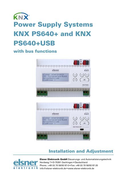
<strong>Power</strong> <strong>Supply</strong> <strong>Systems</strong><br />
<strong>KNX</strong> <strong>PS640+</strong> <strong>and</strong> <strong>KNX</strong><br />
<strong>PS640+</strong>USB<br />
with bus functions<br />
Installation <strong>and</strong> Adjustment<br />
Elsner Elektronik GmbH Steuerungs- und Automatisierungstechnik<br />
Herdweg 7 • D-75391 Gechingen Deutschl<strong>and</strong><br />
Phone.: +49 (0) 70 56/93 97-0 Fax: +49 (0) 70 56/93 97-20<br />
info@elsner-elektronik.de www.elsner-elektronik.de
Contents<br />
Product description ....................................................................................................... 3<br />
Technical data ...................................................................................................................................... 3<br />
Installation <strong>and</strong> Commissioning .................................................................................... 4<br />
Installation ............................................................................................................................................ 5<br />
Settings of the device ................................................................................................... 6<br />
Starting position .................................................................................................................................. 6<br />
Line reset .............................................................................................................................................. 7<br />
Data memory ....................................................................................................................................... 7<br />
Operating data ..................................................................................................................................... 8<br />
Language .............................................................................................................................................. 9<br />
Transmission protocol ................................................................................................... 9<br />
Abbreviations ....................................................................................................................................... 9<br />
Listing of all communication objects ............................................................................................... 10<br />
Setting of parameters (Software ETS) ......................................................................... 11<br />
General settings ................................................................................................................................. 11<br />
Messages ............................................................................................................................................ 12<br />
Current threshold value .................................................................................................................... 14<br />
<strong>KNX</strong> <strong>PS640+</strong> und <strong>KNX</strong> <strong>PS640+</strong>USB from software version 1.01, ETS programme version 1.1<br />
Version: 31/05/2012. Errors excepted. Subject to technical changes.<br />
2
Product description<br />
The <strong>Power</strong> <strong>Supply</strong> <strong>Systems</strong> <strong>KNX</strong> <strong>PS640+</strong> <strong>and</strong> <strong>KNX</strong> <strong>PS640+</strong>USB deliver a 29 V bus<br />
voltage for the <strong>KNX</strong> system <strong>and</strong> 24 V DC supply voltage for 24 V devices. Special<br />
operating conditions such as short circuit, electrical surge, overcharge or excess<br />
temperature are recorded <strong>and</strong> may be read off on the display. The present power<br />
discharge is displayed as well. It is possible to reset the connected bus devices directly<br />
by means of the key pad.<br />
In addition all functions can be realised via the bus, too, e. g. the transfer of malfunction<br />
messages <strong>and</strong> operating data <strong>and</strong> a time/period reset. Malfunction messages are stored<br />
by the <strong>KNX</strong> <strong>PS640+</strong>(USB).<br />
Functions:<br />
Delivers a 29 V <strong>KNX</strong> bus voltage (reduced), output current max. 640 mA, shortcircuit<br />
proof<br />
Delivers 24 V DC (not reduced), output current max. 150 mA<br />
Reset of a line directly on the device<br />
Record of operating hours, overload, external overvoltage, internal overvoltage,<br />
short circuit <strong>and</strong> excess temperature<br />
Display of operating data bus voltage, bus current <strong>and</strong> temperature of the device<br />
The display may be shown in German, English, Spanish or Dutch<br />
Bus connection for data transfer (e. g. malfunction messages, operating data)<br />
Possibility for reset <strong>and</strong> diagnostics via the bus<br />
Only <strong>KNX</strong> <strong>PS640+</strong>USB: USB interface for bus access via PC<br />
The programme file for <strong>KNX</strong> software ETS (format VD2) is ready for download on the<br />
Elsner Elektronik website at www.elsner-elektronik.de in the “Service” menu.<br />
Technical data<br />
Housing: Plastic material<br />
Colour: White<br />
Mounting: Snap-on fitting on mounting rails<br />
Protection category: IP 20<br />
Dimensions: approx. 123 x 89 x 61 (W x H x D, mm), 7 width units<br />
Weight: approx. 370 g<br />
Ambient temperature: Operation -5…+45 °C, storage -25…+70°C<br />
Ambient air humidity: max. 95% RH, avoid bedewing<br />
Operating voltage: 230 V AC , 50 Hz<br />
Outputs: • <strong>KNX</strong> bus voltage 29 V (reduced),<br />
Output current max. 640 mA, short-circuit proof<br />
• 24 V DC (not reduced), Output current max. 150 mA<br />
• <strong>KNX</strong> data<br />
Data output: <strong>KNX</strong> +/- bus terminal plug<br />
3
BCU type: Own micro controller<br />
PEI type: 0<br />
Group addresses: max. 200<br />
Allocations: max. 200<br />
Communication objects: 27<br />
The following st<strong>and</strong>ards have been considered for the evaluation of the product in<br />
terms of electro magnetic compatibility:<br />
Transient emissions:<br />
EN 60730-1:2000 Section EMV (23, 26, H23, H26) (threshold category: B)<br />
EN 50090-2-2:1996-11 + A1:2002-01 (threshold category: B)<br />
EN 61000-6-3:2001 (threshold category: B)<br />
Interference resistance:<br />
EN 60730-1:2000 Section EMV (23, 26, H23, H26)<br />
EN 50090-2-2:1996-11 + A1:2002-01<br />
EN 61000-6-1:2004<br />
The product has been tested for the above mentioned st<strong>and</strong>ards by an accredited EMV<br />
laboratory.<br />
Installation <strong>and</strong> Commissioning<br />
Attention! Mains voltage! The legal national regulations<br />
must be complied with.<br />
Installation, inspection, commissioning <strong>and</strong> troubleshooting of the power supply<br />
system must only be carried out by a competent electrician. Disconnect all lines to be<br />
assembled, <strong>and</strong> take safety precautions against accidental switch-on.<br />
The power supply is exclusively intended for appropriate use. With each inappropriate<br />
change or non-observance of the instructions for use, any warranty or guarantee claim<br />
will be void.<br />
After unpacking the device, check immediately for any mechanical damages. In case of<br />
transport damage, this must immediately notified to the supplier.<br />
If damaged, the power supply system must not be put<br />
into operation.<br />
If an operation without risk may supposedly not be guaranteed, the plant must be put<br />
out of operation <strong>and</strong> be secured against accidental operation.<br />
The power supply system must only be operated as stationary system, i.e. only in a<br />
fitted state <strong>and</strong> after completion of all installation <strong>and</strong> start-up works, <strong>and</strong> only in the<br />
environment intended for this purpose.<br />
Elsner Elektronik does not assume any liability for changes in st<strong>and</strong>ards after<br />
publication of this instruction manual.<br />
4
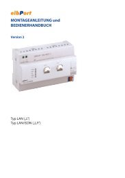
Installation<br />
Observe the correct installation. Incorrect installation may destroy the power supply<br />
system or connected electronic devices.<br />
After the auxiliary voltage is applied the device will enter an initialisation phase lasting 5<br />
seconds. During this phase no information can be received via the bus.<br />
Housing<br />
Scheme<br />
Auxiliary supply 24 V DC<br />
(max. 150 mA)<br />
1 Bus voltage power<br />
OUT (<strong>KNX</strong> terminal + / -)<br />
2 Programming LED <strong>and</strong><br />
programming bushbutton<br />
3 Bus data (<strong>KNX</strong> terminal<br />
+ / -), connection for line<br />
or main line or sector<br />
4 Input operating voltage<br />
230 V AC, L / N / PE<br />
5 USB interface<br />
(only <strong>KNX</strong> <strong>PS640+</strong>USB)<br />
6 Output direct current<br />
voltage 24 V DC, + / -<br />
Connections 4 <strong>and</strong> 6 are<br />
suitable for solid conductors<br />
up to 1.5 mm² or conductors<br />
with fine wires.<br />
5
Connection example for a <strong>KNX</strong> system without line coupler<br />
Connection example for a <strong>KNX</strong> system with line coupler<br />
Settings of the device<br />
Starting position<br />
The following may be read off <strong>and</strong> set on the display of the <strong>Power</strong> <strong>Supply</strong> System <strong>KNX</strong><br />
<strong>PS640+</strong>:<br />
Reset of a line<br />
Recall of the data memory with operating hours, overcharge, external electrical<br />
surge, internal electrical surge, short circuit <strong>and</strong> excess temperature<br />
Recall of the operating data bus voltage, bus current <strong>and</strong> temperature<br />
Language of display<br />
6<br />
elsner elektronik<br />
<strong>KNX</strong> <strong>Power</strong> <strong>Supply</strong><br />
Normal Operation<br />
Diagnostics >
The display is dimmed after 60 seconds if during this period no key is pressed.<br />
Line reset<br />
elsner elektronik<br />
<strong>KNX</strong> <strong>Power</strong> <strong>Supply</strong><br />
Normal Operation<br />
Diagnostics ><br />
Line Reset > <br />
Data Memory ><br />
Operating Data ><br />
Language<br />
Reset: Yes <br />
No<br />
30 seconds<br />
Reset not active!<br />
In starting position, press key once.<br />
Press key once more in order to get into the sector<br />
“Line reset”.<br />
Move the cursor (flashing rectangle at right edge) to<br />
the desired setting with the keys or <strong>and</strong> confirm<br />
with key .<br />
Yes: Reset is activated. The line is switched to neutral <strong>and</strong> shorted. The<br />
basic setting displays: “Reset is active!”<br />
No: Reset not activated. The power supply system works in normal<br />
operation.<br />
30 seconds: A reset of 30 seconds is started. Afterwards, the line is supplied<br />
with voltage as usual. During the reset state, which lasts 30<br />
seconds, the basic setting displays: “Reset active: XX sec”<br />
(countdown).<br />
With key , you return to the previous menu level.<br />
Data memory<br />
elsner elektronik<br />
<strong>KNX</strong> <strong>Power</strong> <strong>Supply</strong><br />
Normal Operation<br />
Diagnostics ><br />
Line Reset ><br />
Data Memory > <br />
Operating Data ><br />
Language ><br />
Hours ofOperation> <br />
Overload ><br />
Ext. Overvoltage ><br />
Int. Overvoltage ><br />
In starting position, press key once.<br />
Move the cursor (flashing rectangle at right edge) to<br />
the “Data memory” menu with the keys <strong>and</strong> <strong>and</strong><br />
confirm with key .<br />
Short circuit ><br />
Excess Temperat. ><br />
Move the cursor to the desired menu with the up <strong>and</strong> down keys <strong>and</strong> press key .<br />
7
Operating Hours<br />
8<br />
Run time: 0 years<br />
0 day 0 hrs.<br />
< = Back<br />
Overload<br />
Overload detected<br />
0 times. Duration:<br />
0 day. 0 hrs. 0 min<br />
< = Back<br />
External Overvoltage<br />
External Overvoltage<br />
was detected<br />
0 times.<br />
< = Back<br />
Internal Overvoltage<br />
Internal Overvoltage<br />
was detected<br />
0 times.<br />
< = Back<br />
Short Circuit<br />
A short at the bus<br />
was detected<br />
0 times.<br />
< = Back<br />
Excess Temperature<br />
Excess Temperature<br />
on the board<br />
was detected<br />
0 times!<br />
Operating data<br />
elsner elektronik<br />
<strong>KNX</strong> <strong>Power</strong> <strong>Supply</strong><br />
Normal Operation<br />
Diagnostics ><br />
he operating hours of the power supply system are<br />
displayed in years, days <strong>and</strong> hours.<br />
With key you return to the previous menu level.<br />
The number of overload incidents <strong>and</strong> the total time in<br />
days, hours <strong>and</strong> minutes are displayed.<br />
With key you return to the previous menu level.<br />
The number of external overvoltage incidents is<br />
displayed.<br />
With key you return to the previous menu level.<br />
The number of internal overvoltage incidents is<br />
displayed.<br />
With key you return to the previous menu level.<br />
The number of short circuit incidents at the bus is<br />
displayed.<br />
With key you return to the previous menu level.<br />
The number of excess temperature incidents on the<br />
circuit board of the device is displayed.<br />
With key you return to the previous menu level.<br />
In starting position, press key once.
Line Reset ><br />
Data Memory ><br />
Operating Data > <br />
Language ><br />
Bus Voltage 29.4 V<br />
Bus Current 320 mA<br />
Temperature 42.1°C<br />
The current values of<br />
Bus voltage<br />
Bus current<br />
Temperature on the circuit board of the device<br />
are displayed.<br />
With key you return to the previous menu level.<br />
Language<br />
elsner elektronik<br />
<strong>KNX</strong> <strong>Power</strong> <strong>Supply</strong><br />
Normal Operation<br />
Diagnostics ><br />
Line Reset ><br />
Data Memory ><br />
Operating Data ><br />
Language > <br />
Sprache :Deutsch <br />
Language :English<br />
Idioma :Espanol<br />
Taal :Holl<strong>and</strong>s<br />
Move the cursor (flashing rectangle at right edge) to<br />
the “Operating Data” menu with the keys <strong>and</strong> <strong>and</strong><br />
confirm with key .<br />
In starting position, press key once.<br />
Move the cursor (flashing rectangle at right edge) to<br />
the “Language” menu with the keys <strong>and</strong> <strong>and</strong><br />
confirm with the key .<br />
Move the cursor to the desired language with the up<br />
<strong>and</strong> down keys <strong>and</strong> press the key . The display<br />
automatically jumps to the previous menu in the<br />
desired language.<br />
With key you get back by one menu level to the basic setting.<br />
Transmission protocol<br />
Abbreviations<br />
Flags:<br />
C Communication<br />
R Read<br />
W Write<br />
T Transmit<br />
U Update<br />
9
Listing of all communication objects<br />
No. Name Function EIS type Flags<br />
0 Bus voltage [V] Output 14.030 C R T<br />
1 Bus current [mA] Output 9.021 C R T<br />
2 Permanent reset (1 = active | 0 = inactive) Input 1.003 C R W<br />
3 Time reset<br />
(1 = 30 seconds active | 0 = inactive)<br />
4 Reset status of the line<br />
(1 = active | 0 = inactive)<br />
10<br />
Input 1.003 C R W<br />
Output 1.002 C R T<br />
5 Overload (0 = normal | 1 = overload) Output 1.002 C R T<br />
6 external overvoltage<br />
(0 = normal | 1 = overvoltage)<br />
7 internal overvoltage<br />
(0 = normal | 1 = overvoltage)<br />
8 Short circuit<br />
(0 = normal | 1 = short circuit)<br />
9 Overtemperature<br />
(0 = normal | 1 = overtemperature)<br />
10 System defect<br />
(0 = normal | 1 = defect)<br />
11 1 bit malfunction collection<br />
(operation = 0 | fault = 1)<br />
Output 1.002 C R T<br />
Output 1.002 C R T<br />
Output 1.002 C R T<br />
Output 1.002 C R T<br />
Output 1.002 C R T<br />
Output 1.002 C R T<br />
12 8 bit status collection Output 5.010 C R T<br />
13 Date Input 11.001 C R W<br />
14 Time Input 10.001 C R W<br />
15 Recall error information<br />
(1 = No.+1 | 0 = No.-1)<br />
Input 1.008 C R W<br />
16 Message part 1 Output 16.000 C R T<br />
17 Message part 2 Output 16.000 C R T<br />
18 Message part 3 Output 16.000 C R T<br />
19 Message part 4 Output 16.000 C R T<br />
20 Threshold value: 16 bit value [mA] Input / Output 9.021 C R W T U<br />
21 Threshold value:<br />
1 = Increment | 0 = Decrement<br />
Input 1.008 C R W<br />
22 Threshold value: Increment Input 1.017 C R W<br />
23 Threshold value: Decrement Input 1.017 C R W<br />
24 Threshold value: Switching output Output 1.002 C R T<br />
25 Threshold value: Switching output block Input 1.003 C R W<br />
26 Software version readable 217.001 C R
Setting of parameters (Software ETS)<br />
General settings<br />
Measured values:<br />
……………………………<br />
Transmission behaviour object “bus voltage” do not send<br />
send cyclically<br />
send in case of change<br />
send in case of change <strong>and</strong> cyclically<br />
Sending cycle<br />
(only if sending “cyclically”)<br />
Change in %<br />
(only if sending “in case of change”)<br />
5 sec 10 sec 30 sec 1 min … 2 h<br />
1 … 50<br />
Transmission behaviour object “bus current” do not send<br />
send cyclically<br />
send in case of change<br />
send in case of change <strong>and</strong> cyclically<br />
Sending cycle<br />
(only if sending “cyclically”)<br />
Change in %<br />
(only if sending “in case of change”)<br />
5 sec 10 sec 30 sec 1 min … 2 h<br />
1 … 100<br />
11
Reset of the linie:<br />
……………………………<br />
What shall be used for the reset?<br />
display <strong>and</strong> keyboard Yes<br />
object “permanent reset”<br />
1 = reset | 0 = no reset<br />
object “time reset”<br />
1 = 30 seconds reset | 0 = no reset<br />
12<br />
No Yes<br />
No Yes<br />
Use object “reset status of the line” No Yes<br />
Other:<br />
……………………………<br />
Maximum telegram quota 1 2 3 5 10 20 Telegrams per second<br />
General sending delay after<br />
power up <strong>and</strong> programming<br />
Messages<br />
5 sec 10 sec 30 sec 1 min … 2 h<br />
1 bit malfunction objects:<br />
……………………………<br />
Object “overload” do not send<br />
send in case of change<br />
send in case of change to 1<br />
send in case of change to 0<br />
send in case of change <strong>and</strong> cyclically<br />
send in case of change to 1 <strong>and</strong> cyclically<br />
send in case of change to 0 <strong>and</strong> cyclically
Sending cycle<br />
(only if sending “cyclically”)<br />
5 sec 10 sec 30 sec 1 min … 2 h<br />
Object “external overvoltage” [The setting options are similar to object<br />
“overload”]<br />
Object “internal overvoltage” [The setting options are similar to object<br />
“overload”]<br />
Object “short circuit” [The setting options are similar to object<br />
“overload”]<br />
Object “overtemperature” [The setting options are similar to object<br />
“overload”]<br />
Object “system defect” [The setting options are similar to object<br />
“overload”]<br />
1 bit malfunction collection:<br />
……………………………<br />
Object “1 bit malfunction collection”<br />
This object results in a<br />
disjunction of the 1 bit malfunction objects<br />
Sending cycle<br />
(only if sending “cyclically”)<br />
do not send<br />
send in case of change<br />
send in case of change to 1<br />
send in case of change to 0<br />
send in case of change <strong>and</strong> cyclically<br />
send in case of change to 1 <strong>and</strong> cyclically<br />
send in case of change to 0 <strong>and</strong> cyclically<br />
5 sec 10 sec 30 sec 1 min … 2 h<br />
8 bit status collection:<br />
……………………………<br />
Object “8 bit status collection” do not send<br />
send in case of change<br />
send in case of change <strong>and</strong> cyclically<br />
Sending cycle<br />
(only if sending “cyclically”)<br />
Bit 0 = reset status of the linie<br />
Bit 1 = overload<br />
Bit 2 = external overvoltage<br />
Bit 3 = internal overvoltage<br />
Bit 4 = short circuit<br />
Bit 5 = overtemperature<br />
Bit 6 = current threshold value exceeded<br />
Bit 7 = system defect<br />
5 sec 10 sec 30 sec 1 min … 2 h<br />
= value 1<br />
= value 2<br />
= value 4<br />
= value 8<br />
= value 16<br />
= value 32<br />
= value 64<br />
= value 128<br />
A combination of error messages is possible. If e.g. value 34 is transferred, then Bit 1 =<br />
Overload <strong>and</strong> Bit 5 = Overtemperature are set.<br />
The value set in the menu “current threshold value” (see next chapter) is used as<br />
current threshold value. The additional settings for hysteresis etc. are not taken into<br />
account for the status collection. Bit 6 “current threshold status exceeded” is set, if the<br />
13
threshold value has been exceeded for 1 minute. The bit is immediately deleted again, if<br />
the threshold value is underrun.<br />
Error log:<br />
……………………………<br />
Use error log No Yes<br />
If the error log is used:<br />
Object “message part 1” sends signal:<br />
Error no. (1 = latest error)<br />
Object “message part 2” sends signal:<br />
Error type<br />
Object “message part 3” sends signal:<br />
Date of error start<br />
Object “message part 4” sends signal:<br />
Time of error start<br />
Current threshold value<br />
Use threshold value No Yes<br />
If the threshold value is used:<br />
Threshold value:<br />
……………………………<br />
If the threshold value is set by parameter:<br />
Threshold value is set by Parameter<br />
14
Threshold value in mA 0 … 640<br />
Hysteresis of the threshold value in % 0 … 50<br />
If the threshold value is set by communication object:<br />
Threshold value is set by Communication object<br />
The value communicated last shall be<br />
maintained<br />
Start threshold value in mA<br />
valid until 1. communication<br />
(only if the value communicated last is “not”<br />
maintained or “after restoration of voltage”)<br />
not<br />
after restoration of voltage<br />
after restoration of voltage <strong>and</strong><br />
programming (Do not use for first<br />
commissioning)<br />
0 … 640<br />
Type of threshold change Absolute value with a 16 bit com.object<br />
Increment/decrement with one comm. object<br />
Increment/decrement with two comm.<br />
objects<br />
Step size in mA<br />
(only with “increment/decrement”)<br />
Hysteresis of the threshold value in % 0 … 50<br />
Switching output:<br />
……………………………<br />
Output is at<br />
(TV = Threshold value)<br />
1 2 5 10 20 50 100<br />
TV above = 1 | TV – hyst. below = 0<br />
TV above = 0 | TV – hyst. below = 1<br />
TV below = 1 | TV + hyst. above = 0<br />
TV below = 0 | TV + hyst. above = 1<br />
Switching delay from 0 to 1 none 1 s 2 s 5 s 10 s … 2 h<br />
Switching delay from 1 to 0 none 1 s 2 s 5 s 10 s … 2 h<br />
Switching output sends send in case of change<br />
send in case of change to 1<br />
send in case of change to 0<br />
send in case of change <strong>and</strong> cyclically<br />
send in case of change to 1 <strong>and</strong> cyclically<br />
send in case of change to 0 <strong>and</strong> cyclically<br />
Send switching output in a cycle of<br />
(only if sending “cyclically”)<br />
Blocking:<br />
……………………………<br />
Use block of the switching output No Yes<br />
If the block of the switching output is used:<br />
Use block of the switching output Yes<br />
5 sec 10 sec 30 sec 1 min … 2 h<br />
15
Evaluation of the blocking object if value 1: block | if value 0: release<br />
if value 0: block | if value 1: release<br />
Value of the blocking object<br />
before 1. communication<br />
Bahaviour of switching output<br />
16<br />
0 1<br />
with blocking do not send telegram<br />
send 0<br />
send 1<br />
The behaviour with release of the switching output depends on the value of the<br />
parameter “Switching output sends …” (see ”Switching output”)<br />
Value of parameter<br />
“Switching output sends”:<br />
Setting options “Behaviour of the switching<br />
output with release”:<br />
in case of change do not send telegram<br />
send status of the switching output<br />
in case of change to 1 do not send telegram<br />
if switching output = 1 send 1<br />
in case of change to 0 do not send telegram<br />
if switching output = 0 send 0<br />
in case of change <strong>and</strong> cyclically send status of the switching output<br />
(no selection)<br />
in case of change to 1 <strong>and</strong> cyclically if switching output = 1 send 1<br />
(no selection)<br />
in case of change to 0 <strong>and</strong> cyclically if switching output = 0 send 0<br />
(no selection)