theben
theben
theben

Create successful ePaper yourself
Turn your PDF publications into a flip-book with our unique Google optimized e-Paper software.
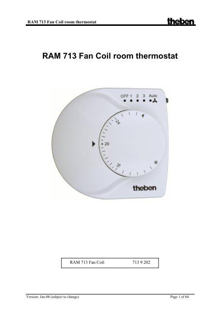
RAM 713 Fan Coil room thermostat <strong>theben</strong><br />
RAM 713 Fan Coil room thermostat<br />
RAM 713 Fan Coil 713 9 202<br />
Version: Jan-08 (subject to change) Page 1 of 64
RAM 713 Fan Coil room thermostat <strong>theben</strong><br />
Contents<br />
1 Functional characteristics................................................................................................... 4<br />
1.1 Operation.................................................................................................................... 5<br />
1.2 The device LEDs........................................................................................................ 5<br />
1.3 Benefits of RAM 713 FAN COIL.............................................................................. 6<br />
1.3.1 Special features .................................................................................................. 6<br />
2 Technical data .................................................................................................................... 7<br />
3 The "RAM 713 FAN COIL V1.0"application program...................................................... 8<br />
3.1 Selection in the product database............................................................................... 8<br />
3.2 Parameter pages.......................................................................................................... 8<br />
3.3 Communication objects.............................................................................................. 9<br />
3.3.1 Object characteristics ......................................................................................... 9<br />
3.3.2 Description of objects....................................................................................... 11<br />
3.4 Parameters ................................................................................................................ 15<br />
3.4.1 Settings ............................................................................................................. 15<br />
3.4.2 Setpoint values.................................................................................................. 16<br />
3.4.3 Cooling setpoint values .................................................................................... 18<br />
3.4.4 Operation ......................................................................................................... 19<br />
3.4.5 Actual value...................................................................................................... 22<br />
3.4.6 Control ............................................................................................................. 24<br />
3.4.7 Operating mode................................................................................................ 27<br />
3.4.8 Inputs E1, E2, E3.............................................................................................. 29<br />
4 Start-up............................................................................................................................. 31<br />
4.1 Actuators to control heating and cooling ................................................................. 31<br />
4.2 Control variable display ........................................................................................... 31<br />
5 Typical applications: ........................................................................................................ 32<br />
5.1 Base configuration (4-pipe system): Heating and cooling with RAM 713 FC as<br />
external control for FCA 1 ................................................................................................... 32<br />
5.1.1 Devices:............................................................................................................ 32<br />
5.1.2 Overview .......................................................................................................... 32<br />
5.1.3 Objects and links .............................................................................................. 32<br />
5.1.4 Important parameter settings............................................................................ 33<br />
5.2 Base configuration (2-pipe system): Heating and cooling with RAM 713 FC as<br />
external control for FCA 1 ................................................................................................... 34<br />
5.2.1 Special features ................................................................................................ 34<br />
5.2.2 Devices:............................................................................................................ 34<br />
5.2.3 Overview .......................................................................................................... 34<br />
5.2.4 Objects and links .............................................................................................. 35<br />
5.2.5 Important parameter settings............................................................................ 35<br />
5.3 Typical application (4-pipe system):........................................................................ 36<br />
5.3.1 Function:........................................................................................................... 36<br />
5.3.2 Devices:............................................................................................................ 36<br />
5.3.3 Overview .......................................................................................................... 36<br />
5.3.4 Implementation: ............................................................................................... 37<br />
Objects and links .............................................................................................................. 38<br />
5.3.5 Important parameter settings............................................................................ 39<br />
Version: Jan-08 (subject to change) Page 2 of 64
RAM 713 Fan Coil room thermostat <strong>theben</strong><br />
5.4 Switching, blinds control a dimming with devices in the MiX range, in addition to<br />
control operating mode......................................................................................................... 40<br />
5.4.1 Devices:............................................................................................................ 40<br />
5.4.2 Overview .......................................................................................................... 40<br />
5.4.3 Objects and links .............................................................................................. 41<br />
5.4.4 Important parameter settings............................................................................ 42<br />
5.4.5 Frost protection via window contact ................................................................ 43<br />
6 Appendix.......................................................................................................................... 44<br />
6.1 Fan forced mode....................................................................................................... 44<br />
6.1.1 Forced mode via bus telegrams........................................................................ 45<br />
6.2 Determining the current operating mode ................................................................. 46<br />
6.2.1 New operating modes....................................................................................... 46<br />
6.2.2 Old operating modes ........................................................................................ 47<br />
6.2.3 Determining the setpoint value ........................................................................ 48<br />
6.3 Setpoint offset .......................................................................................................... 50<br />
6.3.1 Setpoint temperature offset using the rotary control........................................ 50<br />
6.3.2 Setpoint temperature offset via Object 0.......................................................... 51<br />
6.3.3 Setting the presence object with setpoint value offset ..................................... 51<br />
6.4 External interface ..................................................................................................... 52<br />
6.4.1 Overview: Function of Objects 9 .. 14. ............................................................ 53<br />
6.4.2 E1...E3 as switching inputs .............................................................................. 54<br />
6.4.3 E1…E2 Blinds Up / Down............................................................................... 55<br />
6.4.4 Blinds single-surface operation........................................................................ 55<br />
6.4.5 E1 E2 Dim brighter / darker........................................................................... 56<br />
6.4.6 Dimming single-surface operation................................................................... 56<br />
6.4.7 E3 as an analogue input for an external sensor ................................................ 57<br />
6.4.8 Suitable actuators ............................................................................................. 57<br />
6.5 Temperature control ................................................................................................. 58<br />
6.5.1 Introduction ...................................................................................................... 58<br />
6.5.2 Response of the P-control ................................................................................ 59<br />
6.5.3 Response of the PI control ............................................................................... 60<br />
7 Glossary............................................................................................................................ 61<br />
7.1 Continuous and switching control............................................................................ 61<br />
7.2 Hysteresis ................................................................................................................. 61<br />
7.2.1 Negative hysteresis:.......................................................................................... 61<br />
7.2.2 Positive hysteresis ............................................................................................ 62<br />
7.3 Dead zone................................................................................................................. 62<br />
7.3.1 Heating and cooling with continuous control .................................................. 62<br />
7.4 Base setpoint value and current setpoint value ........................................................ 63<br />
7.4.1 Setpoint value calculation ................................................................................ 64<br />
Version: Jan-08 (subject to change) Page 3 of 64
RAM 713 Fan Coil room thermostat <strong>theben</strong><br />
1 Functional characteristics<br />
The RAM 713 FAN COIL room thermostat is a continuous EIB room thermostat for<br />
ventilator convectors (fan coil) in 2 and 4 pipe systems.<br />
It measures the current room temperature (actual value) and sends a continuous control<br />
variable (0...100%) to a fan coil actuator (FCA 1 order no. 492 0 200) to achieve the desired<br />
room temperature (setpoint value).<br />
The RAM 713 fan coil works in both heating and cooling modes.<br />
A fan step can also be selected manually via a button.<br />
3 binary inputs (see external interface) are available for connecting switches or buttons<br />
(floating) for switching, dimming or controlling blinds.<br />
The blinds and dimmer channels can also be controlled with a single button (single-surface<br />
operation)<br />
An external temperature sensor can alternatively be connected to input 3 (analogue).<br />
In order to easily adapt to the setpoint values in respect of living comfort and energy saving,<br />
RAM 713 FAN COIL has four operating modes:<br />
• Comfort<br />
• Standby<br />
• Night mode<br />
• Frost protection mode<br />
A setpoint value is assigned to each operating mode.<br />
comfort mode is used when the room is occupied<br />
The setpoint value is reduced slightly in standby mode. This operating mode is used when<br />
the room is not occupied but is expected to be shortly.<br />
The setpoint value is drastically reduced in night mode as the room is not expected to be<br />
occupied for several hours.<br />
In frost protection mode , the room is controlled to a temperature that eliminates the risk of<br />
damage to the radiators through freezing at low outdoor temperatures.<br />
This can be desirable for 2 reasons:<br />
- The room is not occupied for several days.<br />
- A window has been opened and no further heating is required for the time being.<br />
The operating modes are usually controlled by a time switch.<br />
However, a presence detector and/or presence keys and window contacts are recommended<br />
for optimum control.<br />
See determining the setpoint value chapter.<br />
Version: Jan-08 (subject to change) Page 4 of 64
RAM 713 Fan Coil room thermostat <strong>theben</strong><br />
1.1 Operation<br />
The RAM 713 FAN COIL is fitted with a rotary control and 5 LEDs to display the current fan<br />
step.<br />
The fan step can also be set manually using the button to the right of the LEDs (forced mode).<br />
1.2 The device LEDs<br />
Table 1<br />
LED Display Description<br />
Auto Fan is in automatic mode Fan step is controlled, as configured, depending on the<br />
control variable.<br />
0 Fan step 0 = fan is off.<br />
1 Fan step 1<br />
2 Fan step 2<br />
3 Fan step 3<br />
See operation parameter page .<br />
Forced mode:<br />
Fan step is selected manually by pressing the button.<br />
Depending on the configuration, the rotary control can be used for either setpoint adjustment<br />
or for setpoint offset.<br />
Version: Jan-08 (subject to change) Page 5 of 64
RAM 713 Fan Coil room thermostat <strong>theben</strong><br />
1.3 Benefits of RAM 713 FAN COIL<br />
• Continuous PI room thermostat<br />
• Fan step can be preselected manually<br />
• Operating mode change via presence and window objects<br />
• Heating and cooling operation<br />
• Rotary control for setting or offsetting setpoint value<br />
• Infinite regulation through continuous control variable<br />
• 3 Binary inputs for conventional control of switch, dimmer<br />
and blinds actuators<br />
• Third input also for external temperature sensor for determining room temperature<br />
• Adjustable effect with binary inputs<br />
• Blinds and dimmers can also be controlled using single-surface operation<br />
1.3.1 Special features<br />
RAM 713 FAN COIL has 3 external inputs for buttons, switches or an external sensor. These<br />
can be used to control switch, dimmer or blinds actuators.<br />
Version: Jan-08 (subject to change) Page 6 of 64
RAM 713 Fan Coil room thermostat <strong>theben</strong><br />
2 Technical data<br />
Power supply: Bus voltage<br />
Permitted operating temperature: 0°C ...+ 50°C<br />
Protection class: III<br />
Protection rating: EN 60529: IP 21<br />
Dimensions: HxWxD 80x84x28 (mm)<br />
Inputs:<br />
Quantity: 3<br />
Contact voltage: 3.3 V internal provided<br />
Contact current: 1 mA<br />
Maximum line length: 5 m<br />
Version: Jan-08 (subject to change) Page 7 of 64
RAM 713 Fan Coil room thermostat <strong>theben</strong><br />
3 The "RAM 713 FAN COIL V1.0" application<br />
program<br />
3.1 Selection in the product database<br />
Manufacturer Theben AG<br />
Product family Heating, ventilation, air conditioning<br />
Product type Fan coil controller<br />
Program name RAM 713 Fan Coil with switching, dimming, blinds V1.0<br />
The ETS database can be found on our website: http://www.<strong>theben</strong>.de<br />
3.2 Parameter pages<br />
Table 2<br />
Function Description<br />
Settings Device type and activation of external interface.<br />
Setpoint values Setpoint value after download, values for night, frost mode etc.<br />
Setpoint values for Dead zone and temperature increases conditional on the operating<br />
cooling<br />
mode<br />
Operation Rotary control and button functions.<br />
Actual value Sensor type/function, calibration<br />
Control System type, heating/ cooling parameters etc.<br />
Operating mode Operating mode after reset, presence sensor<br />
Input E1...E3 Function of connected contact, switches, dimmers, blinds.<br />
Version: Jan-08 (subject to change) Page 8 of 64
RAM 713 Fan Coil room thermostat <strong>theben</strong><br />
3.3 Communication objects<br />
3.3.1 Object characteristics<br />
RAM 713 FAN COIL features 12 communication objects.<br />
Some objects can assume various functions depending on their configuration.<br />
Table 3<br />
No<br />
.<br />
Flags<br />
Function Object name Type C R W T<br />
0<br />
Defining the setpoint<br />
temperature<br />
offset<br />
Basesetpointvalue<br />
Manual setpoint offset<br />
2 bytes<br />
<br />
EIS5<br />
2 bytes<br />
<br />
EIS5<br />
1 report current setpoint value currents etpointvalue<br />
2 bytes<br />
<br />
EIS5<br />
<br />
2 Send actual value Actual value<br />
2 bytes<br />
<br />
EIS5<br />
<br />
3<br />
Operating mode preset<br />
1 = night, 0 = standby<br />
Operating mode preset<br />
Night < - > Standby<br />
1 byte<br />
KNX<br />
1-bit<br />
EIS1<br />
<br />
<br />
4<br />
Input for presence signal<br />
1 = Comfort<br />
Presence<br />
Comfort<br />
1-bit<br />
EIS1<br />
1-bit<br />
EIS1<br />
<br />
<br />
5<br />
Input for windowstatus<br />
1 = Frost protection<br />
Window position<br />
Frost / heat protection<br />
1-bit<br />
EIS1<br />
1-bit<br />
EIS1<br />
1 byte<br />
<br />
<br />
6 report current operating mode current operating mode KNX<br />
DTP<br />
<br />
7<br />
Send current control variable<br />
Send current control variable<br />
Heating control variable<br />
Heating and cooling control<br />
variable<br />
1-byte<br />
EIS6<br />
1-byte<br />
EIS6<br />
<br />
<br />
<br />
<br />
8 Send control variable Cooling control variable<br />
1-byte<br />
EIS6<br />
<br />
C R W T<br />
Version: Jan-08 (subject to change) Page 9 of 64
RAM 713 Fan Coil room thermostat <strong>theben</strong><br />
Continuation:<br />
No<br />
.<br />
Flags<br />
Function Object name Type C R W T<br />
Send switch telegram Switching input 1 <br />
9<br />
Send ON/OFF telegram<br />
Send ON/OFF telegram<br />
Slats<br />
Dimmer E1 On/Off<br />
Dimmer E1/E2 On/Off<br />
Blinds E1 Step/Stop<br />
1-bit<br />
EIS1<br />
<br />
<br />
<br />
<br />
<br />
<br />
Slats Blinds E1/E2 Step/Stop<br />
<br />
Send Up/Down telegram<br />
10<br />
Send dim telegram<br />
Blinds E1 Up/Down<br />
Dimmer E1<br />
1-bit<br />
EIS1<br />
4-bit<br />
EIS2<br />
<br />
<br />
<br />
<br />
Send switch telegram<br />
11 Send ON/OFF telegram<br />
Slats<br />
Switching input 2<br />
Dimmer E2 On/Off<br />
Blinds E2 Step/Stop<br />
1-bit<br />
EIS 1<br />
<br />
<br />
<br />
<br />
<br />
<br />
Blinds E2 Up/Down Send Up/Down telegram 1-bit <br />
Blinds E1/E2 Up/Down<br />
12<br />
Dimmer E2<br />
Send Up/Down telegram<br />
Send dim telegram<br />
EIS 1<br />
4-bit<br />
<br />
<br />
<br />
<br />
Dimmer E1/E2 Send dim telegram<br />
EIS2 <br />
Send switch telegram<br />
13 Send ON/OFF telegram<br />
Slats<br />
Switching input 3<br />
Dimmer E3 On/Off<br />
Blinds E3 Step/Stop<br />
1-bit<br />
EIS1<br />
<br />
<br />
<br />
<br />
<br />
<br />
Blinds E2 Up/Down<br />
14<br />
Dimmer E3<br />
Send Up/Down telegram<br />
Send dim telegram<br />
1-bit<br />
EIS1<br />
4-bit<br />
EIS2<br />
<br />
<br />
<br />
<br />
15 Heating = 0, Cooling = 1<br />
Switchover between heating<br />
and cooling<br />
1-bit<br />
EIS1<br />
<br />
16 send/receive Forced fan step<br />
1-byte<br />
EIS 6<br />
<br />
17 0 = Auto / 1 = Forced Fan forced/auto mode<br />
1-bit<br />
EIS1<br />
<br />
C R W T<br />
Table 4: Communication flags<br />
Flag Name Meaning<br />
C Communication Object can communicate<br />
R Read Object status can be viewed (ETS / display etc.)<br />
W Write Object can receive<br />
T Transmit Object can transmit<br />
Table 5<br />
Number of communication objects 18<br />
Number of group addresses 34<br />
Number of associations 35<br />
Version: Jan-08 (subject to change) Page 10 of 64
RAM 713 Fan Coil room thermostat <strong>theben</strong><br />
3.3.2 Description of objects<br />
• Object 0 “base setpoint value” / “manual setpoint value offset”<br />
This object can assume 2 different functions.<br />
Depending on the configuration of the rotary control, a new setpoint temperature can be set or<br />
the current setpoint temperature offset by a certain value<br />
Table 6.<br />
Parameters: Rotary control function Object function<br />
Manual offset for internal controller Defining the setpoint temperature:<br />
The base setpoint value is first specified at start-up<br />
disabled, but base setpoint value object and stored in the base setpoint value object.<br />
available<br />
It can be reset at any time using object 0 (limited by<br />
minimum or maximum valid setpoint value).<br />
If the bus voltage fails, this object is backed up and<br />
the last value is restored when the bus voltage<br />
returns. The object can be described as required.<br />
Base setpoint value for internal<br />
controller<br />
disabled, but manual offset object<br />
available<br />
Manual offset with report object, e.g.<br />
for FCA 1<br />
• Object 1 "current setpoint value"<br />
Offset setpoint temperature:<br />
The object receives a temperature differential in EIS<br />
5 format. The desired room temperature (current<br />
setpoint value) can be adjusted from the base<br />
setpoint value by this differential.<br />
The following applies in comfort mode (heating):<br />
current setpoint value (object 1) = base setpoint<br />
value (rotary control) + manual setpoint value offset<br />
(object 0)<br />
Values outside the configurable range (see Max.<br />
rotary control setpoint value offset) are limited to<br />
the highest or lowest value.<br />
Note:<br />
The offset always refers to the set base setpoint<br />
value and not to the current setpoint value.<br />
Object 0 sends the rotary control offset to the fan<br />
coil actuator FCA 1.<br />
This object sends the current setpoint temperature as a EIS 5 telegram (2 bytes) to the bus.<br />
The send response can be set on the setpoint values parameter page.<br />
Version: Jan-08 (subject to change) Page 11 of 64
RAM 713 Fan Coil room thermostat <strong>theben</strong><br />
• Object 2 “actual value”<br />
This object sends the temperature currently being measured by the sensor (if sending via<br />
configuration is permitted)<br />
• Object 3 "operating mode preset" / "night standby"<br />
The function of this object depends on the objects for setting operating mode parameter on<br />
the operating mode parameter page.<br />
Table 7<br />
Objects for determining the operating Object function<br />
mode<br />
new: Operating mode, presence, 1-byte object for selection of one of<br />
window status<br />
4 operating modes.<br />
1 = Comfort, 2 = Standby, 3 = Night,<br />
4 = Frost protection (heat protection)<br />
If another value is received (0 or >4) the comfort<br />
operating mode is activated.<br />
The details in brackets refer to cooling mode<br />
old: Comfort, night, frost With this setting, this object is a 1-bit object. Night<br />
or standby operating mode can be activated.<br />
0=Standby 1=Night<br />
• Object 4 "presence" / "comfort"<br />
The function of this object depends on the objects for setting operating mode parameter on<br />
the operating mode parameter page.<br />
Table 8<br />
Objects for determining the operating Object function<br />
mode<br />
new: Operating mode, presence, Presence:<br />
window status<br />
The status of a presence indicator (e.g. sensor,<br />
motion detector) can be received via this object.<br />
1 on this object activates the comfort operating<br />
mode.<br />
old: Comfort, night, frost Comfort:<br />
1 on this object activates the comfort operating<br />
mode.<br />
This operating mode takes priority over night and<br />
standby modes.<br />
Comfort mode is deactivated by sending a 0 to the<br />
object.<br />
Version: Jan-08 (subject to change) Page 12 of 64
RAM 713 Fan Coil room thermostat <strong>theben</strong><br />
• Object 5 “window position” / “frost/heat protection”<br />
The function of this object depends on the objects for setting operating mode parameter on<br />
the operating mode parameter page.<br />
Table 9<br />
Objects for determining the operating Object function<br />
mode<br />
new: Operating mode, presence, Window position:<br />
window status<br />
The status of a window contact can be received via<br />
this object.<br />
1 on this object activates the frost / heat protection<br />
operating mode.<br />
old: Comfort, night, frost Frost/heat protection:<br />
1 on this object activates the frost protection<br />
operating mode.<br />
The heat protection mode is activated during<br />
cooling.<br />
The frost/heat protection operating mode takes top<br />
priority.<br />
The frost/heat protection mode remains until it is<br />
cleared again by entering 0.<br />
• Object 6 "current operating mode"<br />
Transmits the current operating mode as a 1 byte value (see below: Coding of operating<br />
modes).<br />
The send response can be set on the operating mode parameter page.<br />
Table 10: Coding of HVAC operating modes:<br />
Value Operating mode<br />
1 Comfort<br />
2 Standby<br />
3 Night<br />
4 Frost protection/heat<br />
protection<br />
Version: Jan-08 (subject to change) Page 13 of 64
RAM 713 Fan Coil room thermostat <strong>theben</strong><br />
• Object 7 “heating control variable” / “heating and cooling control variable”<br />
Sends the current heating control variable (0...100%) or heating or cooling with 2-pipe<br />
system. See fan coil system used parameter on the controlparameter page.<br />
• Object 8 "cooling control variable"<br />
Sends the cooling control variable in EIS 6 format<br />
• Objects 9, 10, 11, 12, 13, 14 for inputs E1, E2 and E3<br />
These objects are available when the interface on the settings parameter page is activated.<br />
Their function is dependent on the function of E1, function of E2 and function of E3<br />
parameters on the relevant parameter pages (input E1, E2 and E3).<br />
A detailed description can be found in the appendix under the heading: External interface.<br />
• Object 15 "switching between heating and cooling"<br />
This object is used in 2-pipe heating/cooling systems or if automatic switching between<br />
heating and cooling is not required.<br />
The cooling operation is forced via 1 and the heating operation via 0.<br />
• Object 16 "fan step in forced mode"<br />
The fan step can be set manually by pressing the button on the device.<br />
This object then sends a percentage value that corresponds to the configured threshold values.<br />
This function can be blocked or time limited or work permanently via a parameter.<br />
See operation parameter page and Fan forced mode in the appendix.<br />
Version: Jan-08 (subject to change) Page 14 of 64
RAM 713 Fan Coil room thermostat <strong>theben</strong><br />
• Object 17 "fan forced/ auto "<br />
Sends when a forced fan step is selected using the button.<br />
This puts the fan coil actuator (FCA 1) in forced mode.<br />
The forced mode is triggered via 0 or 1 depending on the application.<br />
→ See switch fan between auto and forced parameter on the operating parameter page.<br />
The object status is inverted when automatic mode is restored.<br />
The following settings apply for the fan coil actuator FCA 1: Forced= 1, / Auto = 0<br />
3.4 Parameters<br />
The standard values are in bold.<br />
3.4.1 Settings<br />
Table 11<br />
Designation Values Meaning<br />
Device type RAM 713 Fan Coil Fixed setting<br />
Function of external none<br />
Determines whether external<br />
interface<br />
active<br />
interface is being used.<br />
Version: Jan-08 (subject to change) Page 15 of 64
RAM 713 Fan Coil room thermostat <strong>theben</strong><br />
3.4.2 Setpoint values<br />
Table 12<br />
Designation Values Meaning<br />
Basesetpoint value after<br />
downloading application<br />
Minimum valid base setpoint<br />
value<br />
Maximum valid base setpoint<br />
value<br />
Reduction in standby mode<br />
(during heating)<br />
Reduction in night mode<br />
(during heating)<br />
Setpoint value for frost<br />
protection operation (during<br />
heating)<br />
Setpoint value offset only<br />
applies<br />
18 °C, 19 °C, 20 °C,<br />
21 °C, 22 °C, 23 °C,<br />
24 °C, 25 °C<br />
5°C, 6°C, 7°C, 8°C,<br />
9°C, 10°C, 11°C, 12 °C,<br />
13°C, 14°C, 15°C,16°C<br />
17°C, 18°C, 19 °C, 20 °C<br />
20°C, 21°C, 22°C<br />
23°C, 24 °C, 25°C<br />
27 °C, 30 °C, 32 °C<br />
0.5 K, 1 K, 1.5 K<br />
2 K, 2.5 K, 3 K<br />
3.5 K, 4 K<br />
3 K, 4 K, 5 K<br />
6 K, 7 K, 8 K<br />
3 °C, 4 °C, 5 °C<br />
6°C, 7 °C, 8 °C<br />
9 °C, 10 °C<br />
in comfort mode<br />
with comfort and standby<br />
mode<br />
with comfort, standby and<br />
night mode<br />
Output setpoint value for<br />
temperature control.<br />
If a base setpoint value<br />
received by object 0 is lower<br />
than the set value, it will be<br />
limited to this value.<br />
If a base setpoint value<br />
received by object 0 is higher<br />
than the set value, it will be<br />
limited to this value.<br />
Example: with a base setpoint<br />
value of 21°C in heating<br />
operation and a<br />
2K reduction, RAM 713 FAN<br />
COIL controls at a setpoint<br />
value of 21 – 2 = 19°C<br />
By what value should the<br />
temperature be reduced in<br />
night mode?<br />
Preset temperature for frost<br />
protection operation in<br />
heating mode<br />
(Heat protection operation<br />
applies in cooling mode).<br />
In which operating modes is<br />
setpoint value offset<br />
effective?<br />
This setting covers offsetting<br />
via bus telegram as well as<br />
via the rotary control.<br />
Version: Jan-08 (subject to change) Page 16 of 64
RAM 713 Fan Coil room thermostat <strong>theben</strong><br />
Continuation:<br />
Designation Values Meaning<br />
current setpoint value in<br />
Feedback of current setpoint<br />
comfort mode<br />
value via the bus:<br />
cyclical transmission of<br />
current setpoint value<br />
Sends actual value (heating<br />
< > cooling)<br />
Transmits average value<br />
between heating and cooling<br />
not cyclical, only in the event<br />
of change<br />
every 2 min.<br />
every 3 min.<br />
every 5 min.<br />
every 10 min.<br />
every 15 min.<br />
every 20 min.<br />
every 30 min.<br />
every 45 min.<br />
every 60 min.<br />
The setpoint value actually<br />
being controlled is always<br />
sent<br />
(= currelnt setpointvalue).<br />
Example with<br />
basesetpointvalue 21°C and<br />
dead zone 2K:<br />
During heating and cooling,<br />
21°C and base setpoint value<br />
+ dead zone are sent<br />
respectively (21°C + 2K =<br />
23°C)<br />
Same value in comfort<br />
operation mode during both<br />
heating and cooling operation,<br />
i.e.:<br />
Base setpoint value + half<br />
dead zone<br />
are transmitted to prevent<br />
occupants being<br />
inconvenienced.<br />
Example with base<br />
setpointvalue 21°C and<br />
deadzone 2K:<br />
Mean value= 21°+1K =22°C<br />
Although control takes place<br />
at 21°C<br />
or 23°C<br />
How often should the<br />
currently valid setpoint value<br />
be sent?<br />
only send in the event of a<br />
change.<br />
send cyclically<br />
Version: Jan-08 (subject to change) Page 17 of 64
RAM 713 Fan Coil room thermostat <strong>theben</strong><br />
3.4.3 Cooling setpoint values<br />
This page is only displayed only if the “heating and cooling” control function has been<br />
selected on the settings parameter page (user-definedcontrol).<br />
Table 13<br />
Designation Values Meaning<br />
Dead zone between heating<br />
and cooling<br />
Increase in standby mode<br />
(during cooling)<br />
Increase in night mode<br />
(during cooling)<br />
Setpoint value for heat<br />
protection mode<br />
(during cooling)<br />
1 K<br />
2 K<br />
3 K<br />
4 K<br />
5 K<br />
6 K<br />
0.5 K, 1 K, 1.5 K<br />
2 K, 2.5 K, 3 K<br />
3.5 K, 4 K<br />
3 K, 4 K, 5 K<br />
6 K, 7 K, 8 K<br />
42 °C (does not represent<br />
heat protection)<br />
29 °C, 30 °C, 31 °C<br />
32 °C, 33 °C, 34 °C<br />
35 °C<br />
Specifies the buffer zone<br />
between setpoint values in<br />
heating and cooling modes.<br />
The dead zone is expanded<br />
through hysteresis in<br />
switching (2 point) control.<br />
See glossary: Dead zone<br />
The temperature is increased<br />
in standby mode during<br />
cooling operation<br />
See increase in standby mode<br />
Heat protection represents the<br />
maximum permitted<br />
temperature for the controlled<br />
room. It performs the same<br />
function during cooling as the<br />
frost protection mode during<br />
heating, e.g. saves energy<br />
while prohibiting nonpermitted<br />
temperatures<br />
Version: Jan-08 (subject to change) Page 18 of 64
RAM 713 Fan Coil room thermostat <strong>theben</strong><br />
3.4.4 Operation<br />
Table 14<br />
Designation Values Meaning<br />
Function of the rotary control Base setpoint value for The rotary control is used for<br />
internal controller<br />
setting the base setpoint<br />
(please using the following rotary<br />
control)<br />
value.<br />
Setpoint value offset is<br />
possible via object 0<br />
The rotary control with<br />
figures is plugged into the<br />
device.<br />
Manual offset for internal<br />
controller<br />
(please using the following rotary<br />
control)<br />
Disabled, but base setpoint<br />
value object available<br />
Disabled, but manual offset<br />
object available<br />
Manual offset with report<br />
object, e.g. for FCA 1<br />
The base setpoint value can<br />
be increased or reduced<br />
within the configured limits<br />
via the rotary control (see<br />
next table column).<br />
The +/- rotary control is<br />
plugged into the device.<br />
The rotary control does not<br />
function (protection from<br />
undesired operation).<br />
The base setpoint value can<br />
be changed in the application<br />
or via object 0.<br />
The rotary control does not<br />
function (protection from<br />
undesired operation).<br />
The base setpoint value is<br />
changed in the application<br />
and can be increased or<br />
decreased via object 0.<br />
Control takes place in fan coil<br />
actuator.<br />
The RAM 713 Fan Coil only<br />
sends (object 0) the entered<br />
setpoint value offset to the<br />
internal controller of the fan<br />
coil actuators (e.g. FCA 1<br />
order<br />
no. 4920200)<br />
Version: Jan-08 (subject to change) Page 19 of 64
RAM 713 Fan Coil room thermostat <strong>theben</strong><br />
Continuation:<br />
Designation Values Meaning<br />
Maximum setpoint value +/- 1 K, +/- 2 K, +/- 3 K Limits the possible setting<br />
offset<br />
+/- 4 K, +/- 5 K,<br />
range for the setpoint value<br />
on rotary control<br />
offset function.<br />
LED control<br />
Switch fans between auto and<br />
forced<br />
Applicable for the received<br />
values above object 0<br />
(manual setpoint value offset).<br />
always off The LEDs are not used<br />
always active The auto LED lights up<br />
during automatic mode.<br />
The fan steps Off, 1, 2, 3 are<br />
displayed in forced mode.<br />
Time limit active<br />
via object forced/auto, forced<br />
= 1<br />
via object auto/forced,<br />
forced = 0<br />
The fan steps Off, 1, 2, 3 are<br />
displayed for 10 seconds after<br />
the button is pressed in forced<br />
mode.<br />
Effect of forced object to<br />
adapt to the used fan coil<br />
actuator.<br />
See appendix: Fan forced<br />
mode<br />
Setting for the Theben Fan<br />
Coil Actuator FCA 1<br />
(Order no. 492 0 200)<br />
Forced mode is triggered<br />
by 1.<br />
Forced mode is triggered<br />
by 0.<br />
Version: Jan-08 (subject to change) Page 20 of 64
RAM 713 Fan Coil room thermostat <strong>theben</strong><br />
Continuation:<br />
Designation Values Meaning<br />
Button function: Fan step disabled Button is deactivated<br />
continuous selection The fan step can be selected<br />
by pushing a button.<br />
The Fan Coil Actuator (FCA<br />
1) is moved via a telegram<br />
from object 17 for an<br />
unlimited length of time to<br />
forcedmode.<br />
select for 5 minutes<br />
select for 15 minutes<br />
Threshold value for fan step 1 0,4 %, 5 %, 10 %<br />
15 %, 20 %, 25 %<br />
Threshold value for fan step 2<br />
(greater than fan step 1 !!)<br />
Threshold value for fan step 3<br />
(higher than fan step 2 !!)<br />
30 %, 35 %, 40 %<br />
0 %, 10 %, 20 %<br />
30 %, 40 %, 50 %<br />
60 %, 70 %, 80 %<br />
90 %, 100 %<br />
0 %, 10 %, 20 %<br />
30 %, 40 %, 50 %<br />
60 %, 70 %, 80 %<br />
90 %, 100 %<br />
As above, except that forced<br />
mode ends when the selected<br />
time has expired.<br />
At what control variable<br />
should the first fan step<br />
switch on?<br />
At what control variable<br />
should the first fan step<br />
change to the second fan step?<br />
Important: The value for<br />
step 2 must always be greater<br />
than the set value for step 1<br />
At what control variable<br />
should the second fan step<br />
change to the third fan step?<br />
Important: The value for<br />
step 3 must always be greater<br />
than the values for steps 1 and<br />
2.<br />
Version: Jan-08 (subject to change) Page 21 of 64
RAM 713 Fan Coil room thermostat <strong>theben</strong><br />
3.4.5 Actual value<br />
Table 15<br />
Designation Values Meaning<br />
Use which actual value<br />
or<br />
function of the external<br />
sensor*<br />
Calibration value for internal<br />
sensor<br />
In 1/10 K (-64 .. 63)<br />
Calibration value for external<br />
sensor*<br />
Is the room temperature<br />
measured via the installed or<br />
via an external sensor?<br />
from internal sensor The room temperature is<br />
measured in the device.<br />
Sensor for temperature<br />
control (flush-mounted<br />
housing)<br />
manual input -64 ... 63<br />
Default value = 0<br />
manual input -64 ... 63<br />
Default value = 0<br />
Fixed setting, if E3 is<br />
configured for an external<br />
sensor.<br />
See the function of E3<br />
parameter on the input<br />
E3parameter page<br />
Positive or negative<br />
adjustment of measured<br />
temperature in 1/10 K<br />
increments.<br />
Examples: a) RAM 713<br />
FAN COIL sends 20.3°C.<br />
A room temperature of<br />
21.0°C is measured using a<br />
calibrated thermometer. In<br />
order to increase the<br />
temperature of RAM 713<br />
FAN COIL to 21 °C, “7” (i.e.<br />
7 x 0.1K) must be entered.<br />
b) RAM 713 FAN COIL<br />
sends 21.3°C. 20.5°C is<br />
measured. In order to reduce<br />
the temperature of RAM 713<br />
FAN COIL to 20.5 °C, "-8"<br />
(i.e.<br />
-8 x 0.1K) must be entered.<br />
See above, calibration value<br />
for internal sensor<br />
Version: Jan-08 (subject to change) Page 22 of 64
RAM 713 Fan Coil room thermostat <strong>theben</strong><br />
Continuation:<br />
Designation Values Meaning<br />
Transmission of the actual not in the event of change Is the current room<br />
value<br />
with change of 0.2 K temperature to be transmitted?<br />
or<br />
with change of 0.3 K If yes, from which minimum<br />
the external actual values* with change of 0.5 K change should this be resent?<br />
with change of 0.7 K This setting keeps the bus<br />
with change of 1 K<br />
with change of 1.5 K<br />
with change of 2 K<br />
load as low as possible.<br />
Cyclical transmission of do not send cyclically How often should the actual<br />
actual value<br />
every 2 min., every 3 min. value be sent, regardless of<br />
or<br />
every 5 min., every 10 min. the temperature changes?<br />
cyclical transmission of every 15 min., every 20 min.<br />
external actual values* every 30 min., every 45 min.<br />
every 60 min.<br />
*If an external sensor is connected to input E3. See input E3 parameter page. The interface<br />
must also be configured as active.<br />
See settings parameter page.<br />
Version: Jan-08 (subject to change) Page 23 of 64
RAM 713 Fan Coil room thermostat <strong>theben</strong><br />
3.4.6 Control<br />
Designation Values Meaning<br />
Fan coil system used 2-pipe system There is one single water<br />
circuit that is filled with<br />
cooling or heating medium<br />
according to the season.<br />
4-pipe system The system consists of two<br />
separate water circuits for<br />
heating and cooling.<br />
Switchover between heating automatic<br />
RAM 713 FAN COIL<br />
and cooling*<br />
automatically switches to<br />
cooling mode when the<br />
actual temperature is above<br />
the setpoint value.<br />
Sets the control parameters<br />
Device type for heating<br />
system<br />
Device type for cooling<br />
system<br />
via object The cooling mode can only<br />
be activated on the bus via<br />
object 15<br />
(1= Cooling).<br />
Cooling mode remains off<br />
for as long as this object is<br />
not set (=0).<br />
Always via an object ⇒ in<br />
the 2-pipe system.<br />
via system type Standard application<br />
user-defined Professional application:<br />
Self-configure P/PI control<br />
Radiator heating<br />
PIcontrol with:<br />
Integrated time = 90 minutes<br />
Bandwidth = 2.5 k<br />
Fan coil unit Integrated time = 180<br />
minutes<br />
Cooling surface<br />
Bandwidth = 4 k<br />
PI control with:<br />
Integrated time = 90 minutes<br />
Bandwidth = 2.5 k<br />
Fan coil unit Integrated time = 180<br />
minutes<br />
Bandwidth = 4 k<br />
* Only available for 4-pipe system.<br />
In the 2-pipe system, switching is always performed via object 15.<br />
** Change since last transmission<br />
Version: Jan-08 (subject to change) Page 24 of 64
RAM 713 Fan Coil room thermostat <strong>theben</strong><br />
Continuation<br />
Designation Values Meaning<br />
Transmission of control with change of 1 %<br />
After what percentage<br />
variable<br />
with change of 2 %<br />
change** in the control<br />
Heating/cooling<br />
with change of 3 %<br />
variable is the new value to be<br />
with change of 5 % transmitted?<br />
with change of 7 %<br />
Small values increase both the<br />
with change of 10 %<br />
with change of 15 %<br />
control accuracy and bus load.<br />
cyclical transmission of not cyclical, only in the event How often is the current<br />
heating/cooling control of change<br />
heating control variable to be<br />
variables<br />
every 2 min., every 3 min.<br />
every 5 min., every 10 min.<br />
every 15 min., every 20 min.<br />
every 30 min., every 45 min.<br />
every 60 min.,<br />
sent (regardless of changes)?<br />
User-defined control parameters<br />
Proportional band of heating 1 K, 1.5 K, 2 K, 2.5 K, 3 K Professional setting to adapt<br />
control<br />
3.5 K, 4 K, 4.5 K<br />
the control response to the<br />
5 K, 5.5 K, 6 K<br />
room.<br />
6.5 K, 7 K, 7.5 K<br />
Small values cause large<br />
8 K, 8.5 K<br />
changes in control variables,<br />
larger values cause finer<br />
control variable adjustment.<br />
See appendix: Temperature<br />
control<br />
Integrated time of the heating 15 min., 30 min., 45 min. The integrated time<br />
control<br />
60 min., 75 min., 90 min. determines the reaction time<br />
105 min., 120 min., 135 min.<br />
150 min., 165 min., 180 min.<br />
of the control.<br />
195 min., 210 min., 225 min. It lays down the increase that<br />
the output control variable is<br />
raised by, in addition to the P<br />
share. The I- share remains<br />
active for as long as there is a<br />
control deviation. The I share<br />
is added to the P share.<br />
See appendix: Response of PI<br />
control<br />
Version: Jan-08 (subject to change) Page 25 of 64
RAM 713 Fan Coil room thermostat <strong>theben</strong><br />
Continuation<br />
Designation Values Meaning<br />
Proportional band of the 1 K, 1.5 K, 2 K, 2.5 K, 3 K Professional setting for<br />
cooling control<br />
3.5 K, 4 K, 4.5 K<br />
adapting control response to<br />
5 K, 5.5 K, 6 K<br />
the room.<br />
6.5 K, 7 K, 7.5 K<br />
Large values cause finer<br />
8 K, 8.5 K<br />
changes to the actuating value<br />
with the same control<br />
deviation and more precise<br />
control than smaller values.<br />
Integrated time of the cooling 15 min., 30 min., 45 min., The integrated time<br />
control<br />
60 min, 75 min, 90 min, determines the reaction time<br />
105 min, 120 min, 135 min,<br />
150 min, 165 min, 180 min,<br />
of the control.<br />
195 min, 210 min, 225 min It lays down the increase that<br />
the output control variable is<br />
raised by, in addition to the P<br />
share. The I- share remains<br />
active for as long as there is a<br />
control deviation. The I share<br />
is added to the P share.<br />
See appendix: Response of<br />
the PI control<br />
Version: Jan-08 (subject to change) Page 26 of 64
RAM 713 Fan Coil room thermostat <strong>theben</strong><br />
3.4.7 Operating mode<br />
Table 16<br />
Designation Values Meaning<br />
Objects for determining the<br />
operating mode<br />
new: Operating mode,<br />
presence, window status<br />
old: Comfort, night, frost<br />
(not recommended)<br />
Operating mode after reset Frost protection<br />
Night-time temperature<br />
reduction<br />
Standby<br />
Comfort<br />
Type of presencesensor *<br />
(to object 4)<br />
RAM 713 FAN COIL can<br />
switch the operating mode<br />
depending on the window and<br />
presence contacts.<br />
Traditional setting without<br />
window and presence status.<br />
Operating mode after start-up<br />
or reprogramming<br />
The presence sensor activates<br />
the comfort operating mode<br />
Presence detector Comfort operating mode as<br />
long as the presence object is<br />
set.<br />
Presence keys 1. If the operating mode<br />
object (object 3) is<br />
called up again after<br />
setting the presence<br />
object, the new<br />
operating mode will<br />
be accepted and the<br />
state of the presence<br />
object ignored.<br />
2. If the presence object<br />
is set during night /<br />
frost operation, it is<br />
reset after the<br />
configured comfort<br />
extension finishes (see<br />
below).<br />
3. The presence object is<br />
not reported on the<br />
bus.<br />
Version: Jan-08 (subject to change) Page 27 of 64
RAM 713 Fan Coil room thermostat <strong>theben</strong><br />
* See also appendix: Setting the presence object with setpoint value offset<br />
Continuation<br />
Designation Values Meaning<br />
Comfort extension by<br />
presence keys in night mode<br />
none -<br />
cyclical transmission of<br />
current operating mode<br />
30 minutes.<br />
1 hour<br />
1.5 hours<br />
2 hours<br />
2.5 hours<br />
3 hours<br />
3.5 hours<br />
not cyclical, only in the event<br />
of change<br />
every 2 min., every 3 min.<br />
every 5 min., every 10 min.<br />
every 15 min., every 20 min.<br />
every 30 min., every 45 min.<br />
every 60 min.<br />
Party switching:<br />
RAM 713 FAN COIL can<br />
switch again by the presence<br />
object from night / frost mode<br />
to comfort mode for a limited<br />
time.<br />
The time limit is omitted if<br />
the device was previously in<br />
standby mode.<br />
Comfort operation is only<br />
cleared with the next manual<br />
or bus controlled change of<br />
operating mode.<br />
How often should the current<br />
operating mode be sent?<br />
Version: Jan-08 (subject to change) Page 28 of 64
RAM 713 Fan Coil room thermostat <strong>theben</strong><br />
3.4.8 Inputs E1, E2, E3<br />
Designation Values Meaning<br />
Reaction to closing the<br />
contact<br />
Function of E1, E2 or. E3: Switching<br />
Off Send switch-off command<br />
On Send switch-on command<br />
By Reverse last switching<br />
command<br />
none Do not send<br />
Reaction to opening the Off<br />
See above<br />
contact<br />
On<br />
By<br />
none<br />
send cyclically not cyclical, only in the event At what intervals should the<br />
of change<br />
switching status of the<br />
every 2 min., every 3 min.<br />
… every 45 min, every 60 min<br />
switching object be sent?<br />
Function of E1 (+ E2): Blinds up (down)<br />
Function of E1 Blinds up Short button push:<br />
Step/Stop or turn slats<br />
(object 9)<br />
Long button push:<br />
Up telegram (object 12)<br />
Function of E2<br />
Blinds down<br />
Short button push:<br />
Step/Stop or turn slats<br />
(object 9)<br />
Long button push:<br />
Down telegram (object 12)<br />
Function of E1, E2, E3: Blinds single-surface operation<br />
Function of E1<br />
Blinds single-surface Short button push:<br />
(or E2, E3)<br />
operation<br />
Step/Stop or turn slats<br />
.<br />
The sent value is opposite to<br />
the telegram of the last<br />
directional command<br />
Long button push:<br />
Up / Down<br />
Pushing the button again<br />
reverses the direction of run.<br />
Always starts with Down<br />
after bus failure or reset.<br />
Version: Jan-08 (subject to change) Page 29 of 64
RAM 713 Fan Coil room thermostat <strong>theben</strong><br />
Continuation:<br />
Designation Values Meaning<br />
Function of E1 (+ E2): Dim brighter / darker<br />
Function of E1 Dim brighter Short button push:<br />
On / Off (object 9)<br />
Long button push:<br />
Brighter darker dimming<br />
Function of E2<br />
Function of E1<br />
(or E2, E3)<br />
Dim darker<br />
(object 12)<br />
Function of E1, E2, E3: Dimming single-surface operation<br />
Dimming single-surface<br />
operation<br />
Common parameter for the blinds and dimmer functions<br />
Long button push starting at 300 ms<br />
400 ms<br />
500 ms<br />
600 ms<br />
700 ms<br />
800 ms<br />
900 ms<br />
1000 ms<br />
Function of E3: Temperature sensor<br />
See function of external sensor on the actualvalue parameter page<br />
See appendix: External interface<br />
Short button push:<br />
On / Off (object 9)<br />
Long button push:<br />
Darker dimming (object 12)<br />
Short button push:<br />
On/Off.<br />
Switching status is reversed<br />
with each push of a button.<br />
Long button push:<br />
Brighter / darker.<br />
Dimming direction is reversed<br />
with each push of a button.<br />
Always starts with Dim up<br />
after bus failure or reset.<br />
A stop telegram is sent when<br />
releasing after long time<br />
operation.<br />
Limit value in differentiating<br />
between a short and long<br />
button push (in 1/1000s)<br />
2 different functions can be<br />
performed depending on<br />
whether a button is pressed<br />
briefly or held down.<br />
Version: Jan-08 (subject to change) Page 30 of 64
RAM 713 Fan Coil room thermostat <strong>theben</strong><br />
4 Start-up<br />
4.1 Actuators to control heating and cooling<br />
There are several possibilities available for controlling the heating and cooling equipment.<br />
Function Actuator Order<br />
no.<br />
Heating and cooling with fan coil FCA 1 4920200<br />
Heating with radiators<br />
Cooling with cooling surface<br />
4.2 Control variable display<br />
E D C B A<br />
HMG 4<br />
HME 4<br />
HMT 6<br />
HMT 12<br />
4910210<br />
4910211<br />
4900273<br />
4900274<br />
The current control variable is displayed if the button (top right)<br />
is pressed for longer than 2 seconds.<br />
LED Control<br />
variable<br />
no LED 0 %<br />
LED A (auto) 1 - 25%<br />
LED B (step 3) 26 - 50%<br />
LED C (step 2) 51 - 75%<br />
LED D (step 1) 76 - 100%<br />
LED E shows whether heating (red) or cooling (blue) mode is active.<br />
Version: Jan-08 (subject to change) Page 31 of 64
RAM 713 Fan Coil room thermostat <strong>theben</strong><br />
5 Typical applications:<br />
5.1 Base configuration (4-pipe system): Heating and cooling with<br />
RAM 713 FC as external control for FCA 1<br />
RAM 713 FC controls the Fan Coil Actuator FCA 1.<br />
5.1.1 Devices:<br />
• RAM 713 FC<br />
• FCA 1<br />
5.1.2 Overview<br />
Figure 1<br />
Obj. 7<br />
Obj. 8<br />
Obj.16<br />
Obj.17<br />
5.1.3 Objects and links<br />
Obj. 0<br />
Obj. 1<br />
Obj. 8<br />
Obj.15<br />
Table 17: Links<br />
No.<br />
RAM 713 FC<br />
Object name<br />
No.<br />
FCA 1<br />
Object name<br />
7<br />
Heating control<br />
variable<br />
0<br />
Heating control<br />
variable<br />
8<br />
Cooling control<br />
variable<br />
1<br />
Cooling control<br />
variable<br />
Comments<br />
RAM 713 S sends the heating<br />
and cooling control variables<br />
to FCA 1<br />
16 Forced fan step 8 Forced fan step % value for forced mode<br />
17 Fan forced/auto mode 15<br />
Fan<br />
Forced = 1 / Auto = 0<br />
Trigger for forced mode<br />
Version: Jan-08 (subject to change) Page 32 of 64
RAM 713 Fan Coil room thermostat <strong>theben</strong><br />
5.1.4 Important parameter settings<br />
Standard or user-defined parameter settings apply for unlisted parameters.<br />
Table 18: RAM 713 FC<br />
Parameter page Parameters Setting<br />
Settings Device type RAM 713 Fan Coil<br />
Control Fan coil system used 4-pipe system<br />
Operating mode Objects for determining the<br />
operating mode<br />
old: Comfort, night, frost<br />
Table 19: FCA 1<br />
Parameter page Parameters Setting<br />
General<br />
Supported function Heating and cooling<br />
System type 4-pipe system<br />
Type of controller used remote controller<br />
Heating valve Type of valve 2-point<br />
Cooling valve Type of valve 2-point<br />
Version: Jan-08 (subject to change) Page 33 of 64
RAM 713 Fan Coil room thermostat <strong>theben</strong><br />
5.2 Base configuration (2-pipe system): Heating and cooling with<br />
RAM 713 FC as external control for FCA 1<br />
5.2.1 Special features<br />
The following points must be observed for use in a 2-pipe heating/cooling system:<br />
• In the 2-pipe system, heating and cooling mediums (depending on the season) are lead<br />
through the same lines and controlled via the same valve.<br />
The cooling and heating control variables are sent to a single, common object (object<br />
7).<br />
• The control variables must not be sent cyclically<br />
• The switchover between heating and cooling mediums is performed by the system and<br />
must therefore be transmitted to the room thermostat.<br />
The heating/cooling system must send a 0 for heating mode and a 1 for cooling mode<br />
to RAM 713 FAN COIL object 15 "switching between heating and cooling" .<br />
5.2.2 Devices:<br />
• RAM 713 FC<br />
• FCA 1<br />
5.2.3 Overview<br />
Obj. 7<br />
Obj.16<br />
Obj.17<br />
Obj.15<br />
Obj. 0<br />
Obj. 8<br />
Obj.15<br />
Obj. 1<br />
H/C*<br />
Diagram 2 * H/C = heating / cooling system<br />
Version: Jan-08 (subject to change) Page 34 of 64
RAM 713 Fan Coil room thermostat <strong>theben</strong><br />
5.2.4 Objects and links<br />
Table 20: Links<br />
No.<br />
7<br />
15<br />
RAM 713 FC FCA 1<br />
No.<br />
Object name<br />
Object name<br />
Heating and cooling<br />
control variable<br />
Switchover between<br />
heating and cooling<br />
0<br />
1<br />
Heating/cooling control<br />
variable<br />
Switchover between<br />
heating and cooling<br />
Comments<br />
FCA receives the heating and<br />
cooling control variables from<br />
RAM 713 FC<br />
Telegram is produced<br />
by the heating/cooling system<br />
16 Forced fan step 8 Forced fan step % value for forced mode<br />
17 Fan forced/auto mode 15 Fan forced/auto mode Trigger for forced mode<br />
5.2.5 Important parameter settings<br />
Standard or user-defined parameter settings apply for unlisted parameters.<br />
5.2.5.1 FCA 1<br />
Table 21<br />
Parameter page Parameters Setting<br />
General<br />
Supported function Heating and cooling<br />
System type 2-pipe system<br />
Type of controller used remote controller<br />
Heating/cooling valve Type of valve 2-point<br />
5.2.5.2 RAM 713 FC<br />
Table 22<br />
Parameter page Parameters Setting<br />
Settings Device type RAM 713 Fan Coil<br />
Control Fan coil system used 2-pipe system<br />
Operating mode Objects for determining the<br />
operating mode<br />
new: Operating mode,<br />
presence, window status<br />
Version: Jan-08 (subject to change) Page 35 of 64
RAM 713 Fan Coil room thermostat <strong>theben</strong><br />
5.3 Typical application (4-pipe system):<br />
5.3.1 Function:<br />
• A heating and cooling system is installed in an office building with separate circuits<br />
for hot and cold water.<br />
• The room temperature in the individual offices is controlled according to the time of<br />
day and level of occupation.<br />
• On hot summer days less cooling is to be used to save energy.<br />
This improves the level of comfort for the office users as this prevents too extreme a<br />
temperature difference when leaving the office.<br />
5.3.2 Devices:<br />
• RAM 713 FC<br />
• FCA 1<br />
• TR 644 S<br />
• Presence detector<br />
• Weather station<br />
5.3.3 Overview<br />
Figure 3<br />
Obj. 1 Obj. 1<br />
Obj. 4<br />
Obj. 7<br />
Obj. 8<br />
Obj.16<br />
Obj.17<br />
Obj.3<br />
Obj.0<br />
Obj.18<br />
Obj. 0<br />
Obj. 1<br />
Obj. 8<br />
Obj.15<br />
Obj.0 Obj.19<br />
Version: Jan-08 (subject to change) Page 36 of 64
RAM 713 Fan Coil room thermostat <strong>theben</strong><br />
5.3.4 Implementation:<br />
A RAM 713 FC and an FCA 1 are used for room temperature control.<br />
The RAM 713 calculates the setpoint value based on the selected operating mode and a<br />
setpoint adjustment by the room occupants.<br />
The operating mode is specified by a TR 644 EIB time switch.<br />
On work days, the time switch moves to standby, just before work starts, and to night mode at<br />
the end of the working day.<br />
In addition, one channel on the time switch is connected to the operating mode object of the<br />
controller.<br />
A presence detector allows the activation of comfort mode if the office is actually occupied.<br />
In addition, the presence detector is connected to the presence object of the controller.<br />
The room thermostat is connected to the FCA 1 via the heating control variable and cooling<br />
control variable objects.<br />
The FCA 1 controls the valves and the fan in the auto position via these objects.<br />
Manual setting of fan steps requires the connection of objects 8 and 15 of FCA 1 with objects<br />
16 and 17 of the RAM 713 FC.<br />
The outside temperature is sent from a weather station to the FCA 1 (object 18) for<br />
adjustment of the setpoint value on hot summer days.<br />
This determines, depending on the configuration, the setpoint adjustment transmitted to the<br />
room thermostat.<br />
Objects 19 (FCA 1) and object 0 (RAM 713 S) are connected with each other for this purpose.<br />
Version: Jan-08 (subject to change) Page 37 of 64
RAM 713 Fan Coil room thermostat <strong>theben</strong><br />
Objects and links<br />
Table 23: Temperature controller links with the fan coil actuator.<br />
No.<br />
7<br />
8<br />
RAM 713 FC FCA 1<br />
No.<br />
Object name<br />
Object name<br />
Heating control<br />
variable<br />
Cooling control<br />
variable<br />
0<br />
1<br />
Heating control<br />
variable<br />
Cooling control<br />
variable<br />
Comments<br />
FCA receives the actuating<br />
value heating from<br />
RAM 713 S<br />
FCA receives the actuating<br />
value cooling from<br />
RAM 713 S<br />
16 Forced fan step 8 Forced fan step % value for forced mode<br />
17 Fan forced/auto mode 15 Fan forced/auto mode<br />
0 Manual setpoint offset 19 Adjust setpoint<br />
Table 24: Weather station links with the fan coil actuator.<br />
No.<br />
Weather station FCA 1<br />
No.<br />
Object name<br />
Object name<br />
1 Temperature value 18 Outside temperature<br />
Table 25: Presence detector links with room temperature controller.<br />
No.<br />
ECO-IR RAM 713 FC<br />
No.<br />
Object name<br />
Object name<br />
1 HVAC switch output 4 Presence<br />
Table 26: Timer links with room temperature controller.<br />
No.<br />
TR 644 S EIB RAM 713 FC<br />
No.<br />
Object name<br />
Object name<br />
0 Channel 1 - valuator 3 Operating mode preset<br />
* HVAC operating modes: 1 = Comfort<br />
2 = Standby<br />
3 = Night<br />
4 = Frost / heat protection<br />
enables the manual selection of<br />
fan step on the<br />
RAM 713 FC<br />
For setpoint adjustment in<br />
cooling operating mode<br />
Comments<br />
Outdoor temperature for<br />
setpoint adjustment<br />
Comments<br />
Presence signal for switch to<br />
comfort mode<br />
Comments<br />
Switches to HVAC operating<br />
mode* depending on the time<br />
of day.<br />
Version: Jan-08 (subject to change) Page 38 of 64
RAM 713 Fan Coil room thermostat <strong>theben</strong><br />
5.3.5 Important parameter settings<br />
Standard or user-defined parameter settings apply for unlisted parameters.<br />
Table 27: RAM 713 FC<br />
Parameter page Parameters Setting<br />
Settings Device type RAM 713 Fan Coil<br />
Operation Function of the rotary control Manual adjustment with report<br />
object<br />
Control<br />
Fan coil system used 4-pipe system<br />
Switchover between heating and automatic<br />
cooling<br />
Operating mode Objects for determining the<br />
operating mode<br />
Table 28: FCA 1<br />
new: Operating mode, presence,<br />
window status<br />
Parameter page Parameters Setting<br />
General<br />
Supported function Heating and cooling<br />
Heating system Fan coil<br />
Cooling system Fan coil<br />
System type 4-pipe system<br />
Type of controller used remote controller<br />
Heating valve Type of valve 2-point<br />
Cooling valve Type of valve 2-point<br />
Setpoint adjustment Setpoint adjustment from 25 °C<br />
Adjustment 1 K per1 K outdoor temperature<br />
Format of adjustment value relative<br />
Table 29: Weather station<br />
Parameter page Parameters Setting<br />
Measured values Transmit temperature in the event<br />
of change of<br />
1.0°C<br />
Table 30: TR 644 S EIB time switch<br />
Parameter page Parameters Setting<br />
Channel 1<br />
Object type Valuator<br />
Value when clock is switched on 2*<br />
* Standby<br />
** Night<br />
Value when clock is switched off 3**<br />
Table 31: Presence detector (e.g. Eco-IR 180, 360 or Compact Office*)<br />
Parameter page Parameters Setting<br />
General information Normal or test operating mode Normal operation<br />
HVAC switch output* Active<br />
HVAC switch output<br />
* Presence output<br />
Response at start/end of HVAC<br />
requirement<br />
Transmit On and Off telegram<br />
Version: Jan-08 (subject to change) Page 39 of 64
RAM 713 Fan Coil room thermostat <strong>theben</strong><br />
5.4 Switching, blinds control a dimming with devices in the MiX<br />
range, in addition to control operating mode<br />
In addition to its role as a temperature control (see above) the<br />
RAM 713 FAN COIL can control a switching actuator, blinds and dimmer via an external<br />
interface.<br />
In our example, all three possibilities are mixed and the telegrams sent to a combination of 3<br />
suitable actuator types in the MiX range.<br />
This is just one of the many possible applications of the RAM 713 Fan Coil inputs in<br />
combination with devices in the MiX range.<br />
In the following case one channel per MiX module is occupied while the remaining channels<br />
are available for other sensors in the system<br />
(EIB button, other RAM 713 devices etc.).<br />
Table 32: Use of RAM 713 inputs<br />
Input Use Affects<br />
E1* switches or buttons for the switching channel RMG 4 S<br />
E2* Button for blinds control (single-surface operation) JME 4 S<br />
E3* Button for dimmer control (single-surface operation) DME 2<br />
* E3 can only be used if an external temperature sensor is required.<br />
5.4.1 Devices:<br />
• RAM 713 FC<br />
• RMG 4 S<br />
• JME 4 S<br />
• DME 2<br />
5.4.2 Overview<br />
Figure 4<br />
Obj. 9<br />
Obj. 0<br />
Obj.11<br />
Obj.21<br />
Obj.12<br />
Obj.20<br />
Obj.13 Obj.40<br />
Obj.14<br />
Obj.41<br />
Version: Jan-08 (subject to change) Page 40 of 64
RAM 713 Fan Coil room thermostat <strong>theben</strong><br />
5.4.3 Objects and links<br />
Table 33: Links<br />
No.<br />
RAM 713 FC MiX combination<br />
No.<br />
Object name<br />
Object name<br />
9 Switching input 1 0<br />
11 Blinds E2 Step/Stop 21<br />
12 Blinds E2 Up/Down 20<br />
13 Dimmer E3 On/Off 40<br />
14 Dimmer E3 41<br />
Switching On/Off<br />
GM RMG4<br />
Channel 1<br />
Step / Stop<br />
EM1 JME4 S C1<br />
Up / Down<br />
EM1 JME4 S C1<br />
Switching On/Off<br />
EM2 DME2<br />
Channel 1<br />
Brighter / darker<br />
EM2 DME2<br />
Channel 1<br />
Comments<br />
Version: Jan-08 (subject to change) Page 41 of 64<br />
E1<br />
E2<br />
E3<br />
Send switch-on or switch-off<br />
telegrams<br />
with each short button push:<br />
Stop or turn slats<br />
with a long button push:<br />
Move blinds Up or Down<br />
with each short button push:<br />
Switch dimmer on/off<br />
with a long button push:<br />
Dimmer turns light up/down
RAM 713 Fan Coil room thermostat <strong>theben</strong><br />
5.4.4 Important parameter settings<br />
Standard or user-defined parameter settings apply for unlisted parameters.<br />
A button or switch can be connected to one switch input.<br />
Adjustment is made via the Reaction to closing or Opening contact parameters.<br />
Table 34: RAM 713 FC<br />
Parameter page Parameters Setting<br />
Settings<br />
Device type RAM 713 Fan Coil<br />
Function of the external<br />
interface<br />
active<br />
Input E1<br />
Function of E1 Switching<br />
Reaction to closing<br />
With switch: On<br />
the contact<br />
With button: By<br />
Reaction to opening With switch: Off<br />
the contact<br />
With button: none<br />
Input E2 Function of E2 Blinds single-surface<br />
operation<br />
Input E3 Function of E3 Dimming single-surface<br />
operation<br />
Table 35: MiX combination - RMG 4 S with blinds and dimmer upgrades.<br />
Parameter page Parameters Setting<br />
General<br />
Number of upgrade modules 2 upgrade modules<br />
Type of 1st upgrade module<br />
EM1<br />
EM1 is a JME4 S<br />
Type of 2nd upgrade module<br />
EM2<br />
EM2 is a DME 2<br />
RMG4 Channel 1 Function Switching On/Off<br />
EM1 JME4 S C1 Type of curtain Blinds<br />
EM2 DME2 channel 1 S1 Switching on/off with a 4-bit<br />
dim telegram<br />
no<br />
Version: Jan-08 (subject to change) Page 42 of 64
RAM 713 Fan Coil room thermostat <strong>theben</strong><br />
5.4.5 Frost protection via window contact<br />
A window contact should cause automatic switching to frost protection mode (heat protection<br />
mode).<br />
A contact is mounted on the window. This is connected directly to an input of the external<br />
interface, E1 for instance.<br />
The device is programmed as follows:<br />
Operating mode parameter page<br />
Parameters Value<br />
Objects for determining the operating mode new: Operating mode, presence, window<br />
status<br />
The corresponding switch object (object 9 for E1) is linked with object 5 (window position)<br />
via the group address.<br />
RAM 713 FAN COIL will recognise when the window opens and automatically switch to<br />
frost protection mode (heat protection mode). When the window is closed the previously set<br />
operating mode will be restored. See also new Operating modes.<br />
Version: Jan-08 (subject to change) Page 43 of 64
RAM 713 Fan Coil room thermostat <strong>theben</strong><br />
6 Appendix<br />
6.1 Fan forced mode<br />
This function allows the fan step to be set manually, either by using the button on the device<br />
or via the bus.<br />
It can be time-controlled or permanently activated or blocked on the operation parameter<br />
page.<br />
Table 36: Button operation<br />
Button push Function LED<br />
1 Fan off OFF<br />
2 Fan step 1 1<br />
3 Fan step 2 2<br />
4 Fan step 3 3<br />
5 Auto Auto<br />
Important: Depending on the actuator used, either 1 or 0 is needed to trigger<br />
compulsory operation.<br />
This response is adjustable, see switch fan between auto and forced parameter on the<br />
operating parameter page.<br />
Send response in forced mode with fan coil actuator FCA 1 (forced = 1):<br />
Object 17 sends 1 to the fan coil actuator thereby triggering forced mode.<br />
Object 16 sends the control variable for the selected fan step in accordance with the set<br />
threshold value.<br />
This control variable (in accordance with the set threshold value) is transferred to the fan coil<br />
actuator as a fan step between 0 and 3.<br />
Important: the sent forced control variable should always be higher than the threshold setting<br />
of the fan coil actuator.<br />
Example:<br />
Threshold value<br />
for<br />
Fan step<br />
Set values for<br />
RAM 713 Fan Coil<br />
Recommended values<br />
for FCA 1<br />
1 20 % 10 %<br />
2 50 % 40 %<br />
3 80 % 70 %<br />
If fan step 2 is selected using the button, object 16 sends<br />
control variable 50 %.<br />
As the threshold value for step 2 in the fan coil actuator is set at 40 % , the received control<br />
variable of 50 % is clearly allocated to fan step 2 and accepted by the fan.<br />
Version: Jan-08 (subject to change) Page 44 of 64
RAM 713 Fan Coil room thermostat <strong>theben</strong><br />
6.1.1 Forced mode via bus telegrams<br />
Forced mode can also be triggered by telegrams from other bus users.<br />
Table 37: Response with forced mode= 1 and forced mode= 0<br />
Parameters:<br />
Switch fans between auto and forced<br />
via object forced/auto, forced = 1<br />
via object auto/forced, forced = 0<br />
Response<br />
If object 17 receives 1,<br />
RAM 713 FC switches to forced mode and<br />
accepts the fan step (percentage value) set<br />
by object 16.<br />
Forced mode is ended by 0 on object 17 or<br />
via the button on the device.<br />
When a percentage value is received on<br />
object 16, RAM 713 FC immediately<br />
switches to forced mode and object 17 is<br />
automatically reset to 0.<br />
Forced mode is ended by 1 on object 17 or<br />
via the button on the device.<br />
Version: Jan-08 (subject to change) Page 45 of 64
RAM 713 Fan Coil room thermostat <strong>theben</strong><br />
6.2 Determining the current operating mode<br />
The current setpointvalue can be adapted to to relevant requirements by selecting the<br />
operating mode.<br />
The operating mode can be specified by objects 3..5.<br />
There are two methods available:<br />
6.2.1 New operating modes<br />
If new is selected in the determining operating mode parameter on the operating mode<br />
parameter page, the current operating mode can be defined as follows:<br />
Table 38<br />
Operating mode<br />
preset<br />
Object 3<br />
Presence<br />
Object 4<br />
Window status<br />
Object 5<br />
current operating<br />
mode<br />
(Object 6)<br />
any any 1 Frost / heat protection<br />
any 1 0 Comfort<br />
Comfort 0 0 Comfort<br />
Standby 0 0 Standby<br />
Night 0 0 Night<br />
Frost / heat protection 0 0 Frost / heat protection<br />
Typical application:<br />
In the mornings, object 3 activates standby or comfort modes, and night mode in the evenings<br />
via a time switch (e.g. TR 648).<br />
During holiday periods, object 3 also selects frost / heat protection via another channel on the<br />
timer.<br />
Object 4 is connected to a presence detector. If a presence is detected<br />
RAM 713 FAN COIL in the comfort operating mode (see table).<br />
Object 5 is connected to a window contact via the bus (binary inputs).<br />
As soon as a window is opened, RAM 713 FAN COIL switches to frost protection mode.<br />
Frost protection<br />
Night<br />
Standby<br />
Comfort<br />
Comfort<br />
Frost protection<br />
Presence<br />
0<br />
1<br />
Window<br />
Actual operation mode<br />
Version: Jan-08 (subject to change) Page 46 of 64<br />
0<br />
1
RAM 713 Fan Coil room thermostat <strong>theben</strong><br />
6.2.2 Old operating modes<br />
If old is selected in the determining operating mode parameter on the operating mode<br />
parameter page, the current operating mode can be defined as follows:<br />
Table 39<br />
Night<br />
Object 3<br />
Comfort<br />
Object 4<br />
Object 5 frost/heat<br />
protection<br />
current operating<br />
mode<br />
Object 6<br />
any any 1 Frost / heat protection<br />
any 1 0 Comfort<br />
Standby 0 0 Standby<br />
Night 0 0 Night<br />
Typical application: In the mornings standby operating mode is activated by a timer switch<br />
via object 3 and in the evenings the night mode.<br />
In holiday periods, frost/heat protection is selected on another channel via object 5.<br />
Object 4 (comfort) is connected to a presence detector. If a presence is detected, RAM 713<br />
FAN COIL switches to comfort mode (see table).<br />
Object 5 is connected to a window contact. As soon as a window is opened, RAM 713 FAN<br />
COIL switches to frost protection mode.<br />
Standby<br />
Night<br />
Comfort<br />
Frost protection<br />
Night obj.<br />
0<br />
1<br />
Comfort obj.<br />
0<br />
1<br />
Frost object<br />
Actual operation mode<br />
The old method has two advantages over the new method:<br />
1. To switch from comfort to night operating mode, 2 telegrams (2 timer channels if<br />
necessary) are required.<br />
Object 4 must be set to "0" and object 3 to "1".<br />
2. If the window is opened and then closed again during periods when "Frost / heat<br />
protection" is selected via the timer switch, the "Frost / heat protection" mode is<br />
cleared.<br />
Version: Jan-08 (subject to change) Page 47 of 64<br />
0<br />
1
RAM 713 Fan Coil room thermostat <strong>theben</strong><br />
6.2.3 Determining the setpoint value<br />
6.2.3.1 Calculating the setpoint value in heating operation<br />
See also: Base setpointvalue and current setpoint value<br />
Table 40: Current setpoint value during heating<br />
Operating mode Current setpoint value<br />
Comfort Basesetlpoint value +/- setpoint value offset<br />
Standby Base setpoint value +/- setpoint value offset – reduction in standby mode<br />
Night Base setpoint value +/- setpoint value offset – reduction in night mode<br />
Frost / heat<br />
protection<br />
configured setpoint for frost protection mode<br />
Example:<br />
Heating in comfort mode.<br />
Parameter page Parameters Setting<br />
Setpoint values<br />
Base setpoint after reset 21 °C<br />
Reduction in standby<br />
operating mode<br />
(during heating)<br />
2 K<br />
Operation Maximum setpoint offset on<br />
the rotary control<br />
+/- 2 K<br />
The setpoint value was previously increased by 1 K using the control variable.<br />
Calculation:<br />
Current setpoint value = base setpoint + setpoint offset<br />
= 21°C + 1K<br />
= 22°C<br />
If operation is switched to standby mode, the current setpoint value is calculated as follows:<br />
Current setpoint = base setpoint + setpoint offset – reduction in standby mode<br />
= 21°C + 1K – 2K<br />
= 20°C<br />
Version: Jan-08 (subject to change) Page 48 of 64
RAM 713 Fan Coil room thermostat <strong>theben</strong><br />
6.2.3.2 Calculating the setpoint value in cooling operation<br />
Table 41: Current setpoint value during cooling<br />
Operating<br />
mode<br />
Current setpoint value<br />
Comfort Baseset point value + setpoint value offset + dead zone<br />
Standby<br />
Base setpoint value + setpoint value offset + dead zone + increase in standby<br />
mode<br />
Night Base setpoint value + setpoint value offset + dead zone + increase in night<br />
mode<br />
Frost / heat<br />
protection<br />
configured setpoint value for heat protection mode<br />
Example:<br />
Cooling in comfort mode.<br />
The room temperature is too high and RAM 713 FAN COIL has switched to cooling<br />
operation<br />
Parameter page Parameters Setting<br />
Setpoint values Base setpoint after reset 21 °C<br />
Dead zone between heating 2 K<br />
Cooling setpoint values<br />
and cooling<br />
Increase in standby mode<br />
(during cooling)<br />
2 K<br />
Operation Maximum setpoint offset on<br />
the rotary control<br />
+/- 2 K<br />
The setpoint value was previously lowered by 1 K using the rotary control.<br />
Calculation:<br />
Current setpoint value = base setpoint value + setpoint value offset + dead zone<br />
= 21°C -1K +2K<br />
= 22°C<br />
Changing to standby mode causes a further increase in the setpoint value (energy saving) and<br />
gives rise to the following setpoint value.<br />
Setpoint value = base setpoint value + setpoint value offset + dead zone + increase in standby<br />
mode<br />
= 21°C - 1K + 2K + 2K<br />
= 24°C<br />
Version: Jan-08 (subject to change) Page 49 of 64
RAM 713 Fan Coil room thermostat <strong>theben</strong><br />
6.3 Setpoint offset<br />
The current setpoint value can be adjusted in two ways with the RAM 713 FAN COIL.<br />
• in increments using the rotary control (see Operation, rotary control<br />
functionparameter page)<br />
• via object 0 “Manual setpoint value offset”<br />
The differential between the setpoint value offset and the base setpointvalue is sent by object<br />
1 at each change (e.g. -1.00).<br />
The offset limits are specified on the Operation parameter page by the maximum setpoint<br />
value offset on the rotary control parameter and apply to both types of setpoint value offset.<br />
6.3.1 Setpoint temperature offset using the rotary control<br />
This option is available when the rotary control has been enabled on the Operation parameter<br />
page:<br />
The +/- rotary control is plugged onto the device for this function (see illustration).<br />
In the central position on the rotary control, the setpoint value offset is zero.<br />
Should the rotary control be turned to the left (+) until it can be turned no further, the setpoint<br />
value will be increased by the programmed maximum setpoint offset.<br />
The offset can be very finely adjusted using the rotary control’s notch.<br />
The change in temperature per scale line depends on the maximum setpoint value offset<br />
which has been programmed.<br />
Table 42<br />
Maximum setpoint value<br />
offset on the rotary<br />
control<br />
+/- 1 K (i.e. +/-1°C) 1/6<br />
+/- 2 K 1/3<br />
+/- 3 K 1/2<br />
Kelvin / °C per scale line<br />
Version: Jan-08 (subject to change) Page 50 of 64
RAM 713 Fan Coil room thermostat <strong>theben</strong><br />
6.3.2 Setpoint temperature offset via Object 0<br />
This option is available only when the following settings have been selected on the Operation<br />
parameter page:<br />
Parameter page Parameters Setting<br />
Operation Function of the rotary<br />
control<br />
Base setpoint value for<br />
internal controller<br />
or<br />
disabled, but manual offset<br />
object available<br />
In this case, the setpoint value is changed by sending the desired offset to object 0.<br />
This involves the differential (may be preceded by a minus sign) being sent to object 0 in<br />
EIS5 format.<br />
The offset always refers to the base setpointvalue (as programmed or specified by the rotary<br />
control) and not to the current setpoint value.<br />
Example Base setpoint value of 21°C:<br />
If a value of 2.00 is sent to object 0, the new setpoint value is calculated as follows:<br />
21°C + 2.00K = 23.00°C.<br />
To then bring the setpoint value to 22°C, the differential is resent to the programmed base<br />
setpoint value (here 21°C), in this case 1.00K (21°C+1.00K=22°C)<br />
6.3.3 Setting the presence object with setpoint value offset<br />
The RAM 713 Fan Coil allows the setting of the presence object just by increasing the<br />
setpoint value on the settings control. This switches the device to comfort mode and brings<br />
the room temperature to a comfortable level.<br />
This function can be activated by the Set presence object → by setpoint value increase on<br />
rotary control parameter on the Operation parameter page<br />
This does not produce a reset through reduction in the setpoint temperature.<br />
Table 43: Leave comfort mode.<br />
Presence sensor at object 4 Presence object<br />
Presence detector is reset by the presence detector.<br />
If there is no available detector, the presence object (object 4)<br />
can be reset every 2 hours during the night via a time switch.<br />
Presence keys is reset in night mode after a timer* has expired or via a time<br />
switch (see above).<br />
* Comfort extension by presence keys in night mode parameter<br />
on the Operating modeparameter page.<br />
Version: Jan-08 (subject to change) Page 51 of 64
RAM 713 Fan Coil room thermostat <strong>theben</strong><br />
6.4 External interface<br />
The external interface is activated on the Settings parameter page.<br />
It consists of the three inputs E1, E2 and E3.<br />
E1 and E2 are pure binary inputs, and E3 can be used as both a binary and an analogue input<br />
for an external temperature sensor.<br />
All 3 inputs are connected in the base via the connection terminals.<br />
The following functions can be performed:<br />
• Switching (1 switch or button)<br />
• Blinds Up/Down (with 2 keys on E1 + E2)<br />
• Blinds single-surface operation (with 1 button)<br />
• Dimmer brighter/darker (with 2 keys on E1 + E2)<br />
• Dimmer single-surface operation (with 1 key)<br />
• Temperature (only E3)<br />
If the blinds and dimmer functions are performed on 2 keys, E1 and E2 are automatically<br />
connected with each other and have a common effect on objects 9, 10 und 12.<br />
Version: Jan-08 (subject to change) Page 52 of 64
RAM 713 Fan Coil room thermostat <strong>theben</strong><br />
6.4.1 Overview: Function of Objects 9 .. 14.<br />
Table 44: Function of E1<br />
Function of E1<br />
Object 9<br />
Function<br />
Object 10 Object 12<br />
Switching Sends the switching<br />
status of the E1 input<br />
Not used Not used<br />
Blinds UP<br />
Sends commands for Not used Sends Up command<br />
Step/Stop in upwards<br />
to blinds<br />
Note: E2 is automatically<br />
set to Blinds DOWN.<br />
direction-or slat<br />
positioning<br />
Blinds single-surface Sends commands for Sends Up/down Not used<br />
operation<br />
Step/Stop or slat<br />
positioning<br />
command to blinds<br />
Dim brighter Sends On/Off Not used Sends<br />
commands to the<br />
dimmer<br />
4-bit dim commands<br />
Note: E2 is automatically<br />
set to<br />
Dim darker<br />
.<br />
Dimmer singlesurface<br />
operation<br />
Table 45: Function of E2<br />
Sends On/Off<br />
commands to the<br />
dimmer<br />
Sends<br />
4-bit dim commands<br />
Not used<br />
Function of E2<br />
Object 11<br />
Function<br />
Object 12<br />
Switching Sends the switching status of<br />
the E2 input<br />
Not used<br />
Blinds single-surface Sends commands for Sends Up/down command to<br />
operation<br />
Step/Stop or slat positioning blinds<br />
Dimming single-surface Sends On/Off commands to Sends<br />
operation<br />
the dimmer<br />
4-bit dim commands<br />
Blinds down<br />
Fixed setting if E1 is configured to Blinds up.<br />
See previous table:Function of E1<br />
Dim darker<br />
Fixed setting if E1 is configured to Dim brighter<br />
.<br />
See previous table:Function of E1<br />
Version: Jan-08 (subject to change) Page 53 of 64
RAM 713 Fan Coil room thermostat <strong>theben</strong><br />
Table 46: Function of E3<br />
Function of E3<br />
Object 13<br />
Function<br />
Object 14<br />
Switching Sends the switching status of<br />
the E2 input<br />
Not used<br />
Blinds single-surface Sends commands for Sends Up/down command to<br />
operation<br />
Step/Stop or slat positioning blinds<br />
Dimming single-surface Sends On/Off commands to Sends<br />
operation<br />
the dimmer<br />
4-bit dim commands<br />
Overview Not used Not used<br />
*The measure actual value is sent from object 2.<br />
6.4.2 E1...E3 as switching inputs<br />
If an input is programmed to be a switching input, switches can also be used as keys. The<br />
status of the corresponding object (objects 9...11) is switched to the relevant Configuration.<br />
Table 47: ON/OFF by switch<br />
Parameter page Parameters Setting<br />
Inputs E1(E2, E3) Reaction to closing the contact On<br />
Reaction to opening the contact Off<br />
Table 48: ON / OFF by button (cf. surge relay)<br />
Parameter page Parameters Setting<br />
Inputs E1(E2, E3) Reaction to closing the contact By<br />
Reaction to opening the contact none<br />
See above Overview: Function of objects 9 .. 14.<br />
Version: Jan-08 (subject to change) Page 54 of 64
RAM 713 Fan Coil room thermostat <strong>theben</strong><br />
6.4.3 E1…E2 Blinds Up / Down<br />
2 keys are connected to control blinds 9E1 + E2).<br />
In this case the objects 9 (Step/Stop) and 10 (Up/Down) are linked with an EIB blinds<br />
actuator (JMG 4, RMG 8, JMG 4 24 VDC).<br />
In both inputs there is a differentiation between short time and long time operation. The time<br />
difference between a long and a short button push is set on the input E1 parameter page.<br />
A short keystroke sends the relevant telegram (ON or OFF) to the slat object (object 9),<br />
holding the key down sends a telegram to the drive object (object 12).<br />
Only one of the two objects is operated at a time.<br />
If one button is held down, the other will not operate.<br />
Table 49<br />
Button push E1 E2<br />
long<br />
(Affects<br />
object 12)<br />
Up telegram (0) Down telegram (1)<br />
short Step/Stop telegram in upward Step/Stop telegram in<br />
(Affects<br />
object 9)<br />
direction (0)*<br />
downward direction (1)*<br />
*The choice between Step and Stop occurs in the blinds actuator itself depending on the<br />
operating position.<br />
See above Overview: Function ofobjects 9 .. 14.<br />
6.4.4 Blinds single-surface operation<br />
Benefit: Single-surface operation only needs one button and only occupies one input.<br />
Functionality: Every time the button is pressed the run direction or step direction is reversed.<br />
Table 50<br />
Button push E1, E2, E3<br />
long Up or down telegram (0)<br />
short Step/Stop telegram in upward or<br />
downward direction (0)*<br />
See above Overview: Function ofobjects 9 .. 14.<br />
Version: Jan-08 (subject to change) Page 55 of 64
RAM 713 Fan Coil room thermostat <strong>theben</strong><br />
6.4.5 E1 E2 Dim brighter / darker<br />
2 buttons can be connected to provide dimming function.<br />
Objects 9 (dimming on/off) and 12 (dimming up/down) must then be linked with<br />
EIB dimming actuator DMG 2 (order no. 491 0 220).<br />
If the dim brighter function is selected on E1, the corresponding function, i.e. dim darker, is<br />
automatically set for E2.<br />
In both inputs there is a differentiation between short time and long time operation. The time<br />
difference between a long and a short button push is set on the input E1 parameter page.<br />
If pressed for a short period of time, the respective telegram (ON or OFF) is sent. If pressed<br />
for a longer period of time, the telegram is sent to the dimming object (object 12).<br />
Table 51<br />
Button push E1 E2<br />
long<br />
(Affects<br />
object 12)<br />
short<br />
(Affects<br />
object 9)<br />
- Pressing the button sends a start<br />
telegram for brighter dimming<br />
- Letting go sends a stop telegram<br />
- Pressing the button sends a<br />
4-bit start telegram for dim darker<br />
- Letting go sends a stop telegram<br />
Switch-on telegram Switch-off telegram<br />
See above Overview: Function of objects 9 .. 14.<br />
6.4.6 Dimming single-surface operation<br />
Benefit: Single-surface operation only needs one button and only occupies one input.<br />
Functionality: Each additional button push changes the dimming direction or switches the<br />
light on or off.<br />
Button push E1<br />
long - Pressing the button sends a start<br />
telegram for brighter or darker<br />
dimming<br />
- Letting go sends a stop telegram<br />
short Switch-on/ switch-off telegram<br />
See above Overview: Function of objects 9 .. 14.<br />
Version: Jan-08 (subject to change) Page 56 of 64
RAM 713 Fan Coil room thermostat <strong>theben</strong><br />
6.4.7 E3 as an analogue input for an external sensor<br />
A remote sensor is connected to E3.<br />
The maximum permitted line length is 10m.<br />
The external sensor can be configured in 2 ways.<br />
1. As a sensor for temperature control (order no. 907 0 191),<br />
i.e. it takes over the function of the fitted sensor.<br />
2. As a sensor for temperature limitation in the underfloor (order no. 907 0 321),<br />
i.e measures the underfloor temperature, and the devices sees to it that the temperature<br />
remains within the programmed maximum and minimum values, thus maintaining a<br />
comfortable atmosphere.<br />
3. As a floor sensor for temperature control (order no. 907 0 321)<br />
All settings are entered on the actualvalue parameter page.<br />
6.4.8 Suitable actuators<br />
The following devices can be used as actuators for switching, blinds,or dimmers:<br />
Table 52<br />
Designation Order no. Description<br />
DMG 2 491 0 220 MiX series dimmer actuator<br />
DME 2 491 0 221 Upgrade for DMG 2 and all devices in the MiX series<br />
RMG 4 S 491 0 204 MiX series switching actuator<br />
RME 4 S 491 0 205 Upgrade for RMG 4 S and all devices in the MiX series<br />
JMG 4 S 491 0 250 MiX series blinds actuator<br />
JME 4 S 491 0 251 Upgrade for JMG 4 S and all devices in the MiX series<br />
JMG 4 490 0 250 Blinds actuator basic device<br />
JMG 4 24VDC 490 0 253 24V DC blinds actuator basic device<br />
RMG 8 490 0 251 Switching and blinds actuator basic device<br />
RME 8 490 0 252 Upgrade for RMG 8*, JMG 4* and HMG 8**<br />
RMX 4 490 0 256 Upgrade for RMG 8*, JMG 4* and HMG 8**<br />
* May be used as a switching and blinds actuator<br />
** May only be used as a switching actuator<br />
EIB product manuals for the above-mentioned devices are available on our downloads page at<br />
www.<strong>theben</strong>.de .<br />
Version: Jan-08 (subject to change) Page 57 of 64
RAM 713 Fan Coil room thermostat <strong>theben</strong><br />
6.5 Temperature control<br />
6.5.1 Introduction<br />
If the RAM 713 FAN COIL is not configured as a switching controller, it can alternatively be<br />
configured as a P or as a PI controller, whereby PI control is preferable.<br />
With the proportional control (P control), the control variable is statically adjusted to the<br />
control deviation.<br />
The proportional integral control (PI control) is far more flexible, i.e. controls more quickly<br />
and more accurately.<br />
To explain the function of both temperature controls, the following example compares the<br />
room to be heated with a vessel.<br />
The filling level of the vessel denotes the room temperature.<br />
The water supply denotes the radiator output.<br />
The heat loss from the room is illustrated by a curve.<br />
In our example, the maximum supply volume is 4 litres per minute and also denotes the<br />
maximum radiator output.<br />
This maximum output is achieved with an actuating value of 100%.<br />
Accordingly, with an actuating value of 50%, only half the water volume, i.e. 2 litres per<br />
minute, would flow into our vessel.<br />
The bandwidth is 4l.<br />
This means that the controller operates at 100% provided the actual value is smaller than, or<br />
equal, to (211 – 41) = 171.<br />
Function:<br />
• Desired filling volume:<br />
21 litres (= setpoint)<br />
• From what point should the supply flow gradually be reduced to avoid an overflow? :<br />
4l below the desired filling volume, i.e. at 21l – 41 = 171 (=bandwidth)<br />
• Original filling volume<br />
15l (=actual value)<br />
• The loss amounts to 1l/minute<br />
Version: Jan-08 (subject to change) Page 58 of 64
RAM 713 Fan Coil room thermostat <strong>theben</strong><br />
6.5.2 Response of the P-control<br />
21l<br />
17l<br />
15l<br />
Max. 4l/Min.<br />
Bandwidth<br />
Set point value<br />
Actual value<br />
Losses<br />
1l/Min<br />
A filling volume of 15l gives rise to a control deviation of 211 – 151 = 61<br />
As our actual value lies outside the bandwidth, the control will operate the flow rate at 100%<br />
i.e. at 4l / minute<br />
The supply quantity (control variable) is calculated from the control deviation<br />
(setpoint value – actual value) and the bandwidth.<br />
Control variable = (control deviation / bandwidth) x 100<br />
The table below shows the response and therefore also the limits of the P-control<br />
Table 53<br />
Filling level Control variable Supply Loss Increase in filling<br />
level<br />
15l 100% 4 l/min 3 l/min<br />
19l 50% 2 l/min 1 l/min 1 l/min<br />
20l 25% 1 l/min<br />
0 l/min<br />
The last line indicates that the filling level cannot increase any further, because the inflow<br />
only allows the same amount of water to flow in as flows out through loss.<br />
The result is a permanent control deviation of 11 and the setpoint value can never be reached.<br />
If the loss was 1l higher, the permanent control deviation would increase by the same amount<br />
and the filling level would never exceed the 19l mark.<br />
In a room this would mean that the control deviation increases with a decreasing outside<br />
temperature.<br />
Version: Jan-08 (subject to change) Page 59 of 64
RAM 713 Fan Coil room thermostat <strong>theben</strong><br />
P-control as temperature control<br />
The P-control response during heating control is as shown in the previous example.<br />
The setpoint temperature (21°C) can never quite be reached.<br />
The permanent control deviation increases as the heat loss increases and decreases as the<br />
ambient temperature decreases.<br />
6.5.3 Response of the PI control<br />
Unlike the pure P-control, the PI-control works dynamically.<br />
With this type of controller, the actuating value remains unchanged, even at a constant<br />
deviation.<br />
In the first instant, the PI-control sends the same actuating value as the P-control, although the<br />
longer the setpoint value is not reached, the more this value increases.<br />
This increase is time-controlled over the so-called integrated time.<br />
With this calculation method, the actuating value does not change if the setpoint value and the<br />
actual value are the same.<br />
Our example, therefore, shows equivalent in and outflow.<br />
Notes on temperature control:<br />
Effective control depends on agreement of bandwidth and integrated time with the room to be<br />
heated.<br />
The bandwidth influences the increment of the actuating value change:<br />
Large bandwidth = finer increment on control variable change.<br />
The integrated time influences the response time to temperature changes:<br />
Long integrated time = slow response.<br />
Poor agreement can result in either the setpoint value being exceeded (overshoot) or the<br />
control taking too long to reach the setpoint value.<br />
The best results are generally achieved using the via device type setting.<br />
Table 54<br />
Parameter page Parameters Setting<br />
Control Sets the control parameters via system type<br />
Version: Jan-08 (subject to change) Page 60 of 64
RAM 713 Fan Coil room thermostat <strong>theben</strong><br />
7 Glossary<br />
7.1 Continuous and switching control<br />
A switching (2 point) control recognises only 2 statuses, On or Off.<br />
A continuous control works with a control variable between 0% and 100% and can thus<br />
exactly measure out the energy input. This achieves a pleasant and precise degree of control.<br />
7.2 Hysteresis<br />
Hysteresis determines the difference between a controller’s switching on and off temperature.<br />
It can be both positive and negative.<br />
A combination of heating and cooling control influences the amount of the dead zone.<br />
Without hysteresis, the control would switch on and off continuously provided the<br />
temperature is within the setpoint value range.<br />
7.2.1 Negative hysteresis:<br />
Heating: Heating is provided until the setpoint value has been reached.<br />
Afterwards, the heating is only switched on again when the temperature falls below the<br />
hysteresis setpoint value threshold.<br />
Cooling: Cooling lasts until the hysteresis setpoint value threshold has been achieved.<br />
Afterwards, it is only switched on again when the temperature rises above the setpoint.<br />
Cooling example:<br />
Cooling with setpoint value 25 °C, hysteresis = 1°C and ambient temperature 27 °C.<br />
The cooling is switched and only switched off again when a temperature<br />
of 24C (25 °C – 1 °C) is achieved.<br />
It switches on again when the temperature rises above 25 °C.<br />
Version: Jan-08 (subject to change) Page 61 of 64
RAM 713 Fan Coil room thermostat <strong>theben</strong><br />
7.2.2 Positive hysteresis<br />
Heating lasts until the temperature reaches the setpoint value + hysteresis threshold.<br />
The heating is only switched on again when the temperature falls below the setpoint value.<br />
Heating example:<br />
Heating with setpoint value 20°C, hysteresis = 1°C and ambient temperature 19 °C.<br />
The heating is switched on and only switches off again when a temperature of 21C<br />
(20 °C + 1 °C) is achieved.<br />
It switches on again when the temperature falls below 20 °C.<br />
7.3 Dead zone<br />
The dead zone is a buffer area between heating and cooling operation.<br />
Neither heating nor cooling takes place within this dead zone.<br />
Without this buffer zone, the system would switch continuously between heating and cooling.<br />
As soon as the setpoint value has been under-run, the heating is activated and the setpoint<br />
value would not be achieved. If cooling were then to be started immediately, the temperature<br />
would fall below the setpoint value and switch on the heating again..<br />
Depending on the type of control, the dead zone can be extended by the value of the<br />
hysteresis.<br />
7.3.1 Heating and cooling with continuous control<br />
Cooling setpoint value<br />
24 °C<br />
Heating setpoint value<br />
20 °C<br />
The dead zone (4 K) is not affected<br />
DEAD ZONE 4 K<br />
Version: Jan-08 (subject to change) Page 62 of 64
RAM 713 Fan Coil room thermostat <strong>theben</strong><br />
7.4 Base setpoint value and current setpoint value<br />
The basicsetpointvalue is the standard temperature for the comfort mode and the reference<br />
temperature for reduction in standby and night modes.<br />
The configured base setpoint value (see basesetpointvalue afterdownloading the application)<br />
is stored in object 0 and be amended at any time via the bus by sending a new value on object<br />
0 (EIS5).<br />
After reset (bus returned), the last used base setpoint value is restored.<br />
The current setpoint value is the value that actually determines the control. It is the result of<br />
all the operating mode reductions or increases depending on the control function.<br />
Example:<br />
At a base setpoint value of 22°C and a reduction in night mode of 4K, the current setpoint<br />
value (in night mode) is: 22°C – 4K = 18°C. During the day (in comfort mode) the current<br />
setpoint value is 22°C (providing the cooling operation is not active).<br />
The formation of the current setpoint value relating to the base setpoint value can be observed<br />
in the block diagram on the next page:<br />
The base setpoint value on the left is specified via object 0 or set on the rotary control.<br />
The current setpoint value is on the right, i.e. the value upon which the room temperature is<br />
effectively controlled.<br />
As you can see in the block diagram, the current setpoint value depends on the operating<br />
mode (5) and the control function (4) selected.<br />
The base setpoint value limits (2) prevent an incorrect base setpoint value from being<br />
specified to<br />
object 0. These are the following parameters:<br />
• Minimum valid base setpoint value<br />
• Maximum valid base setpoint value<br />
• Minimum setting on the rotary control<br />
• Maximum setting on the rotary control<br />
The base setpoint value limits (2) prevent an incorrect base setpoint value from being<br />
specified to<br />
Version: Jan-08 (subject to change) Page 63 of 64
Continuous room thermostat RAM 713 S <strong>theben</strong><br />
7.4.1 Setpoint value calculation<br />
Base setpoint<br />
limitations<br />
Manual<br />
setpoint<br />
offset<br />
Base setpoint + / -<br />
Heating mode<br />
1 2 3 4 5<br />
Cooling mode<br />
+ Dead zone<br />
6<br />
Operation mode<br />
Comfort<br />
- Standby<br />
Komfort<br />
+ Standby<br />
Actual<br />
setpoint<br />
Version: Jan-08 (subject to change) Page 64 of 64<br />
- Night<br />
Frost prot.<br />
7<br />
+ Night<br />
Heat prot.<br />
8<br />
9<br />
10<br />
Safety<br />
limitations<br />
11 12<br />
1 Specified base setpoint value from object 0 or rotary control 7 The setpoint value is replaced by the setpoint value for frost<br />
protection mode<br />
2 Max. and min. valid base setpoint values / Set-up on the rotary 8 The setpoint value is replaced by the setpoint value for heat<br />
control<br />
protection mode<br />
3 Manual setpoint offset 9 Setpoint value after reductions conditional to the operating mode<br />
4 Switches between heating and cooling: Automatically or via object 6 10 Setpoint value after increases conditional to the operating mode<br />
5 Selects operating mode 11 The limits for frost and heat protection must be adhered to.<br />
6 The setpoint value is increased in cooling mode by the amount of the 12 Current setpoint value according to increases, reductions and limits<br />
dead zone<br />
conditional to the operation.