Technical Manual MDT Push Buttons/ Push Buttons Plus
Technical Manual MDT Push Buttons/ Push Buttons Plus
Technical Manual MDT Push Buttons/ Push Buttons Plus

You also want an ePaper? Increase the reach of your titles
YUMPU automatically turns print PDFs into web optimized ePapers that Google loves.
1<br />
12/2011<br />
<strong>Technical</strong> <strong>Manual</strong><br />
<strong>MDT</strong> <strong>Push</strong> <strong>Buttons</strong>/<br />
<strong>Push</strong> <strong>Buttons</strong> <strong>Plus</strong><br />
BE-TA5502.01<br />
BE-TA5504.01<br />
BE-TA5506.01<br />
BE-TA5508.01<br />
BE-TA55P2.01<br />
BE-TA55P4.01<br />
BE-TA55P6.01<br />
BE-TA55P8.01<br />
<strong>MDT</strong> technologies GmbH • 51766 Engelskirchen • Papiermühle 1<br />
Tel.: +49-2263-880 • Fax: +49-2263-4588 • knx@mdt.de • www.mdt.de
2<br />
<strong>Technical</strong> <strong>Manual</strong> Taster BE-TA55<br />
1 Content<br />
1 Content ................................................................................................................................................. 2<br />
2 Overview............................................................................................................................................. 4<br />
2.1 Overview devices ........................................................................................................................... 4<br />
2.2 Exemplary circuit diagrams .......................................................................................................... 5<br />
2.2 Usage & areas of use ..................................................................................................................... 6<br />
2.4 Structure & Handling ..................................................................................................................... 6<br />
2.5 Functions ....................................................................................................................................... 7<br />
2.5.1 Overview of the functions ...................................................................................................... 8<br />
2.6. Settings at the ETS‐Software ........................................................................................................ 9<br />
2.7. Starting up .................................................................................................................................... 9<br />
3 Communication objects .................................................................................................................... 10<br />
3.1 Communication objects per channel ......................................................................................... 10<br />
3.2 Communication objects logic ...................................................................................................... 11<br />
3.3 Communication objects LED ........................................................................................................ 12<br />
3.4 Default settings of the communication objects ....................................................................... 13<br />
4 Reference ETS‐Parameter .................................................................................................................. 14<br />
4.1 General Settings .......................................................................................................................... 14<br />
4.2 Configuration ............................................................................................................................... 16<br />
4.3 Identical parameter ..................................................................................................................... 17<br />
4.3.1 Blocking object ..................................................................................................................... 17<br />
4.4 Parameter Channels grouped ...................................................................................................... 17<br />
4.4.1 Dimming ............................................................................................................................... 18<br />
4.4.2 Shutter .................................................................................................................................. 20<br />
4.4.3 Switch ................................................................................................................................... 21<br />
4.5 Parameters channels unique ....................................................................................................... 22<br />
4.5.1 Switch ................................................................................................................................... 22<br />
4.5.2 Scene .................................................................................................................................... 32<br />
4.5.3 Switch short/long ................................................................................................................. 34<br />
4.5.4 One button Dimming ............................................................................................................ 37<br />
4.5.5 One‐button Shutter .............................................................................................................. 41<br />
4.6. Logic (only at the plus variant) ................................................................................................... 42<br />
4.6.1 Logic object type switch ....................................................................................................... 44<br />
4.6.1 Logic object type scene ........................................................................................................ 46<br />
<strong>MDT</strong> technologies GmbH • 51766 Engelskirchen • Papiermühle 1<br />
Tel.: +49-2263-880 • Fax: +49-2263-4588 • knx@mdt.de • www.mdt.de
3<br />
<strong>Technical</strong> <strong>Manual</strong> Taster BE-TA55<br />
4.7 LED lights (only at the plus variant) ............................................................................................. 47<br />
4.7.1 LEDs per button .................................................................................................................... 48<br />
4.7.2 Orientation LED/light ............................................................................................................ 51<br />
4.7.3 Blocking object for LEDs ....................................................................................................... 52<br />
4.7.4 LED priority ........................................................................................................................... 53<br />
5 Index ................................................................................................................................................... 55<br />
5.1 Register of illustrations ................................................................................................................ 55<br />
5.2 List of tables................................................................................................................................. 56<br />
6 Attachment ......................................................................................................................................... 57<br />
6.1 Statutory requirements ............................................................................................................... 57<br />
6.2 Routine disposal .......................................................................................................................... 57<br />
6.3 Assemblage .................................................................................................................................. 57<br />
6.4 4‐Bit Dim command ..................................................................................................................... 58<br />
6.5 Datasheet .................................................................................................................................... 59<br />
<strong>MDT</strong> technologies GmbH • 51766 Engelskirchen • Papiermühle 1<br />
Tel.: +49-2263-880 • Fax: +49-2263-4588 • knx@mdt.de • www.mdt.de
4<br />
<strong>Technical</strong> <strong>Manual</strong> Taster BE-TA55<br />
2 Overview<br />
2.1 Overview devices<br />
The manual refers to the following devices, which are in our assortment of push buttons. Actually we<br />
can offer you the following push buttons (Order Code respectively printed in bold type):<br />
BE‐TA5502.01 push button 2‐fold<br />
BE‐TA5504.01 push button 4‐fold<br />
BE‐TA5506.01 push button 6‐fold<br />
BE‐TA5508.01 push button 8‐fold<br />
BE‐TA55P2.01 push button 2‐fold, <strong>Plus</strong><br />
o 2 LED status displays, 4 Logic blocks<br />
BE‐TA55P4.01 push button 4‐fold, <strong>Plus</strong><br />
o 4 LED status displays, 4 Logic blocks<br />
BE‐TA55P6.01 push button 6‐fold, <strong>Plus</strong><br />
o 6 LED status displays, 4 Logic blocks<br />
BE‐TA55P8.01 push button 8‐fold, <strong>Plus</strong><br />
o 8 LED status displays, 4 Logic blocks<br />
<strong>MDT</strong> technologies GmbH • 51766 Engelskirchen • Papiermühle 1<br />
Tel.: +49-2263-880 • Fax: +49-2263-4588 • knx@mdt.de • www.mdt.de
5<br />
<strong>Technical</strong> <strong>Manual</strong> Taster BE-TA55<br />
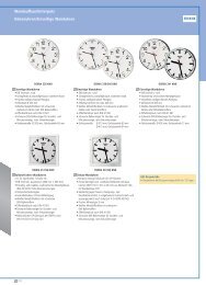
2.2 Exemplary circuit diagrams<br />
Illustration 1: Exemplary circuit diagram BE‐TA5508.01<br />
Design with 8 push buttons<br />
Illustration 2: Exemplary circuit diagram BE‐TA550P8.01<br />
<strong>Plus</strong>‐design with 8 push buttons<br />
<strong>MDT</strong> technologies GmbH • 51766 Engelskirchen • Papiermühle 1<br />
Tel.: +49-2263-880 • Fax: +49-2263-4588 • knx@mdt.de • www.mdt.de
6<br />
<strong>Technical</strong> <strong>Manual</strong> Taster BE-TA55<br />
2.2 Usage & areas of use<br />
The push button contains of almost all of the functions of the binary input. It is designed for flush<br />
mounting. By a pushing a button the push button can call parameterized functions like dimming or<br />
call whole scenes.<br />
The plus variant contains additional of up to 8 bicolored LEDs for the respective buttons and a<br />
bicolored orientation LED and a 4 logic blocks. The LEDS can be parameterized individually.<br />
2.4 Structure & Handling<br />
The push button contains, depending on the design, of 2 to 8 buttons, which can be parameterized<br />
individually. Additional LEDs exists at the plus variant. The bus can be connected at the back of the<br />
push buttons. Furthermore all push buttons contains of the standard elements programming button<br />
and programming LED at the side of the push buttons.<br />
The Illustration shows an 8‐fold push button, at the left a normal one and at the right the plus variant:<br />
Illustration 3: Overview hardware module <strong>Push</strong> Button(left: BE‐TA5508.01; right: BE‐TA55P8.01)<br />
<strong>MDT</strong> technologies GmbH • 51766 Engelskirchen • Papiermühle 1<br />
Tel.: +49-2263-880 • Fax: +49-2263-4588 • knx@mdt.de • www.mdt.de
7<br />
<strong>Technical</strong> <strong>Manual</strong> Taster BE-TA55<br />
The push buttons contains of an invisible cover plate, which is included at the delivery of the push<br />
buttons. This cover plate is for the protection of the labeling. When the labeling was inserted, the<br />
cover plate can be installed. The cover plate has two lugs at every side, which must engage in the<br />
intended executions. For the installation of the cover plate, one side is inserted into the execution.<br />
Now you must curve the cover plate a bit, so the second lug fits into the execution. The cover plate<br />
should be installed with the plain side up.<br />
There are 2 opportunities for the labeling of the push buttons. When the push button is not to be<br />
labeled, a grey insert plate is included, which can be inserted behind the invisible cover plate. If you<br />
want to label the push button, you will find a free pattern in the download section at our homepage<br />
www.mdtautomation.de. This copy pattern can be adapted to your parameterization and inserted<br />
behind the clear cover plate without the grey insert plate.<br />
For dismantling the cover plate, one button is pushed. Now you can lift the cover plate best with a<br />
pointy object. So the cover plate jumps out of its execution and can be removed.<br />
2.5 Functions<br />
The functionality is identical for every channel. The device contains of 2, 4, 6 or 8 buttons based on<br />
the hardware design.<br />
The designation of the channels is always in a consecutive alphabetic order.<br />
There are three possible functionalities for each channel:<br />
Disabled<br />
No function is set to the channel, so this channel does not contain of any communication objects.<br />
Channels grouped<br />
If you select a pair of channel as “channels grouped”, you will be able to parameterize the pair of<br />
channels as dimming‐function, shutter‐function or switching‐ function.<br />
Channels unique<br />
If you select a pair of channels as “channels unique”, you will be able to parameterize each channel<br />
for itself as switch, counter, scene, switch short/long, one button dimming or one button shutter.<br />
At the plus variant, there are additional 4 logic functions (and/or) containing of up to two additional<br />
input objects. Furthermore the plus variant contains of one bicolored LED per channel, which are<br />
individual parameterize able, and one bicolored operating LED.<br />
<strong>MDT</strong> technologies GmbH • 51766 Engelskirchen • Papiermühle 1<br />
Tel.: +49-2263-880 • Fax: +49-2263-4588 • knx@mdt.de • www.mdt.de
8<br />
<strong>Technical</strong> <strong>Manual</strong> Taster BE-TA55<br />
2.5.1 Overview of the functions<br />
General settings Debounce time 10‐120ms, selectable in steps<br />
Time for keystroke long 0,1‐30s, selectable in steps<br />
Limitation of telegrams max. number of telegrams per 10s, can be<br />
parameterized freely<br />
Channels grouped Dimming function brighter/darker function can be assigned to the<br />
channels freely<br />
Shutter function up/down function can be assigned to the<br />
channels freely<br />
Switching function off/on telegrams can be assigned to the<br />
channels freely<br />
Channels unique Switching function switching function<br />
toggle function<br />
status function<br />
time functions<br />
o switch on/off delay<br />
edge evaluation<br />
forced settings<br />
sending of byte‐values<br />
Scene function memory function<br />
selection of different scenes<br />
Switch short/long On‐/Off‐/toggle function<br />
short/long independent parameterize<br />
able<br />
One button dimming steps of dimming<br />
telegram repetition<br />
One button shutter shutter function with only one button<br />
Logic functions<br />
(only at the plus<br />
variant)<br />
Configuration of<br />
LEDs<br />
(only at the plus<br />
variant)<br />
Chart 1: Functional overview push buttons<br />
AND‐function switching function<br />
scene function<br />
inverting<br />
OR‐function switching function<br />
scene function<br />
inverting<br />
Status‐LEDs connections to internal objects possible<br />
connections to external objects<br />
possible<br />
reaction to pushing a button possible<br />
LED display behavior parameterize able<br />
luminescent behavior parameterize<br />
able<br />
LED priority parameterize able(from<br />
hardware version 1.1)<br />
Operating LED on‐/off switchable<br />
controlling with ext. objects possible<br />
Blocking function all LEDs lockable by the blocking object<br />
<strong>MDT</strong> technologies GmbH • 51766 Engelskirchen • Papiermühle 1<br />
Tel.: +49-2263-880 • Fax: +49-2263-4588 • knx@mdt.de • www.mdt.de
9<br />
<strong>Technical</strong> <strong>Manual</strong> Taster BE-TA55<br />
2.6. Settings at the ETS‐Software<br />
Selection at the product database:<br />
Manufacturer: <strong>MDT</strong> Technologies<br />
Product family: <strong>Push</strong> buttons<br />
Product type: <strong>Push</strong> buttons/<strong>Push</strong> buttons plus<br />
Medium Type: Twisted Pair (TP)<br />
Product name: addicted to the used type, e.g.: BE‐TA55P8.01 <strong>Push</strong> button 8‐fold, plus variant<br />
Order number: addicted to the used type, e.g.: BE‐TA55P8.01<br />
The available parameters depend to the chosen product type. The additional functions for the plus<br />
variant are not shown at the normal push buttons.<br />
2.7. Starting up<br />
After wiring the allocation of the physical address and the parameterization of every channel follow:<br />
(1) Connect the interface with the bus, e.g. <strong>MDT</strong> USB interface<br />
(2) set bus power up<br />
(3) Press the programming button at the device(red programming LED lights)<br />
(4) Loading of the physical address out of the ETS‐Software by using the interface(red LED goes<br />
out, as well this process was completed successful)<br />
(5) Loading of the application, with requested parameterization<br />
(6) Switch the power supply on<br />
(7) If the device is enabled you can test the requested functions(also possible by using the ETS‐<br />
Software)<br />
<strong>MDT</strong> technologies GmbH • 51766 Engelskirchen • Papiermühle 1<br />
Tel.: +49-2263-880 • Fax: +49-2263-4588 • knx@mdt.de • www.mdt.de
10<br />
<strong>Technical</strong> <strong>Manual</strong> Taster BE-TA55<br />
3 Communication objects<br />
3.1 Communication objects per channel<br />
The communication objects appear for every channel in dependence of the respective<br />
parameterization. 10 numbers (0‐9, 10‐19,…) for communication objects are automatically assigned<br />
for every pair of channels. The numeration is consecutive, so the channel pair A/B can only have the<br />
numbers from 0 to 9, the same if they parameterized as grouped channels or unique channels. With<br />
every following channel pair the numbers of the objects increase by 10, even if a channel pair is<br />
disabled. If you choose a channel pair as unique, the channel, which is first in the alphabet, will<br />
become the first 5 numbers and the other one will become the following five numbers (e.g. channel<br />
A‐‐>0‐4 and channel B‐‐>5‐9). The numeration of the channels is always the same, even if some<br />
channels are disabled.<br />
At the plus variant, there are additional objects for the LEDs and the logic blocks. The communication<br />
objects for the logic follow on the objects for the channels. There are up to 12 objects for the logic<br />
function, so 12 numbers are reserved for the logic function, e.g. the numbers from 40 to 51 at an 8‐<br />
fold push button. The communication objects for the LEDs start consequently with the first numbers<br />
after the logic blocks. According to the parameterization, one communication object per LED can be<br />
shown. So there are 9 objects at the plus variant of an 8‐fold push button and one blocking object.<br />
The follow<br />
The following illustration shows the communication objects for the channels. Channel A/B is selected<br />
as “channels grouped” and parameterized as a dimming function. The channels C/D are selected as<br />
“channels unique” thus every channel can become an individual function. Channel C is parameterized<br />
as switching‐function and channel D is parameterized as scene‐function. The channels E/F are also<br />
selected as unique channels. Channel E is parameterized as shutter and channel F as switch with the<br />
sub function “send status”. The channels G and H are selected as grouped with a shutter function:<br />
Illustration 4: Communication objects per channel<br />
<strong>MDT</strong> technologies GmbH • 51766 Engelskirchen • Papiermühle 1<br />
Tel.: +49-2263-880 • Fax: +49-2263-4588 • knx@mdt.de • www.mdt.de
11<br />
<strong>Technical</strong> <strong>Manual</strong> Taster BE-TA55<br />
If a channel pair is selected as disabled, no objects will be shown. So there are no opportunities for<br />
programming this channel.<br />
These are the available objects for each channel:<br />
Nr. Function Usage Data type<br />
0 Switch edge control DPT 1.001 Out, Read<br />
0 Send forced setting force control/switch DPT 2.001 Out, Read<br />
0 Shutters down/up driving of shutters DPT 1.008 Out, Read<br />
0 Dimming on/off toggling of the dimming lights DPT 1.001 Out, Read<br />
0 Switch on/off two button switching DPT 1.001 Out, Read<br />
0 Send value sends the parameterized value DPT 5.001 Out, Read<br />
0 push‐button short sends action for short keystroke DPT 1.001 Out, Read<br />
1 Value for toggle edge control with toggle function DPT 1.001 In, Write<br />
1 Stop/Blinds open/close driving of the blinds/ stopping<br />
movement of the shutters<br />
DPT 1.009 Out, Read<br />
1 Dimming dimming DPT 3.007 Out, Read<br />
2 Scene scene control DPT 18.001 Out, Read<br />
0 push‐button long sends action for long keystroke DPT 1.001 Ѐut, Read<br />
4 Blocking object blocks the related channel DPT 1.001 In, Write<br />
+5 next channel<br />
Chart 2: communication objects per channel<br />
3.2 Communication objects logic<br />
only at the plus variant<br />
There are communication objects for the logic function at every push button additional to the<br />
communication objects per channel. These objects can be parameterized and shown independent<br />
from the parameterization of the channels. The logic objects have the numbers from 80 at a 16‐fold<br />
push button and the numbers from 40 at an 8‐fold push button. The first logic block gets assigned<br />
the first three numbers, so at an 8‐fold push button from 40 to 42. Every following block increases<br />
the numbers by 3.<br />
The addressing can be made by using the communication objects for the logic analogous to the<br />
addressing by the channels.<br />
The following communication objects for the logic can be shown:<br />
Illustration 5: communication objects logic<br />
If a logic block is disabled, no communication objects will be shown. Therefore no addressing is<br />
possible. Every push button contains of 4 logic blocks for which the following objects can be shown:<br />
Nr. Function Usage Data type<br />
40/80 Logic input 1 A Logic input DPT 1.001 In, Write<br />
41/81 Logic input 1 B Logic input DPT 1.001 In, Write<br />
42/82 Logic output 1 Logic output DPT 1.001 Out, Read<br />
42/82 Logic output 1 scene Logic output scene DPT 18.001 Out, Read<br />
+3 next logic block<br />
Chart 3: communication objects logic<br />
<strong>MDT</strong> technologies GmbH • 51766 Engelskirchen • Papiermühle 1<br />
Tel.: +49-2263-880 • Fax: +49-2263-4588 • knx@mdt.de • www.mdt.de
12<br />
<strong>Technical</strong> <strong>Manual</strong> Taster BE-TA55<br />
3.3 Communication objects LED<br />
only at the plus variant<br />
The available LEDs can be controlled by different methods. According to the method, one<br />
communication object can be shown for every LED, which afterwards can be connected to the group<br />
addresses in any way. So there are up to 9 communication objects available at the 8‐fold push button.<br />
There is additional one blocking object for the LEDs and two objects for the priority of the LEDs.<br />
The following illustration shows the communication objects, which can be shown:<br />
Illustration 6: Communication objects LEDs<br />
The following communication objects are available:<br />
Nr. Function Usage Data type<br />
22/32/ LED 1 switch LED DPT 1.001 In, Write, Out<br />
42/52<br />
Read<br />
+1 next LED<br />
30/40/ LED orientation light switch LED DPT 1.001 In, Write, Out,<br />
50/60<br />
Read<br />
31/41/ LED blocking object block all LEDs DPT 1.001 In, Write, Out,<br />
51/61<br />
Read<br />
32/42/ LED priority 1* switch priority 1 DPT 1.001 In, Write, Out,<br />
52/62<br />
Read<br />
33/43/ LED priority 2* switch priority 1 DPT 1.001 In, Write, Out,<br />
53/63<br />
Read<br />
Chart 4: Communication objects LEDs<br />
*=from hardware version 1.1<br />
<strong>MDT</strong> technologies GmbH • 51766 Engelskirchen • Papiermühle 1<br />
Tel.: +49-2263-880 • Fax: +49-2263-4588 • knx@mdt.de • www.mdt.de
13<br />
<strong>Technical</strong> <strong>Manual</strong> Taster BE-TA55<br />
3.4 Default settings of the communication objects<br />
The following chart shows the default settings for the communication objects:<br />
Default settings<br />
Nr. Button Function Length Priority C R W T U<br />
0 Button 1 Switch 1 Bit Low X X X<br />
0 Button 1 Shutter 1 Bit Low X X X<br />
0 Button 1 Send value 1 Byte Low X X X<br />
0 Button 1 Dimming on/off 1 Bit Low X X X<br />
0 Button 1 push‐button short 1 Bit Low X X X<br />
0 Button 1 Send forced setting 2 Bit Low X X X<br />
0 <strong>Buttons</strong> 1/2 Switch on/off 1 Bit Low X X X<br />
0 <strong>Buttons</strong> 1/2 Dimming on/off 1 Bit Low X X X<br />
0 <strong>Buttons</strong> 1/2 Shutter down/up 1 Bit Low X X X<br />
1 Button 1 Value for toggle 1 Bit Low X X X<br />
1 Button 1 Stop/Blinds open/close 1 Bit Low X X X<br />
1 Button 1 Dimming 4 Bit Low X X X<br />
1 <strong>Buttons</strong> 1/2 Dimming 4 Bit Low X X X<br />
1 <strong>Buttons</strong> 1/2 Stop/Blinds open/close 1 Bit Low X X X<br />
2 Button 1 Scene 1 Byte Low X X X<br />
2 Button 1 Value for toggle 1 Bit Low X X X X<br />
2 Button 1 <strong>Push</strong>‐button long 1 Bit Low X X X<br />
4 Button 1 Blocking object 1 Bit Low X X X<br />
10/20/30/40 Logic input 1 A Logic input 1 A 1 Bit Low X X X<br />
11/21/31/41 Logic input 1 B Logic input 1 B 1 Bit Low X X X<br />
12/22/32/42 Logic output 1 Logic output 1 1 Bit Low X X X<br />
12/22/32/42 Logic output 1 scene Logic output 1 scene 1 Byte Low X X X<br />
22/32/42/52 LED 1* LED switch 1 Bit Low X X X X X<br />
30/40/50/60 LED orientation<br />
light*<br />
LED switch 1 Bit Low X X X X X<br />
31/41/51/61 LED blocking object* block all LEDs 1 Bit Low X X X X X<br />
32/42/52/62 LED priority 1** switch priority 1 1 Bit Low X X X X<br />
33/43/53/63 LED priority 2** switch priority 1 1 Bit Low X X X X<br />
Chart 5: Communication objects – default settings<br />
You can see the default values for the communication objects from the upper chart. According to<br />
requirements the priority of the particular communication objects as well as the flags can be<br />
adjusted by the user. The flags allocates the function of the objects in the programming thereby<br />
stands C for communication, R for Read, W for write, T for transmit and U for update.<br />
*= only at the plus variant<br />
**=from hardware version 1.1<br />
<strong>MDT</strong> technologies GmbH • 51766 Engelskirchen • Papiermühle 1<br />
Tel.: +49-2263-880 • Fax: +49-2263-4588 • knx@mdt.de • www.mdt.de
14<br />
<strong>Technical</strong> <strong>Manual</strong> Taster BE-TA55<br />
4 Reference ETS‐Parameter<br />
4.1 General Settings<br />
The following parameters exist once and affect all channels:<br />
Illustration 7: General settings<br />
The following chart shows the dynamic range for the general settings:<br />
ETS‐text Dynamic range<br />
[default value]<br />
Time for keystroke long 0,1‐30 sec<br />
[0.8 sec]<br />
Limitation of telegrams Inactive<br />
Active<br />
max quantity in 10 seconds 1‐255<br />
[15]<br />
Behavior at bus power up No read value for toggle<br />
Read value for toggle<br />
Chart 6: General settings<br />
<strong>MDT</strong> technologies GmbH • 51766 Engelskirchen • Papiermühle 1<br />
Tel.: +49-2263-880 • Fax: +49-2263-4588 • knx@mdt.de • www.mdt.de<br />
comment<br />
releases the time when the ETS<br />
recognizes a long keystroke<br />
activates/deactivates the limitation of<br />
telegrams<br />
max number of telegrams per 10<br />
seconds (appears only if the limitation<br />
of telegrams is activated)<br />
activates the reading of the value for<br />
toggle at bus power up
15<br />
<strong>Technical</strong> <strong>Manual</strong> Taster BE-TA55<br />
1. All push buttons have a fixed debouncing time, which cannot be changed by the user. The<br />
debounce time is adjusted in‐plant to the push buttons.<br />
1. The parameter “Time for keystroke long” allocates a static value to the push button from<br />
when a long keystroke is recognized. This parameter is important for functions, which have<br />
different functions for a long and a short keystroke.<br />
2. The limitation of telegrams can achieve that the bus gets not overloaded. An overloading<br />
of the bus‐system can cause long waiting periods, e.g. at pushing a button. If the limitation<br />
of telegrams is activated and more telegrams than allowed are send, the telegrams above<br />
the limitation will be send at the next time interval. Therefore an overload of the bus can<br />
be prevented.<br />
3. The parameter “Behavior at bus power up” defines the behavior of the push button at a<br />
bus power return. The setting “Read value for toggle” effects that all communication<br />
objects “value for toggle” are read. So the push button knows the current status of the<br />
objects. If you choose the setting “no read value for toggle”, the push button will not know<br />
the current status of the actor. So the push button assumes an unconfirmed value for the<br />
objects “value for toggle” and sends always a “0”‐signal at the next operation. Only now<br />
the push button knows the status of the actor and can send the right values. But if you<br />
choose the read of these values at a bus power up, the push button will send immediately<br />
the right value for toggling.<br />
<strong>MDT</strong> technologies GmbH • 51766 Engelskirchen • Papiermühle 1<br />
Tel.: +49-2263-880 • Fax: +49-2263-4588 • knx@mdt.de • www.mdt.de
16<br />
<strong>Technical</strong> <strong>Manual</strong> Taster BE-TA55<br />
4.2 Configuration<br />
Setting of the functionality of the channels:<br />
Illustration 8: Usage of the buttons<br />
ETS‐text Dynamic range<br />
[default value]<br />
Function Button A/B –[O/P] disabled<br />
Channels grouped<br />
Channels unique<br />
Chart 7: Parameter channel‐configuration<br />
<strong>MDT</strong> technologies GmbH • 51766 Engelskirchen • Papiermühle 1<br />
Tel.: +49-2263-880 • Fax: +49-2263-4588 • knx@mdt.de • www.mdt.de<br />
comment<br />
Operating mode of the<br />
channels<br />
There are 3 different operating modes for every button( have a look at chart 7). The followig options<br />
to parameterize the channels are dependent to the choosen operating mode. If you disable the<br />
channel, there will be no options to parameterize this channel.
17<br />
<strong>Technical</strong> <strong>Manual</strong> Taster BE-TA55<br />
4.3 Identical parameter<br />
4.3.1 Blocking object<br />
As well for grouped channels as for unique channels the blocking object can be activated. At the<br />
unique channels one blocking object for every channel can be activated. For grouped channels, you<br />
can activate one blocking object for both channels. The communication object for a channel appears<br />
as soon as it is activated for a channel. So there are up to 8 blocking objects parameterize able at a 8‐<br />
fold push button. The corresponding channel of the blocking object is blocked by sending a logical 1.<br />
A blocked channel is not controllable as long as it is blocked. By sending a logical 0, the channel can<br />
be unblocked again.<br />
Number Name Length Usage<br />
4 Blocking object 1 Bit blocks the related channel by sending a logical 1<br />
Chart 8: Communication object blocking object<br />
4.4 Parameter Channels grouped<br />
The chart shows the setting options for grouped channels:<br />
ETS‐text Dynamic range<br />
[default value]<br />
Button A/B Dimming<br />
Shutter<br />
Switch<br />
Dimming function A/B Brighter/Darker<br />
Darker/Brighter<br />
Shutter function A/B Up/Down<br />
Down/Up<br />
Switch function A/B On/Off<br />
Off/On<br />
Blocking Object Inactive<br />
Active<br />
Chart 9: Parameter Channels grouped<br />
<strong>MDT</strong> technologies GmbH • 51766 Engelskirchen • Papiermühle 1<br />
Tel.: +49-2263-880 • Fax: +49-2263-4588 • knx@mdt.de • www.mdt.de<br />
comment<br />
Operating mode of the channel<br />
Defines which channel should<br />
dim up and which should dim<br />
down<br />
Defines which channel should<br />
drive the shutter a down and<br />
which up<br />
Defines which channel should<br />
switch off and which on<br />
The blocking object can be<br />
displayed for every pair of<br />
channels<br />
By choosing channels as grouped, two channels become one common function. The grouped<br />
function is called dual surface, like dual surface dimming, and dual surface shutter. In contrast to the<br />
single surface functions, one action can be performed independent form the other one. One input<br />
performs always one function. The assignment for the buttons can be made individually, so it is<br />
possible to configure which button should for example drive the shutters up and which down.
18<br />
<strong>Technical</strong> <strong>Manual</strong> Taster BE-TA55<br />
4.4.1 Dimming<br />
The dual surface dimming function (channels grouped) is for controlling dimming actuators by start‐<br />
stop dimming commands.<br />
The following parameters are visible, when a pair of channels is chosen as dimming‐function:<br />
Illustration 9: Parameter dual surface dimming<br />
Number Name Length Usage<br />
0 Dimming on/off 1 Bit Switching function of the dimming process;<br />
action for a short keystroke<br />
1 Dimming 4 Bit Dimming function; action for a long keystroke<br />
Chart 10: Communication objects dual surface dimming<br />
When a pair of channels is parameterized as dimming function, two objects are shown. One object<br />
reacts to a short keystroke, the switching object “Dimming on/off”, and the other object reacts to a<br />
long keystroke, the dimming object “dimming”.<br />
It is possible to parameterize this function as brighter/darker or as darker/brighter. The first function<br />
belongs always to the first button. If you switch this parameter, the function will be switched<br />
automatically.<br />
By choosing the dimming function (channel A/B) as brighter/darker, the function reacts in this way:<br />
A short keystroke at button A switches the lights on. The lights are switched off by a short keystroke<br />
at button B. A long keystroke dims the lights step by step until releasing the long keystroke. The lights<br />
are dimmed brighter at button A and darker at button B. The push button starts always with the last<br />
brightness level, before switching off.<br />
The step size is set fixed to 100% at the dual surface dimming. It is a start‐stop dimming. that means<br />
the lights are dimmed as long as you hold the button. After releasing the button a stop value is sent,<br />
which stops the dimming process. So you can dim the lights with only one keystroke from 0% to<br />
100% or from 100% to 0%, by pushing the button long enough.<br />
<strong>MDT</strong> technologies GmbH • 51766 Engelskirchen • Papiermühle 1<br />
Tel.: +49-2263-880 • Fax: +49-2263-4588 • knx@mdt.de • www.mdt.de
19<br />
<strong>Technical</strong> <strong>Manual</strong> Taster BE-TA55<br />
The chart shows the correlations between the dimming‐ and the switching‐object:<br />
Function Brighter/Darker Function Darker/Brighter<br />
Button Button A Button B Button A Button B<br />
Dimming function Brighter Darker Darker Brighter<br />
Switching function On Off Off On<br />
Chart 11: Dimming function<br />
The following diagram shows the dual surface dimming function:<br />
<strong>MDT</strong> technologies GmbH • 51766 Engelskirchen • Papiermühle 1<br />
Tel.: +49-2263-880 • Fax: +49-2263-4588 • knx@mdt.de • www.mdt.de
20<br />
<strong>Technical</strong> <strong>Manual</strong> Taster BE-TA55<br />
4.4.2 Shutter<br />
The dual surface shutter‐function triggers shutter actuators, which can drive shutter and blinds.<br />
The following parameters are shown, when a pair of channel is adjusted as shutter function:<br />
Illustration 10: dual surface shutter function<br />
Number Name Length Usage<br />
0 Shutter Down/Up 1 Bit Driving function for the shutters, action for a<br />
long keystroke<br />
1 Stop/Blinds Open/Close 1 Bit Stop/Adjustment of the blinds, action for a<br />
short keystroke<br />
Chart 12: Communication objects dual surface shutter function<br />
If you choose a pair of channels as shutter function, two communication objects will appear for this<br />
pair of channel. On the one hand the stop/blind adjustment object called “Stop/Blinds Open/Close”,<br />
which responds to a short keystroke and on the other hand the driving object called “Shutter<br />
Down/Up”, which responds to a long keystroke.<br />
The driving object is for moving the shutters up and down. The stop‐/blind adjustment object is for<br />
the adjustment of the blinds and additional it stops a running movement of the shutter.<br />
Every shutter actuator controls with a 0‐signal the up‐movement and with a 1‐signal the down<br />
movement. So the push button sends these signals to the corresponding driving commands.<br />
The Chart shows the correlations between the Stop‐/Blind adjustment object and the driving object<br />
for the individual channels:<br />
Function Down/Up Function Up/Down<br />
Button Button A Button B Button A Button B<br />
Stop‐/Blind<br />
adjustment object<br />
Down Up Up Down<br />
Driving object Stop/close blinds Stop/open blinds Stop/open blinds Stop/close blinds<br />
Chart 13: shutter function<br />
<strong>MDT</strong> technologies GmbH • 51766 Engelskirchen • Papiermühle 1<br />
Tel.: +49-2263-880 • Fax: +49-2263-4588 • knx@mdt.de • www.mdt.de
21<br />
<strong>Technical</strong> <strong>Manual</strong> Taster BE-TA55<br />
4.4.3 Switch<br />
The values for on and off can be assigned freely at the switching function for the grouped channels.<br />
If you adjust a pair of channel as switch, the following parameters will be shown:<br />
Illustration 11: dual surface switching function<br />
Simple functions, like an alternating circuit, can be programmed easily by using the grouped switch<br />
function. The 1 bit communication object sends in dependence of the parameterization a 0‐ or a 1‐<br />
signal for the first button and the inverted signal for the second channel. So you can chose which<br />
channel should switch off and which should switch on.<br />
The following chart shows the corresponding communication object:<br />
Number Name Length Usage<br />
0 Switch On/Off 1 Bit Switching object for the dual surface switching<br />
function<br />
Chart 14: Communication object dual surface switching function<br />
<strong>MDT</strong> technologies GmbH • 51766 Engelskirchen • Papiermühle 1<br />
Tel.: +49-2263-880 • Fax: +49-2263-4588 • knx@mdt.de • www.mdt.de
22<br />
<strong>Technical</strong> <strong>Manual</strong> Taster BE-TA55<br />
4.5 Parameters channels unique<br />
There are 6 different operating modes for the unique channels, which can be adjusted for each<br />
channel:<br />
Inactive<br />
Switch<br />
Scene<br />
Switch short/long<br />
One button dimming<br />
One button shutter<br />
After the assignment of the operating mode the further parameterization can be done. If the channel<br />
is selected as inactive, no further parameterization will be possible.<br />
4.5.1 Switch<br />
The switching function is for switching the corresponding output on, off and toggling it. There is a<br />
multitude of sub‐functions at the switching function, which enables the user to evaluate edges and<br />
integrate times to the switching process.<br />
The following parameters are shown, when the channel is selected as switch:<br />
Illustration 12: Parameter switch<br />
Various sub‐functions are available at a switching output. Most of these sub‐functions contain also of<br />
further parameterization‐options. The different sub‐functions as well as their parameterization‐<br />
options are described in the following segments:<br />
<strong>MDT</strong> technologies GmbH • 51766 Engelskirchen • Papiermühle 1<br />
Tel.: +49-2263-880 • Fax: +49-2263-4588 • knx@mdt.de • www.mdt.de
23<br />
<strong>Technical</strong> <strong>Manual</strong> Taster BE-TA55<br />
4.5.1.1 Switch falling/rising edge<br />
The following setting options are available, when the sub‐function switch falling/rising edge was<br />
adjusted:<br />
ETS‐text Dynamic range<br />
[default value]<br />
comment<br />
Value for rising/falling edge On<br />
switches on/off at a<br />
Off<br />
falling/rising edge<br />
Chart 15: Parameter switch rising/falling edge<br />
The sub‐function “switch rising edge” or “switch falling edge” sends only a signal at the adjusted<br />
edge. You can parameterize whether a 0‐signal or a 1‐signal should be sent. There is no inverted<br />
signal at subsiding the edge. This function always sends only one adjusted signal.<br />
The following diagram shows this sub‐function for rising edges. As soon as the state changes from 0<br />
to 1, the push button sends an On‐pulse (=1‐signal):<br />
The following chart shows the corresponding communication object:<br />
Number Name Length Usage<br />
0 Switch 1 Bit Switching function, no differences between a<br />
long and a short keystroke<br />
Chart 16: Communication object switch rising/falling edge<br />
<strong>MDT</strong> technologies GmbH • 51766 Engelskirchen • Papiermühle 1<br />
Tel.: +49-2263-880 • Fax: +49-2263-4588 • knx@mdt.de • www.mdt.de
24<br />
<strong>Technical</strong> <strong>Manual</strong> Taster BE-TA55<br />
4.5.1.2 Toggle rising/falling edge<br />
The sub‐function “toggle rising edge“ or “toggle falling edge” toggles at the adjusted edge. That<br />
means, the current value of the communication object is inverted at every switching process. By<br />
using this function an edge based alternating circuit can be realized.<br />
The following diagram describes this sub‐function. As soon as the state changes from 1 to 0, the push<br />
button sends the inverted signal. The signal is send always as a short pulse:<br />
The following chart shows the corresponding communication objects:<br />
Number Name Length Usage<br />
0 Switch 1 Bit Switching function; no differences between<br />
long and short keystroke<br />
1 Value for toggle 1 Bit status object, indicates the switching state of<br />
the channel<br />
Chart 17: Communication objects toggle rising/falling edge<br />
<strong>MDT</strong> technologies GmbH • 51766 Engelskirchen • Papiermühle 1<br />
Tel.: +49-2263-880 • Fax: +49-2263-4588 • knx@mdt.de • www.mdt.de
25<br />
<strong>Technical</strong> <strong>Manual</strong> Taster BE-TA55<br />
To be sure that the push button toggles at every switching process, you have to connect the status<br />
object of the push button “Value for toggle” with the status object of the actuator. When the push<br />
button should work without an actuator, the object has to be connected to the switching object<br />
“switch”. The connection is important, because the push button cannot invert the signal, when it<br />
does not know its current state.<br />
By undocking this communication object, you have more choices to program the push button. So you<br />
can use the object “Value for toggle” for visualizations or additional functions and you will be more<br />
free in design your project.<br />
So you have for example the option to visualize the switching process by connecting the status‐object<br />
to a switching object of a LED or something else.<br />
<strong>MDT</strong> technologies GmbH • 51766 Engelskirchen • Papiermühle 1<br />
Tel.: +49-2263-880 • Fax: +49-2263-4588 • knx@mdt.de • www.mdt.de
26<br />
<strong>Technical</strong> <strong>Manual</strong> Taster BE-TA55<br />
4.5.1.3 Send Status<br />
By using the sub‐function „Send status“ the push button sends always the parameterized signal for<br />
the corresponding edge. The following window is shown for the sub‐function “Send status”:<br />
Illustration 13: Sub‐function send status<br />
These settings are available:<br />
ETS‐text Dynamic range<br />
[default value]<br />
Value for rising edge On<br />
Off<br />
Value for falling edge On<br />
Off<br />
Chart 18: Parameter Send status<br />
<strong>MDT</strong> technologies GmbH • 51766 Engelskirchen • Papiermühle 1<br />
Tel.: +49-2263-880 • Fax: +49-2263-4588 • knx@mdt.de • www.mdt.de<br />
comment<br />
The corresponding communication object is shown at the following chart:<br />
switches on/off at a rising edge<br />
switches on/off at a falling edge<br />
Number Name Length Usage<br />
0 Switch 1 Bit Switching function; no differences between<br />
long and short keystroke<br />
Chart 19: Communication object send status
27<br />
<strong>Technical</strong> <strong>Manual</strong> Taster BE-TA55<br />
The parameter “Value for rising edge“ defines whether the channel should send an 1‐signal (value:<br />
On) or a 0‐signal (value: Off). If you want for example switch a channel of a switch actuator, you will<br />
have to choose different values for the rising and the falling edge. Otherwise the push button sends<br />
the same signal twice, for example an On‐signal.<br />
The cyclic sending causes that the state of the push button is sent periodically in certain<br />
parameterize able intervals. Then the push button sends the parameterized value for the<br />
corresponding edge.<br />
A common application for this parameter is for example the observation of windows, which are<br />
equipped with window‐contacts. So a display can for example show whether all windows are closed<br />
or not. Furthermore an alarm device can operate with this function.<br />
The following diagram describes this sub‐function. In this example, the push button sends a 1‐signal<br />
for a falling edge and a 0‐signal for a rising edge. Additional the diagram shows the connection with a<br />
switch actuator, which was parameterized with a normal switching function:<br />
<strong>MDT</strong> technologies GmbH • 51766 Engelskirchen • Papiermühle 1<br />
Tel.: +49-2263-880 • Fax: +49-2263-4588 • knx@mdt.de • www.mdt.de
28<br />
<strong>Technical</strong> <strong>Manual</strong> Taster BE-TA55<br />
4.5.1.4 Send Value rising/falling/both edges<br />
There are two further sub‐functions at the sub‐function Send Value. On the one hand you can send 1<br />
Byte Values and on the other hand you can activate a forced setting (2 Bit). These functions can be<br />
parameterized according to your wishes.<br />
The following illustration shows this parameter:<br />
Illustration 14: Sub‐function send value<br />
After activating the sub function „Send value“, you have to choose which values should be sent. The<br />
setting options are shown at the chart:<br />
ETS‐text Dynamic range<br />
[default value]<br />
comment<br />
Value (1 Byte)/ forced<br />
1 Byte Value<br />
Choice between 1 Byte‐ and 2<br />
setting(2 Bit)<br />
2 Bit Value(forced setting) Bit‐Value<br />
Chart 20: Parameter send value<br />
If you have activated the setting “1 Byte”, the following settings are possible:<br />
ETS‐text Dynamic range<br />
[default value]<br />
comment<br />
Value for rising/falling edge 0‐255<br />
Assignment, which value<br />
[0]<br />
should be send for the<br />
falling/rising edge<br />
Chart 21: Parameter send value, 1 Byte object<br />
The 1 Byte communication object can send any value in its dynamic range at both edges. The<br />
dynamic range is thereby from 0‐255. Depending on parameterization the push button sends the<br />
adjusted values for the rising or the falling edge or for both edges.<br />
The following chart shows the according communication object:<br />
Number Name Length Usage<br />
0 Send value 1 Byte sends the parameterized value<br />
Chart 22: Communication object Parameter Send value‐1 Byte object<br />
<strong>MDT</strong> technologies GmbH • 51766 Engelskirchen • Papiermühle 1<br />
Tel.: +49-2263-880 • Fax: +49-2263-4588 • knx@mdt.de • www.mdt.de
29<br />
<strong>Technical</strong> <strong>Manual</strong> Taster BE-TA55<br />
The setting option 2 Bit value (forced setting) has the following options to parameterize this function:<br />
ETS‐text Dynamic range<br />
[default value]<br />
comment<br />
Send forced setting at<br />
Forced setting not active Assignment, which forced<br />
rising/falling edge<br />
Forced setting off setting should be send at which<br />
Forced setting on edge<br />
Chart 23: Dynamic range send value‐forced setting<br />
The forced setting object allows for example to control the automatic brightness control of presence<br />
detectors.<br />
The forced setting object can send 3 different states:<br />
Forced setting not active (control=0; value=0)<br />
The forced setting object has no influence on the receiver. For example at a presence<br />
detector, the automatic function (motion detector operation) would be switched on.<br />
Forced setting off (control=1; value=0)<br />
The forced setting object switches the receiver unconditionally off. For example a presence<br />
detector, would be switched permanent off. Detected motions have no influence on the<br />
output.<br />
Forced setting on (control=1, value=1)<br />
The forced setting object switches the receiver unconditionally on. For example a presence<br />
detector, would be switched permanent on. Detected motions have no influence on the<br />
output.<br />
The according communication object is shown at the chart:<br />
Number Name Length Usage<br />
0 Send forced setting 2 Bit sends the adjusted forced setting<br />
Chart 24: Communication object Send value‐forced setting<br />
<strong>MDT</strong> technologies GmbH • 51766 Engelskirchen • Papiermühle 1<br />
Tel.: +49-2263-880 • Fax: +49-2263-4588 • knx@mdt.de • www.mdt.de
30<br />
<strong>Technical</strong> <strong>Manual</strong> Taster BE-TA55<br />
4.5.1.5 Send value with on/off delay<br />
The following setting options are available at the function “Send value with on/off delay”:<br />
ETS‐text Dynamic range<br />
[default value]<br />
comment<br />
Delay time 0‐60min<br />
Adjustment of the delay time<br />
[1s]<br />
for the sending process<br />
Chart 25: Parameter Send value with delay<br />
The sub‐function “Send value with on/off delay” allows that the push button sends its value after a<br />
parameterized time. At the on‐delay, the time starts when the associated button was switched on<br />
and at the off‐delay, the time starts when the associated button was switched off. The push button<br />
sends always its current value at this function. If the value changes before the time ran out, the on‐<br />
delay will expire. For example, when an input with a parameterized on‐delay is switched off, before it<br />
was switched on, the input remains off.<br />
The following diagram describes the sub‐function „Send value with on‐delay“:<br />
<strong>MDT</strong> technologies GmbH • 51766 Engelskirchen • Papiermühle 1<br />
Tel.: +49-2263-880 • Fax: +49-2263-4588 • knx@mdt.de • www.mdt.de
31<br />
<strong>Technical</strong> <strong>Manual</strong> Taster BE-TA55<br />
You can see the adjusted settings, which were made in the ETS for this setting:<br />
Illustration 15: Send value with on‐delay<br />
The following chart shows the communication object:<br />
Number Name Length Usage<br />
0 Switch 1 Bit Switching function; no differences between<br />
long and short keystroke<br />
Chart 26: Communication object send value with delay<br />
<strong>MDT</strong> technologies GmbH • 51766 Engelskirchen • Papiermühle 1<br />
Tel.: +49-2263-880 • Fax: +49-2263-4588 • knx@mdt.de • www.mdt.de
32<br />
<strong>Technical</strong> <strong>Manual</strong> Taster BE-TA55<br />
4.5.2 Scene<br />
The scene function calls scenes, which are saved in actuators. Scene numbers in the push button and<br />
the actuators must be identical. It is possible to save scenes by a long keystroke if the saving function<br />
was activated.<br />
The following illustration shows the setting options for this parameter:<br />
Illustration 16: Parameter Scene<br />
The following chart shows the dynamic range of this parameter:<br />
Sub‐function Dynamic range<br />
[default value]<br />
Saving function No save<br />
Save<br />
Scene number 1‐64<br />
[1]<br />
Blocking object Inactive<br />
Active<br />
Chart 27: sub‐function scene<br />
<strong>MDT</strong> technologies GmbH • 51766 Engelskirchen • Papiermühle 1<br />
Tel.: +49-2263-880 • Fax: +49-2263-4588 • knx@mdt.de • www.mdt.de<br />
comment<br />
The chart shows the communication objects for this parameter:<br />
Number Name Length Usage<br />
2 Scene 1 Byte calls the depending scene<br />
Chart 28: Communication object Parameter scene<br />
Saving function is selected ba a<br />
long keystroke<br />
Scene number must be<br />
identical with the one in the<br />
actuators<br />
have a look at 4.3.1 blocking<br />
object<br />
The scene function calls scenes, which were stored in actuators. Scenes contain of parameterized<br />
states of several actuators, which can be called with only one keystroke by using the scene function.<br />
Additional to the call of scenes, scenes can be saved at the call of a push button by a long keystroke.<br />
When the saving function was activated, a long keystroke at the push button saves the current state<br />
of the actuators to the depending scene.
33<br />
<strong>Technical</strong> <strong>Manual</strong> Taster BE-TA55<br />
For calling a scene or saving a new value for the scene, you have to send the accordingly code to the<br />
relevant communication object for the scene:<br />
Scene Retrieve Save<br />
Hex. Dez. Hex. Dez.<br />
1 0x00 0 0x80 128<br />
2 0x01 1 0x81 129<br />
3 0x02 2 0x82 130<br />
4 0x03 3 0x83 131<br />
5 0x04 4 0x84 132<br />
6 0x05 5 0x85 133<br />
7 0x06 6 0x86 134<br />
8 0x07 7 0x87 135<br />
9 0x08 8 0x88 136<br />
10 0x09 9 0x89 137<br />
11 0x0A 10 0x8A 138<br />
12 0x0B 11 0x8B 139<br />
13 0x0C 12 0x8C 140<br />
14 0x0D 13 0x8D 141<br />
15 0x0E 14 0x8E 142<br />
16 0x0F 15 0x8F 143<br />
17 0x10 16 0x90 144<br />
18 0x11 17 0x91 145<br />
19 0x12 18 0x92 146<br />
20 0x13 19 0x93 147<br />
21 0x14 20 0x94 148<br />
22 0x15 21 0x95 149<br />
23 0x16 22 0x96 150<br />
24 0x17 23 0x97 151<br />
25 0x18 24 0x98 152<br />
26 0x19 25 0x99 153<br />
27 0x1A 26 0x9A 154<br />
28 0x1B 27 0x9B 155<br />
29 0x1C 28 0x9C 156<br />
30 0x1D 29 0x9D 157<br />
31 0x1E 30 0x9E 158<br />
32 0x1F 31 0x9F 159<br />
Chart 29: Calling and saving scenes<br />
<strong>MDT</strong> technologies GmbH • 51766 Engelskirchen • Papiermühle 1<br />
Tel.: +49-2263-880 • Fax: +49-2263-4588 • knx@mdt.de • www.mdt.de
34<br />
<strong>Technical</strong> <strong>Manual</strong> Taster BE-TA55<br />
4.5.3 Switch short/long<br />
The parameter switch short/long can assign the push button different switching processes for a long<br />
and a short keystroke.<br />
The following illustration shows the sub‐functions for this parameter:<br />
Illustration 17: Parameter switch short/long<br />
The sub‐functions for this parameter are shown in the chart below:<br />
Sub‐function Dynamic range<br />
[default value]<br />
comment<br />
Value for keystroke short ‐ On<br />
Action for a short keystroke<br />
Object 1<br />
Off<br />
Toggle<br />
Nothing<br />
Value for keystroke long ‐ On<br />
Action for a long keystroke<br />
Object 2<br />
Off<br />
Toggle<br />
Nothing<br />
Blocking object Inactive<br />
have a look at 4.3.1 blocking<br />
Active<br />
object<br />
Chart 30: Sub‐functions parameter switch short/long<br />
The chart shows the associated communication objects:<br />
Number Name Length Usage<br />
0 push‐button short 1 Bit Switching function short keystroke<br />
2 push‐button long 1 Bit Switching function long keystroke<br />
Chart 31: Communication object parameter switch short/long<br />
<strong>MDT</strong> technologies GmbH • 51766 Engelskirchen • Papiermühle 1<br />
Tel.: +49-2263-880 • Fax: +49-2263-4588 • knx@mdt.de • www.mdt.de
35<br />
<strong>Technical</strong> <strong>Manual</strong> Taster BE-TA55<br />
The parameter “switch short/long” can control for example two channels of an actuator by using only<br />
one button. Furthermore you can switch a channel with a long keystroke on and with a short<br />
keystroke off. For both objects, a function can be set individually. Therefore the sub‐functions on, off,<br />
toggle and nothing are available. Two communication objects are displayed, which can be connected<br />
in any way. By activating the sub‐function “toggle” an additional communication object appears,<br />
called “value for toggling”. This object is a status object for the push button and must be connected<br />
to the status‐object of the actuator (have a look at: 4.5.1 Toggle)<br />
The following diagram shows the behavior of this parameter. Both objects (push‐button and push‐<br />
button long) were set to toggle. The object for the long keystroke is connected to channel A of the<br />
switch actuator and the object for the short keystroke is connected to channel B:<br />
In this example the push button toggles Channel B with a short keystroke. The Channel A does not<br />
react to a short keystroke. This one reacts only at a long keystroke with toggling.<br />
<strong>MDT</strong> technologies GmbH • 51766 Engelskirchen • Papiermühle 1<br />
Tel.: +49-2263-880 • Fax: +49-2263-4588 • knx@mdt.de • www.mdt.de
36<br />
<strong>Technical</strong> <strong>Manual</strong> Taster BE-TA55<br />
The following diagram shows a further application example for this parameter. In this example, the<br />
object for a long keystroke switches the channel A of a switch actuator on. A short keystroke<br />
switches the channel off. The three communication objects were connected in only one group<br />
address:<br />
<strong>MDT</strong> technologies GmbH • 51766 Engelskirchen • Papiermühle 1<br />
Tel.: +49-2263-880 • Fax: +49-2263-4588 • knx@mdt.de • www.mdt.de
37<br />
<strong>Technical</strong> <strong>Manual</strong> Taster BE-TA55<br />
4.5.4 One button Dimming<br />
The dimming function for the unique channels, often called one surface dimming, performs the<br />
dimming process only by one channel.<br />
Illustration 18: Parameter one surface dimming<br />
The possible settings for this parameter are shown in the chart below:<br />
Sub‐function Dynamic range<br />
[default value]<br />
comment<br />
Dimming steps 100%<br />
The dimming steps specify how<br />
50%<br />
much should be dimmed by one<br />
25%<br />
dimming process.<br />
12,5%<br />
3%<br />
1,5%<br />
Repeat telegrams No<br />
switches the repeating of the<br />
Yes<br />
dimming telegram on/off<br />
Repetition time 0,3s<br />
This parameter is only shown,<br />
0,5s<br />
when the repetition of telegrams<br />
0,7s<br />
was activated.<br />
1,0s<br />
1,3s<br />
1,5s<br />
2,0s<br />
5,0s<br />
Blocking object Inactive<br />
have a look at 4.3.1 blocking<br />
Active<br />
object<br />
Chart 32: Sub‐functions one‐surface dimming<br />
<strong>MDT</strong> technologies GmbH • 51766 Engelskirchen • Papiermühle 1<br />
Tel.: +49-2263-880 • Fax: +49-2263-4588 • knx@mdt.de • www.mdt.de
38<br />
<strong>Technical</strong> <strong>Manual</strong> Taster BE-TA55<br />
The chart shows the communication objects for this parameter:<br />
Number Name Length Usage<br />
0 Dimming on/off 1 Bit Switching function for the dimming process;<br />
action for the short keystroke<br />
1 Dimming 4 Bit dimming function; action for a long keystroke<br />
2 Value for toggle 1 Bit status object, must be connected with the<br />
status function of the actuator for getting<br />
feedback of the current switching process<br />
Chart 33: Communication objects one‐surface dimming<br />
The one‐surface dimming performs the dimming process by using only one button. So it is possible to<br />
dim the lights by using only one button.<br />
A long keystroke addresses the communication object “Dimming”, which is for the dimming process.<br />
The short keystroke addresses the communication object “Dimming on/off”, which is for the<br />
switching process.<br />
Because of having only one button for performing the dimming process, the direction of the dimming<br />
process changes after every dimming process. That means, if you dimmed darker once before, the<br />
next time the lights will be dimmed brighter and the other way around.<br />
The values for the dimming steps indicate how much the lights should be dimmed by along keystroke.<br />
It is here a start‐stop dimming, which means you send as long a brighter or darker telegram as you<br />
push the button. As soon as you release the button, a stop telegram is sent, which stops the dimming<br />
process. So you can dim from 0% to 100% or from 100% to 0% if the dimming step is set to 100% by<br />
pushing the button long enough.<br />
At a value of, for example 12,5%, 8 dimming processes are necessary to dim the lights by 100%.<br />
When the telegram repetition is deactivated, you cannot dim the lights more than the value, which<br />
you have selected for the dimming steps, because the direction of dimming changes after every<br />
dimming process. You can additional adjust how long the push button should wait between the<br />
single dimming steps by the repetition time.<br />
<strong>MDT</strong> technologies GmbH • 51766 Engelskirchen • Papiermühle 1<br />
Tel.: +49-2263-880 • Fax: +49-2263-4588 • knx@mdt.de • www.mdt.de
39<br />
<strong>Technical</strong> <strong>Manual</strong> Taster BE-TA55<br />
The diagram shows the one‐button dimming without repetition with an adjusted dimming step of<br />
25%:<br />
The lights can only be dimmed between the limits of 0% to 25% and 100% to 75%. This setting is, for<br />
example, useful if the lights should only be dimmed in a fixed range.<br />
<strong>MDT</strong> technologies GmbH • 51766 Engelskirchen • Papiermühle 1<br />
Tel.: +49-2263-880 • Fax: +49-2263-4588 • knx@mdt.de • www.mdt.de
40<br />
<strong>Technical</strong> <strong>Manual</strong> Taster BE-TA55<br />
Consequently, you have to activate the repetition of telegrams if you want to dim the lights over the<br />
adjusted dimming step. By activating the repetition of telegrams, a new window is shown to adjust<br />
the repetition time. The repetition time indicates in which time intervals the brighter/darker<br />
telegram should be repeated. As long as the dimming function is activated by a long keystroke, the<br />
push button sends the accordingly telegram.<br />
The following diagram shows this function with an adjusted dimming step of 25% and a repetition<br />
time of 1s:<br />
Now it is also possible to dim the lights by 100%, by using a dimming step less than 100%. The<br />
telegram is repeated as long as the maximum or the minimum is reached. Between the repetitions<br />
the push button waits the repetition time.<br />
<strong>MDT</strong> technologies GmbH • 51766 Engelskirchen • Papiermühle 1<br />
Tel.: +49-2263-880 • Fax: +49-2263-4588 • knx@mdt.de • www.mdt.de
41<br />
<strong>Technical</strong> <strong>Manual</strong> Taster BE-TA55<br />
4.5.5 One‐button Shutter<br />
The shutter function for the unique channels, often called one‐surface shutter, performs the shutter‐<br />
function by using only one channel.<br />
Illustration 19: Parameter one‐surface shutter<br />
The sub‐functions for this parameter are shown in the chart below:<br />
Sub‐function Dynamic range<br />
[default value]<br />
comment<br />
Blocking object Inactive<br />
have a look at 4.3.1 blocking<br />
Active<br />
object<br />
Chart 34: Sub‐functions one‐surface shutter<br />
The chart shows the communication objects for this parameter:<br />
Number Name Length Usage<br />
0 Shutter 1 Bit Driving function of the shutter, action for a long<br />
keystroke<br />
1 Blinds/Stop 1 Bit Stop/ Adjustment of blinds; action for a short<br />
keystroke<br />
Chart 35: Communication objects one‐surface dimming<br />
The one‐surface dimming is performed by using only one channel. The communication object<br />
“Shutter” is addressed by a long keystroke and performs the up‐ and down‐movement of the shutter.<br />
The direction of movement depends to the last direction of movement. If the shutter were driven up<br />
at the last time, they will be driven down at the next time. So the direction of movement changes<br />
after every movement.<br />
The communication object “Blinds/Stop” is addressed by a short keystroke. Addressing this object<br />
stops a running movement of the shutter. Furthermore it will adjust the blinds if a shutter function is<br />
selected for this channel. The direction of the adjustment changes also here after every movement in<br />
the same way like the up/down moving of the shutter.<br />
<strong>MDT</strong> technologies GmbH • 51766 Engelskirchen • Papiermühle 1<br />
Tel.: +49-2263-880 • Fax: +49-2263-4588 • knx@mdt.de • www.mdt.de
42<br />
<strong>Technical</strong> <strong>Manual</strong> Taster BE-TA55<br />
4.6. Logic (only at the plus variant)<br />
The functions, described in this segment (4.6), are only available at the plus variant.<br />
The push buttons contain of 4 individually switchable and parameterize able logic blocks. At the<br />
following page, the logic blocks can be activated and the general settings can be made:<br />
Illustration 20: Activation logic blocks<br />
The following parameter can be adjusted once and is valid for all of the 4 logic blocks:<br />
Sub‐function Dynamic range<br />
[default value]<br />
comment<br />
Behavior at bus power up no read ext. logic objects sub‐function indicates whether the<br />
read ext. logic objects external logic objects should be read or<br />
not at a bus power up<br />
Chart 36: Common Parameter logic blocks<br />
If the read of the external logic at bus power up is activated, the status of all external logic objects<br />
will be read at a bus power up. So the logic operation is evaluated new. If this function is not active,<br />
the push button will hold the status before bus power outage.<br />
<strong>MDT</strong> technologies GmbH • 51766 Engelskirchen • Papiermühle 1<br />
Tel.: +49-2263-880 • Fax: +49-2263-4588 • knx@mdt.de • www.mdt.de
43<br />
<strong>Technical</strong> <strong>Manual</strong> Taster BE-TA55<br />
The Chart shows the setting options for the logic blocks. The logic blocks can be assigned a logic<br />
function and an object type, the usage of this logic block:<br />
Setting per logic<br />
Dynamic range comment<br />
[default value]<br />
[default value]<br />
disabled<br />
Switch<br />
Every logic block can be adjusted as And‐ or as<br />
And<br />
Scene<br />
Or‐function. Additional the object type (usage)<br />
Or<br />
can be adjusted for every block.<br />
Chart 37: Dynamic range logic<br />
The following chart shows the communication objects for the logic functions:<br />
Number Name Length Usage<br />
80 Logic input 1A 1 Bit Communication object for an external logic; is<br />
only displayed when an external logic was<br />
activated<br />
81 Logic input 1B 1 Bit the same like logic input 1A<br />
82 Logic Output 1 1 Bit Output logic for switch is activated (=1‐signal)<br />
when the logic block is true<br />
82 Logic Output 1 Scene 1 Byte Output logic for scenes is activated (=1‐signal)<br />
when the logic block is true<br />
Chart 38: Communication objects logic<br />
The communication objects for the other 3 possible logic blocks are the same like the first one. Three<br />
numbers are reserved for every logic block, so the next logic block starts at number 83.<br />
As soon as a logic block is activated, a new sub‐menu appears at the left selection list. In this menu<br />
can be set, which buttons should be connected to the logic block. Two external logic blocks can be<br />
activated additional. The external logic objects can be connected to communication objects of other<br />
devices by using the displayed communication objects “logic input 1 A&B”.<br />
Illustration 21: Setting logic<br />
The read of the inputs (number depends to the device type) can be activated for every channel and<br />
two external objects. They can be read normal or inverted.<br />
<strong>MDT</strong> technologies GmbH • 51766 Engelskirchen • Papiermühle 1<br />
Tel.: +49-2263-880 • Fax: +49-2263-4588 • knx@mdt.de • www.mdt.de
44<br />
<strong>Technical</strong> <strong>Manual</strong> Taster BE-TA55<br />
4.6.1 Logic object type switch<br />
The chart shows the possible sub‐functions for the logic sub‐function switch:<br />
Sub‐function Dynamic range<br />
[default value]<br />
comment<br />
Sending condition<br />
not automatic<br />
Adjustment indicates, when the state of<br />
change of input<br />
the logic block should be sent<br />
change of output<br />
Output inverted No<br />
Adjustment indicates, whether the<br />
Yes<br />
output should be inverted or not<br />
Chart 39: Logic sub‐function switch<br />
The sending condition adjusts, when the push button should send a signal on the bus. By adjusting<br />
the sending condition “change of input”, the push button sends a signal at every change of any input<br />
whether that causes a change of the logic operation or not. The setting “change of output” causes<br />
that the push button sends only a signal when the logic changes its current status.<br />
The sub‐function Output inverted indicates whether the output signal should be issued inverted (that<br />
means reversed 1‐>0 and 0‐>1) or normal.<br />
The following diagram shows the logic operation switch as an and‐function. The logic reads in this<br />
example the channels A and B as well as an external logic object. The Output is inverted:<br />
<strong>MDT</strong> technologies GmbH • 51766 Engelskirchen • Papiermühle 1<br />
Tel.: +49-2263-880 • Fax: +49-2263-4588 • knx@mdt.de • www.mdt.de
45<br />
<strong>Technical</strong> <strong>Manual</strong> Taster BE-TA55<br />
The logic function is only satisfied, when button A and B as well as the external logic object have a 1‐<br />
signal. The inversion of the output causes that the output is switched on, when the logic is not<br />
satisfied and switched off, when the logic is satisfied.<br />
<strong>MDT</strong> technologies GmbH • 51766 Engelskirchen • Papiermühle 1<br />
Tel.: +49-2263-880 • Fax: +49-2263-4588 • knx@mdt.de • www.mdt.de
46<br />
<strong>Technical</strong> <strong>Manual</strong> Taster BE-TA55<br />
4.6.1 Logic object type scene<br />
This logic function calls scenes, when the logic function is satisfied.<br />
The chart shows the possible sub‐functions for the logic operation scene:<br />
Sub‐function Dynamic range<br />
[default value]<br />
comment<br />
Scene number<br />
1‐64<br />
Scene number must be the same like the<br />
[2]<br />
one you want to call with the logic‐function<br />
Chart 40: Logic sub‐function scene<br />
The logic function for the scenes works like a normal logic function. As soon as the logic function is<br />
satisfied, the communication object will send the adjusted scene‐number. The communication object<br />
has the length of 1 Byte, so that it can be connected to other communication objects of scenes.<br />
All sub‐functions, like in a normal logic function can be parameterized. So you can set the logic<br />
function as an AND‐ or an OR‐function and connect all inputs of the push button and additional 2<br />
external logic objects to the logic function.<br />
<strong>MDT</strong> technologies GmbH • 51766 Engelskirchen • Papiermühle 1<br />
Tel.: +49-2263-880 • Fax: +49-2263-4588 • knx@mdt.de • www.mdt.de
47<br />
<strong>Technical</strong> <strong>Manual</strong> Taster BE-TA55<br />
4.7 LED lights (only at the plus variant)<br />
The functions, described in this segment (4.7), are only available at the plus variant.<br />
The LED display can visualize different switching processes and keystrokes. Every LED can light green<br />
or red. You can also parameterize when the LE D should light green and when red.<br />
The Illustration shows the configuration of the LED display:<br />
Illustration 22: Configuration LED display<br />
The push buttons (at the plus variant) contains of one LED per button and one orientation LED.<br />
Additional a blocking object for the LEDs can be shown, which blocks all LEDs. The parameterization<br />
of the LEDs is described in the following segments.<br />
<strong>MDT</strong> technologies GmbH • 51766 Engelskirchen • Papiermühle 1<br />
Tel.: +49-2263-880 • Fax: +49-2263-4588 • knx@mdt.de • www.mdt.de
48<br />
<strong>Technical</strong> <strong>Manual</strong> Taster BE-TA55<br />
4.7.1 LEDs per button<br />
The following illustration shows the setting options for the LEDs:<br />
Illustration 23: Configuration LEDs per button<br />
<strong>MDT</strong> technologies GmbH • 51766 Engelskirchen • Papiermühle 1<br />
Tel.: +49-2263-880 • Fax: +49-2263-4588 • knx@mdt.de • www.mdt.de
49<br />
<strong>Technical</strong> <strong>Manual</strong> Taster BE-TA55<br />
The following chart shows the dynamic range for the setting of the LEDs:<br />
Sub‐function Dynamic range<br />
[default value]<br />
comment<br />
LED X reacts at: no function<br />
Adjustment of the switching/toggling<br />
external object condition of the depending LED<br />
internal object<br />
button activation<br />
Select of the object number 0‐51<br />
Adjustment of the internal connection. Only<br />
[0]<br />
displayed, when LED should react to an<br />
internal object.<br />
LED characterization<br />
off/green<br />
indicates the behavior of the LED when<br />
(Value OFF/ON)<br />
off/red<br />
switched on and switched off<br />
green/red<br />
red/green<br />
green/off<br />
red/off<br />
State of green LED at ON permanent<br />
Adjustment of the luminescent behavior of<br />
blinking<br />
the green LED, when switched on.<br />
State of red LED at ON permanent<br />
Adjustment of the luminescent behavior of<br />
blinking<br />
the red LED, when switched on.<br />
Chart 41: Dynamic range LEDs per button<br />
The parameter “LED (1‐8) reacts to” can be adjusted when the LED should switch on or toggled.<br />
This 4 setting options are available and cause the following operations:<br />
no function<br />
The LED is switched off and cannot be controlled. So there are no following parameterization<br />
options for this LED.<br />
external object<br />
If the LED should react to an external object, a communication object will be shown for this<br />
LED. The communication object can be connected to any group address afterwards. So the<br />
LED can also show a switching process of an actor, which is independent from the push<br />
button.<br />
The chart shows the according communication object:<br />
Number Name Length Usage<br />
LED 1‐2/4/6/8 1 Bit switch LED<br />
Chart 42: Communication object external object LED<br />
The number of the communication object depends to the hardware design (2‐fold/4‐fold/6‐fold/8‐<br />
fold) and the used LED.<br />
<strong>MDT</strong> technologies GmbH • 51766 Engelskirchen • Papiermühle 1<br />
Tel.: +49-2263-880 • Fax: +49-2263-4588 • knx@mdt.de • www.mdt.de
50<br />
<strong>Technical</strong> <strong>Manual</strong> Taster BE-TA55<br />
internal object<br />
The LED can react to every internal communication object. Internal communication objects<br />
are called the objects of the push button. If this function is activated, the following window<br />
will appear:<br />
Illustration 24: Configuration internal connection LED<br />
Because there is already a fixed connection between the LED and a communication object,<br />
now further communication object is necessary. The LED can be connected to every object<br />
independent from the size of the object.<br />
button activation<br />
By choosing this action, the LED reacts to every activation of the associated button. The<br />
action how the LED should react to an activated/inactivated button can be parameterized<br />
individual by the function LED characterization. The value for “on” will be send when the<br />
button is activated and the value for “off” when it is not activated.<br />
Further can be set for the LED when they should switch the green light on/off and when the right<br />
light on/off. This behavior can be adjusted by the parameter “LED characterization”. The dynamic<br />
range is shown in the chart 33 (former side). Thereby the first value stands for the switched state and<br />
the second for the deactivated state.<br />
Additional the luminescent behavior can be set of every LED individual by the parameter “State of<br />
green/red LED at ON”. Every LED can shine permanent or flashing.<br />
<strong>MDT</strong> technologies GmbH • 51766 Engelskirchen • Papiermühle 1<br />
Tel.: +49-2263-880 • Fax: +49-2263-4588 • knx@mdt.de • www.mdt.de
51<br />
<strong>Technical</strong> <strong>Manual</strong> Taster BE-TA55<br />
4.7.2 Orientation LED/light<br />
The push button contains additional to the LEDs per button of one LED orientation light. This<br />
orientation light can serve as an orientation light or being controlled by an external object.<br />
The orientation light shines standardly green.<br />
The following illustration shows the setting option for this paramter:<br />
Illustration 25: Configuration LED orientation light<br />
The following chart shows the dynamic range of this parameter:<br />
Sub‐function Dynamic range<br />
[default value]<br />
LED orientation light OFF<br />
ON<br />
over ext. object 0=OFF,<br />
1=ON<br />
over ext. object 0=ON,<br />
1=OFF<br />
Chart 43: Dynamic range LED orientation light<br />
<strong>MDT</strong> technologies GmbH • 51766 Engelskirchen • Papiermühle 1<br />
Tel.: +49-2263-880 • Fax: +49-2263-4588 • knx@mdt.de • www.mdt.de<br />
comment<br />
Adjustment of the controlling and<br />
luminescent behavior of the orientation light<br />
Four choices are available for the controlling of the orientation light. Firstly the LED can be switched<br />
permanent off. So the LED is deactivated and has no further functions. If the LED should be used as<br />
orientation light, the setting ON switches the LED permanent on.<br />
Furthermore the orientation LED can be controlled by an external object. For this setting can be<br />
additional adjusted at which signal the LED should switch on. By activation the controlling by an<br />
external object, an additional communication object will be shown. This communication object can<br />
be controlled of any device.<br />
The following chart shows the communication object for the controlling by an external object:<br />
Number Name Length Usage<br />
30/40/50/60 LED orientation light 1 Bit switch LED<br />
Chart 44: Communication object LED orientation light
52<br />
<strong>Technical</strong> <strong>Manual</strong> Taster BE-TA55<br />
4.7.3 Blocking object for LEDs<br />
Analogous to the blocking objects for the channels, a blocking object for the LEDs can be shown. This<br />
blocking object blocks all LEDs, when it is triggered.<br />
The following illustration shows the setting options for this parameter:<br />
Illustration 26: Blocking object LEDs<br />
The following chart shows the dynamic range of this parameter:<br />
Sub‐function Dynamic range<br />
[default value]<br />
Activate blocking object for No<br />
LEDs<br />
Yes<br />
Chart 45: Dynamic range blocking object LEDs<br />
<strong>MDT</strong> technologies GmbH • 51766 Engelskirchen • Papiermühle 1<br />
Tel.: +49-2263-880 • Fax: +49-2263-4588 • knx@mdt.de • www.mdt.de<br />
comment<br />
Activation of the blocking object for the LEDs<br />
In difference to the blocking objects per channel, there is only one blocking object for the LEDs,<br />
which blocks all LEDs. When the LED blocking object is triggered, that means the blocking object<br />
becomes a logical “1”, all LEDs are blocked and cannot be controlled while the blocking function is<br />
active. The LEDs, which were switched on before the blocking process, are switched off. By sending a<br />
logical “0”, the blocking process is deactivated. Now it is possible to control the LEDs as usual.<br />
The chart shows the associated communication object:<br />
Number Name Length Usage<br />
31/41/51/61 LED blocking object 1 Bit blocks all LEDs<br />
Chart 46: Communication object blocking LEDs
53<br />
<strong>Technical</strong> <strong>Manual</strong> Taster BE-TA55<br />
4.7.4 LED priority<br />
The LED priority can allocate every LED, except the orientation light, a certain behavior at the<br />
activation of one of the both priority objects.<br />
To configure the LED priority, you have to activate this function at the LED configuration:<br />
Illustration 27: Activation LED priority<br />
When the LED priority is activated, a sub menu “LED priority” appears at the left drop‐down menu.<br />
The further parameterization can be done at this submenu:<br />
Illustration 28: Sub menu LED priority<br />
There is a parameterization option for every LED (except the orientation light) at this sub menu.<br />
Every LED can react either to the first priority object or to the second. You can also set whether the<br />
Led should react to a 0‐signal or a 1‐signal of the priority object.<br />
<strong>MDT</strong> technologies GmbH • 51766 Engelskirchen • Papiermühle 1<br />
Tel.: +49-2263-880 • Fax: +49-2263-4588 • knx@mdt.de • www.mdt.de
54<br />
<strong>Technical</strong> <strong>Manual</strong> Taster BE-TA55<br />
The dynamic range of the LED priority is shown in this chart:<br />
Sub‐function Dynamic range<br />
[default value]<br />
Priority LED 1‐2/4/6/8 not active<br />
active if object LED priority 1 value=1<br />
active if object LED priority 1 value=0<br />
active if object LED priority 2 value=1<br />
active if object LED priority 2 value=0<br />
Chart 47: LED priority<br />
<strong>MDT</strong> technologies GmbH • 51766 Engelskirchen • Papiermühle 1<br />
Tel.: +49-2263-880 • Fax: +49-2263-4588 • knx@mdt.de • www.mdt.de<br />
comment<br />
If the LED priority was activated for one LED, that means another setting than “not active” was<br />
chosen, a new parameter appears at which the LED characterization can be set.<br />
Activation of the LED priority for<br />
the single LEDs<br />
The dynamic range for the LED characterization is shown at the following chart:<br />
Sub‐function Dynamic range<br />
[default value]<br />
comment<br />
LED characterization LED Off<br />
Adjustment of the LED characterization<br />
LED red<br />
for an activated LED priority<br />
LED red flashing<br />
LED green<br />
LED green flashing<br />
Chart 48: LED‐characterization at priority<br />
The following chart shows the relevant communication objects for this parameter:<br />
Number Name Length Usage<br />
32/42/52/62 LED priority 1 1 Bit switch priority 1<br />
33/43/53/63 LED priority 2 1 Bit switch priority 2<br />
Chart 49: Communication objects LED priority
55<br />
<strong>Technical</strong> <strong>Manual</strong> Taster BE-TA55<br />
5 Index<br />
5.1 Register of illustrations<br />
Illustration 1: Exemplary circuit diagram BE‐TA5508.01 Page 5<br />
Illustration 2: Exemplary circuit diagram BE‐TA550P8.01 Page 5<br />
Illustration 3: Overview hardware module <strong>Push</strong> Button Page 6<br />
Illustration 4: Communication objects per channel Page 10<br />
Illustration 5: communication objects logic Page 11<br />
Illustration 6: Communication objects LEDs Page 12<br />
Illustration 7: General settings Page 14<br />
Illustration 8: Usage of the buttons Page 16<br />
Illustration 9: Parameter dual surface dimming Page 18<br />
Illustration 10: dual surface shutter function Page 20<br />
Illustration 11: dual surface switching function Page 21<br />
Illustration 12: Parameter switch Page 22<br />
Illustration 13: Sub‐function send status Page 26<br />
Illustration 14: Sub‐function send value Page 28<br />
Illustration 15: Send value with on‐delay Page 31<br />
Illustration 16: Parameter Scene Page 32<br />
Illustration 17: Parameter switch short/long Page 34<br />
Illustration 18: Parameter one surface dimming Page 37<br />
Illustration 19: Parameter one‐surface shutter Page 41<br />
Illustration 20: Activation logic blocks Page 42<br />
Illustration 21: Setting logic Page 43<br />
Illustration 22: Configuration LED display Page 47<br />
Illustration 23: Configuration LEDs per button Page 48<br />
Illustration 24: Configuration internal connection LED Page 50<br />
Illustration 25: Configuration LED orientation light Page 51<br />
Illustration 26: Blocking object LEDs Page 52<br />
Illustration 27: Activation LED priority Page 53<br />
Illustration 28: Sub menu LED priority Page 53<br />
<strong>MDT</strong> technologies GmbH • 51766 Engelskirchen • Papiermühle 1<br />
Tel.: +49-2263-880 • Fax: +49-2263-4588 • knx@mdt.de • www.mdt.de
56<br />
<strong>Technical</strong> <strong>Manual</strong> Taster BE-TA55<br />
5.2 List of tables<br />
Chart 1: Functional overview push buttons Page 8<br />
Chart 2: communication objects per channel Page 11<br />
Chart 3: communication objects logic Page 11<br />
Chart 4: Communication objects LEDs Page 12<br />
Chart 5: Communication objects – default settings Page 13<br />
Chart 6: General settings Page 14<br />
Chart 7: Parameter channel‐configuration Page 16<br />
Chart 8: Communication object blocking object Page 17<br />
Chart 9: Parameter Channels grouped Page 17<br />
Chart 10: Communication objects dual surface dimming Page 18<br />
Chart 11: Dimming function Page 19<br />
Chart 12: Communication objects dual surface shutter function Page 20<br />
Chart 13: shutter function Page 20<br />
Chart 14: Communication object dual surface switching function Page 21<br />
Chart 15: Parameter switch rising/falling edge Page 23<br />
Chart 16: Communication object switch rising/falling edge Page23<br />
Chart 17: Communication objects toggle rising/falling edge Page 24<br />
Chart 18: Parameter Send status Page 26<br />
Chart 19: Communication object send status Page 26<br />
Chart 20: Parameter send value Page 28<br />
Chart 21: Parameter send value, 1 Byte object Page 28<br />
Chart 22: Communication object Parameter Send value‐1 Byte object Page 28<br />
Chart 23: Dynamic range send value‐forced setting Page 29<br />
Chart 24: Communication object Send value‐forced setting Page 29<br />
Chart 25: Parameter Send value with delay Page 30<br />
Chart 26: Communication object send value with delay Page 31<br />
Chart 27: sub‐function scene Page 32<br />
Chart 28: Communication object Parameter scene Page 32<br />
Chart 29: Calling and saving scenes Page 33<br />
Chart 30: Sub‐functions parameter switch short/long Page 34<br />
Chart 31: Communication object parameter switch short/long Page 34<br />
Chart 32: Sub‐functions one‐surface dimming Page 37<br />
Chart 33: Communication objects one‐surface dimming Page 38<br />
Chart 34: Sub‐functions one‐surface shutter Page 41<br />
Chart 35: Communication objects one‐surface dimming Page 41<br />
Chart 36: Common Parameter logic blocks Page 42<br />
Chart 37: Dynamic range logic Page 43<br />
Chart 38: Communication objects logic Page 43<br />
Chart 39: Logic sub‐function switch Page 44<br />
Chart 40: Logic sub‐function scene Page 46<br />
Chart 41: Dynamic range LEDs per button Page 49<br />
Chart 42: Communication object external object LED Page 49<br />
Chart 43: Dynamic range LED orientation light Page 51<br />
Chart 44: Communication object LED orientation light Page 51<br />
Chart 45: Dynamic range blocking object LEDs Page 52<br />
Chart 46: Communication object blocking LEDs Page 52<br />
Chart 47: LED priority Page 54<br />
Chart 48: LED‐characterization at priority Page 54<br />
Chart 49: Communication objects LED priority Page 55<br />
<strong>MDT</strong> technologies GmbH • 51766 Engelskirchen • Papiermühle 1<br />
Tel.: +49-2263-880 • Fax: +49-2263-4588 • knx@mdt.de • www.mdt.de
57<br />
<strong>Technical</strong> <strong>Manual</strong> Taster BE-TA55<br />
6 Attachment<br />
6.1 Statutory requirements<br />
The above‐described devices must not be used with devices, which serve directly or indirectly the<br />
purpose of human, health‐ or lifesaving. Further the devices must not be used if their usage can<br />
occur danger for humans, animals or material assets.<br />
Do not let the packaging lying around careless, plastic foil/ ‐bags etc. can be a dangerous toy for kids.<br />
6.2 Routine disposal<br />
Do not throw the waste equipment in the household rubbish. The device contains electrical devices,<br />
which must be disposed as electronic scrap. The casing contains of recyclable synthetic material.<br />
6.3 Assemblage<br />
Risk for life of electrical power!<br />
All activities on the device should only be done by an electrical specialist. The county specific<br />
regulations and the applicable EIB‐directives have to be observed.<br />
<strong>MDT</strong> technologies GmbH • 51766 Engelskirchen • Papiermühle 1<br />
Tel.: +49-2263-880 • Fax: +49-2263-4588 • knx@mdt.de • www.mdt.de
58<br />
<strong>Technical</strong> <strong>Manual</strong> Taster BE-TA55<br />
6.4 4‐Bit Dim command<br />
The following chart describes the 4‐Bit dimming command:<br />
Decimal Hexadecimal Binaer Dim command<br />
0 0 0000 Stop<br />
1 1 0001 100% Darker<br />
2 2 0010 50% Darker<br />
3 3 0011 25% Darker<br />
4 4 0100 12,5% Darker<br />
5 5 0101 6,25% Darker<br />
6 6 0110 3,13% Darker<br />
7 7 0111 1,56% Darker<br />
8 8 1000 Stop<br />
9 9 1001 100% Brighter<br />
10 A 1010 50% Brighter<br />
11 B 1011 25% Brighter<br />
12 C 1100 12,5% Brighter<br />
13 D 1101 6,25% Brighter<br />
14 E 1110 3,13% Brighter<br />
15 F 1111 1,56% Brighter<br />
<strong>MDT</strong> technologies GmbH • 51766 Engelskirchen • Papiermühle 1<br />
Tel.: +49-2263-880 • Fax: +49-2263-4588 • knx@mdt.de • www.mdt.de
<strong>MDT</strong> Taster<br />
<strong>MDT</strong> Taster Unterputzgerät 2-fach/ 4-fach/ 6-fach /8-fach<br />
Ausführungen<br />
BE-TA5502.01 Taster 2-fach Unterputzgerät, reinweiß matt<br />
BE-TA5504.01 Taster 4-fach Unterputzgerät, reinweiß matt<br />
BE-TA5506.01 Taster 6-fach Unterputzgerät, reinweiß matt<br />
BE-TA5508.01 Taster 8-fach Unterputzgerät, reinweiß matt<br />
BE-TA55P2.01 Taster 2-fach <strong>Plus</strong> Unterputzgerät, reinweiß matt, mit Status und Orientierungs LED<br />
BE-TA55P4.01 Taster 4-fach <strong>Plus</strong> Unterputzgerät, reinweiß matt ,mit Status und Orientierungs LED<br />
BE-TA55P6.01 Taster 6-fach <strong>Plus</strong> Unterputzgerät, reinweiß matt, mit Status und Orientierungs LED<br />
BE-TA55P8.01 Taster 8-fach <strong>Plus</strong> Unterputzgerät, reinweiß matt, mit Status und Orientierungs LED<br />
Die <strong>MDT</strong> Taster lösen nach Tastendruck abhängig von der Parametrierung KNX/EIB Telegramme aus. Die Tasten sind als<br />
Tastenpaar (zweiflächig) oder als Einzeltasten parametrierbar. Neben Dimmer/Jalousie, Kontaktart und Sperrobjekten<br />
stehen zahlreiche Funktionen zur Auswahl. Das mittige Schriftfeld mit Deckfolie erlaubt die individuelle Beschriftung des<br />
Tasters. Die Taster der <strong>Plus</strong> Serie verfügen zusätzlich über ein Orientierungslicht und je eine zweifarbige (rot/grün) LED pro<br />
Tastenfläche. Diese können mit internen oder externen Objekten angesteuert werden. Es besteht die Möglichkeit<br />
3 Zustände mit einer LED anzuzeigen z.B.: LED aus = „abwesend“, LED grün = „anwesend“, LED rot = „Fenster auf“.<br />
Mit den integrierten Logikmodulen des Taster <strong>Plus</strong> können zwei Telegramme durch ein Eingangssignal ausgelöst werden.<br />
Kompatibel zu allen Schalterprogrammen mit 55mm Wippe z.B.:<br />
• BERKER S1, B1, B3, B7 glass<br />
• GIRA Standard 55, E2, Event, Esprit<br />
• JUNG A500, Aplus<br />
• MERTEN M-Smart, M-Arc, M-Plan<br />
Der Taster ist zur Installation in Schalterdosen vorgesehen. Die Montage muss in trockenen Innenräumen erfolgen.<br />
Zur Inbetriebnahme und Projektierung des Tasters benötigen Sie die ETS3f/ETS4. Die Produktdatenbank finden Sie auf<br />
unserer Internetseite unter www.mdtautomation.de\Downloads.html zum Download.<br />
BE-TA5502.01 BE-TA5508.01 • Produktion in Engelskirchen, zertifiziert nach ISO 9001<br />
• modernes Design<br />
• voll kompatibel zu allen KNX/EIB Komponenten<br />
• Kompatibel zu Schalterprogrammen<br />
mit 55mm Wippe z.B.:<br />
- BERKER S1, B1, B3, B7<br />
- GIRA Standard 55, E2, Event, Esprit<br />
- JUNG A500, Aplus<br />
- MERTEN M-Smart, M-Arc, M-Plan<br />
BE-TA55P2.01 BE-TA55P8.01<br />
• Die Tasten sind als Tastenpaar oder Einzeltasten<br />
frei parametrierbar<br />
• Schließer- oder Öffnerbetrieb, Länge des<br />
Tastendruckes einstellbar<br />
• Senden der Werte, Zwangsführung und<br />
Schaltbefehle einstellbar<br />
• Tasterbetrieb mit kurzem/langem Tastendruck und<br />
2 Objekten<br />
• Ein- und Zweitasterbetrieb für Dimmer/Jalousiefunktionen<br />
• Einbau mit mitgeliefertem Tragring<br />
• integrierter Busankoppler<br />
• 3 Jahre Produktgarantie<br />
<strong>MDT</strong> technologies GmbH • 51766 Engelskirchen • Papiermühle 1<br />
Tel.: + 49 - 2263 - 880 • Fax: + 49 - 2263 - 4588 • knx@mdt.de • www.mdt.de<br />
Stand: 1111<br />
N<br />
DIN EN ISO 9001<br />
TAW Cert<br />
Zert.Nr.1905606
Elektrische Daten<br />
Konfiguration<br />
<strong>MDT</strong> Taster<br />
BE-TA5502.01<br />
BE-TA55P2.01<br />
BE-TA5504.01<br />
BE-TA55P4.01<br />
BE-TA5506.01<br />
BE-TA55P6.01<br />
Anschlussbeispiel BE-TAxx.01<br />
BE-TA5508.01<br />
BE-TA55P8.01<br />
Anzahl Tastenflächen 2 4 6 8<br />
Anzahl zweifarbige LED bei <strong>Plus</strong> Version 2 4 6 8<br />
Orientierungslicht bei <strong>Plus</strong> Version 1 1 1 1<br />
Nennspannung<br />
Versorgungsspannung über Bus über Bus über Bus über Bus<br />
Leistungsaufnahme typ.